User Manual
Page 3
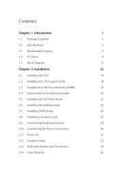
...1.2 Specifications 2 1.3 Motherboard Layout 6 1.4 I/O Panel 9 1.5 Block Diagram 12 Chapter 2 Installation 13 2.1 Installing the CPU 14 2.2 Installing the CPU Liquid Cooler 18 2.3 Installation of Memory Modules (DIMM) 20 2.4 Connecting the Front Panel Header 22 2.5 Installing the I/O Panel Shield 23 2.6 Installing the Motherboard 24 2.7 Installing SATA Drives 25 2.8 Installing a Graphics Card 27 2.9 Connecting Peripheral Devices 29 2.10 Connecting the Power Connectors 30 2.11 Power On 31 2.12 Jumpers Setup 32 2.13 Onboard Headers and Connectors 34 2.14 Smart...
...1.2 Specifications 2 1.3 Motherboard Layout 6 1.4 I/O Panel 9 1.5 Block Diagram 12 Chapter 2 Installation 13 2.1 Installing the CPU 14 2.2 Installing the CPU Liquid Cooler 18 2.3 Installation of Memory Modules (DIMM) 20 2.4 Connecting the Front Panel Header 22 2.5 Installing the I/O Panel Shield 23 2.6 Installing the Motherboard 24 2.7 Installing SATA Drives 25 2.8 Installing a Graphics Card 27 2.9 Connecting Peripheral Devices 29 2.10 Connecting the Power Connectors 30 2.11 Power On 31 2.12 Jumpers Setup 32 2.13 Onboard Headers and Connectors 34 2.14 Smart...
User Manual
Page 5
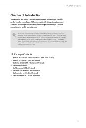
... Contents • ASRock WRX90 WS EVO Motherboard (EEB Form Factor) • ASRock WRX90 WS EVO User Manual • 4 x Serial ATA (SATA) Data Cables (Optional) • 1 x I/O Panel Shield • 2 x Thermistor Cables (Optional) • 1 x Multi PSU Adaptor Cable (Optional) • 2 x Screws for M.2 Sockets (Optional) • 2 x Standoffs for purchasing ASRock WRX90 WS EVO motherboard, a reliable motherboard produced under ASRock's consistently stringent quality control. You may find the latest VGA cards and CPU support list on ASRock's website without notice. In case any modifications...
... Contents • ASRock WRX90 WS EVO Motherboard (EEB Form Factor) • ASRock WRX90 WS EVO User Manual • 4 x Serial ATA (SATA) Data Cables (Optional) • 1 x I/O Panel Shield • 2 x Thermistor Cables (Optional) • 1 x Multi PSU Adaptor Cable (Optional) • 2 x Screws for M.2 Sockets (Optional) • 2 x Standoffs for purchasing ASRock WRX90 WS EVO motherboard, a reliable motherboard produced under ASRock's consistently stringent quality control. You may find the latest VGA cards and CPU support list on ASRock's website without notice. In case any modifications...
User Manual
Page 6
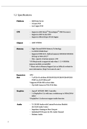
... PRO Processors • Supports AMD Socket sTR5 • Supports ASRock Hyper BCLK Engine Chipset • AMD WRX90 Memory • Eight Channel DDR5 Memory Technology • 8 x DDR5 DIMM Slots* • Supports DDR5 ECC, buffered memory (RDIMM/ RDIMM- 3DS) up to 1920x1200 @ 60Hz* * DisplayPort 1.1a does not support audio function. Audio • 7.1 CH HD Audio with max. resolution up to Memory Support List on Rear Out port • Individual PCB Layers for more information. (http://www.asrock.com/) Expansion Slot CPU...
... PRO Processors • Supports AMD Socket sTR5 • Supports ASRock Hyper BCLK Engine Chipset • AMD WRX90 Memory • Eight Channel DDR5 Memory Technology • 8 x DDR5 DIMM Slots* • Supports DDR5 ECC, buffered memory (RDIMM/ RDIMM- 3DS) up to 1920x1200 @ 60Hz* * DisplayPort 1.1a does not support audio function. Audio • 7.1 CH HD Audio with max. resolution up to Memory Support List on Rear Out port • Individual PCB Layers for more information. (http://www.asrock.com/) Expansion Slot CPU...
User Manual
Page 9
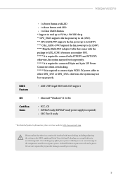
...: http://www.asrock.com Please realize that comes with overclocking, including adjusting the setting in the BIOS, applying Untied Overclocking Technology, or using third-party overclocking tools. Overclocking may not boot up properly. • AMI UEFI Legal BIOS with GUI support • Microsoft® Windows® 11 64-bit • FCC, CE • ErP/EuP ready (ErP/EuP ready power supply is required to connect 6 pin PCIE 12V power cables to either...
...: http://www.asrock.com Please realize that comes with overclocking, including adjusting the setting in the BIOS, applying Untied Overclocking Technology, or using third-party overclocking tools. Overclocking may not boot up properly. • AMI UEFI Legal BIOS with GUI support • Microsoft® Windows® 11 64-bit • FCC, CE • ErP/EuP ready (ErP/EuP ready power supply is required to connect 6 pin PCIE 12V power cables to either...
User Manual
Page 11
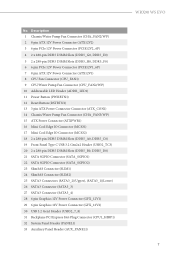
... Header (USB32_TC3) 20 2 x 288-pin DDR5 DIMM Slots (DDR5_B0, DDR5_D0) 21 SATA SGPIO Connector (SATA_SGPIO1) 22 SATA SGPIO Connector (SATA_SGPIO2) 23 SlimSAS Connector (SLIM1) 24 SlimSAS Connector (SLIM2) 25 SATA3 Connectors (SATA3_2)(Upper), (SATA3_1)(Lower) 26 SATA3 Connector (SATA3_3) 27 SATA3 Connector (SATA3_4) 28 6 pin Graphics 12V Power Connector (GFX_12V1) 29 6 pin Graphics 12V Power Connector (GFX_12V2) 30 USB 3.2 Gen1 Header (USB32_7_8) 31 Backplane PCI Express Hot-Plug Connector (CPU1_HSBP1) 32 System Panel Header (PANEL1) 33 Auxiliary Panel Header (AUX_PANEL1) WRX90 WS EVO...
... Header (USB32_TC3) 20 2 x 288-pin DDR5 DIMM Slots (DDR5_B0, DDR5_D0) 21 SATA SGPIO Connector (SATA_SGPIO1) 22 SATA SGPIO Connector (SATA_SGPIO2) 23 SlimSAS Connector (SLIM1) 24 SlimSAS Connector (SLIM2) 25 SATA3 Connectors (SATA3_2)(Upper), (SATA3_1)(Lower) 26 SATA3 Connector (SATA3_3) 27 SATA3 Connector (SATA3_4) 28 6 pin Graphics 12V Power Connector (GFX_12V1) 29 6 pin Graphics 12V Power Connector (GFX_12V2) 30 USB 3.2 Gen1 Header (USB32_7_8) 31 Backplane PCI Express Hot-Plug Connector (CPU1_HSBP1) 32 System Panel Header (PANEL1) 33 Auxiliary Panel Header (AUX_PANEL1) WRX90 WS EVO...
User Manual
Page 12
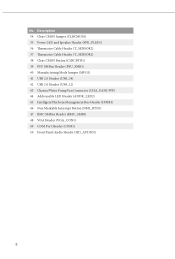
... Power LED and Speaker Header (SPK_PLED1) 36 Thermistor Cable Header (T_SENSOR2) 37 Thermistor Cable Header (T_SENSOR1) 38 Clear CMOS Button (CLRCBTN1) 39 PSU SMBus Header (PSU_SMB1) 40 Manufacturing Mode Jumper (MFG1) 41 USB 2.0 Header (USB_34) 42 USB 2.0 Header (USB_12) 43 Chassis/Water Pump Fan Connector (CHA_FAN1/WP) 44 Addressable LED Header (ADDR_LED2) 45 Intelligent Platform Management Bus Header (IPMB1) 46 Non Maskable Interrupt Button (NMI_BTN1) 47 BMC SMBus Header (BMC_SMB1) 48 VGA Header (VGA_CON1) 49 COM Port Header (COM1) 50 Front Panel Audio Header...
... Power LED and Speaker Header (SPK_PLED1) 36 Thermistor Cable Header (T_SENSOR2) 37 Thermistor Cable Header (T_SENSOR1) 38 Clear CMOS Button (CLRCBTN1) 39 PSU SMBus Header (PSU_SMB1) 40 Manufacturing Mode Jumper (MFG1) 41 USB 2.0 Header (USB_34) 42 USB 2.0 Header (USB_12) 43 Chassis/Water Pump Fan Connector (CHA_FAN1/WP) 44 Addressable LED Header (ADDR_LED2) 45 Intelligent Platform Management Bus Header (IPMB1) 46 Non Maskable Interrupt Button (NMI_BTN1) 47 BMC SMBus Header (BMC_SMB1) 48 VGA Header (VGA_CON1) 49 COM Port Header (COM1) 50 Front Panel Audio Header...
User Manual
Page 32
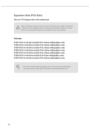
... connect a chassis fan to the motherboard's chassis fan connector (CHA_FAN1~3/WP) when using multiple graphics cards. 28 PCIE4 (PCIe 5.0 x16 slot) is used for PCIe x16 lane width graphics cards. Expansion Slots (PCIe Slots) There are 7 PCI Express slots on the motherboard. PCIE7 (PCIe 5.0 x16 slot) is used for PCIe x16 lane width graphics cards. Please read the documentation of the expansion card and make sure that the power supply is switched off or the power cord is used for PCIe x8 lane width graphics cards. PCIE2 (PCIe 5.0 x16 slot...
... connect a chassis fan to the motherboard's chassis fan connector (CHA_FAN1~3/WP) when using multiple graphics cards. 28 PCIE4 (PCIe 5.0 x16 slot) is used for PCIe x16 lane width graphics cards. Expansion Slots (PCIe Slots) There are 7 PCI Express slots on the motherboard. PCIE7 (PCIe 5.0 x16 slot) is used for PCIe x16 lane width graphics cards. Please read the documentation of the expansion card and make sure that the power supply is switched off or the power cord is used for PCIe x8 lane width graphics cards. PCIE2 (PCIe 5.0 x16 slot...
User Manual
Page 55
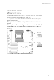
... motherboard provides two 8-pin ATX 12V power connectors. To use a 4-pin ATX power supply, please plug it along Pin 1 and Pin 5. * It is required to connect all 8 pin and 6 pin 12V Power Connectors when overclocking. *Warning: Please make sure that the power cable connected is required to connect both ATX12V1 and ATX12V2; otherwise, the system may not boot up properly. *It is for the CPU and not the graphics card. ATX12V1 8 5 4 1 ATX12V2 8 5 4 1 51 Do not plug the PCIe 6-pin power cable to...
... motherboard provides two 8-pin ATX 12V power connectors. To use a 4-pin ATX power supply, please plug it along Pin 1 and Pin 5. * It is required to connect all 8 pin and 6 pin 12V Power Connectors when overclocking. *Warning: Please make sure that the power cable connected is required to connect both ATX12V1 and ATX12V2; otherwise, the system may not boot up properly. *It is for the CPU and not the graphics card. ATX12V1 8 5 4 1 ATX12V2 8 5 4 1 51 Do not plug the PCIe 6-pin power cable to...
User Manual
Page 78
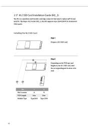
B A No. Nut Location PCB Length Module Type 1 A 6cm Type2260 2 B 8cm Type 2280 74 Installing the M.2 SSD Card Step 1 Prepare a M.2 SSD card. The Hyper M.2 Socket (M2_2, Key M) supports type 2260/2280 PCIe Gen4x4 (64 Gb/s) mode. Step 2 2 1 Depending on the PCB type and length of your M.2 SSD card, find the corresponding nut location to replace mPCIe and mSATA. 2.17 M.2 SSD Card Installation Guide (M2_2) The M.2 is a small size and versatile card edge connector that aims to be used.
B A No. Nut Location PCB Length Module Type 1 A 6cm Type2260 2 B 8cm Type 2280 74 Installing the M.2 SSD Card Step 1 Prepare a M.2 SSD card. The Hyper M.2 Socket (M2_2, Key M) supports type 2260/2280 PCIe Gen4x4 (64 Gb/s) mode. Step 2 2 1 Depending on the PCB type and length of your M.2 SSD card, find the corresponding nut location to replace mPCIe and mSATA. 2.17 M.2 SSD Card Installation Guide (M2_2) The M.2 is a small size and versatile card edge connector that aims to be used.
Software/BIOS Setup Guide
Page 3
...2.1 Auto Driver Installer (ADI) 2 2.1.1 Installing Drivers for the First Time 2 2.1.2 Updating Drivers 6 2.2 ASRock Live Update & APP Shop 7 2.2.1 Installing ASRock Live Update & APP Shop 7 2.2.2 UI Overview 8 2.2.3 Apps 9 2.2.4 BIOS & Drivers 12 2.2.5 Setting 13 2.3 ASRock Polychrome SYNC 14 2.3.1 Connecting the Addressable RGB LED Strip 14 2.3.2 Installing ASRock Polychrome SYNC Utility 15 2.4 Nahimic Audio 16 Chapter 3 UEFI SETUP UTILITY 18 3.1 Introduction 18 3.1.1 Entering BIOS Setup 18 3.1.2 UEFI Menu Bar 19 3.1.3 Navigation Keys 20 3.2 Main Screen 21...
...2.1 Auto Driver Installer (ADI) 2 2.1.1 Installing Drivers for the First Time 2 2.1.2 Updating Drivers 6 2.2 ASRock Live Update & APP Shop 7 2.2.1 Installing ASRock Live Update & APP Shop 7 2.2.2 UI Overview 8 2.2.3 Apps 9 2.2.4 BIOS & Drivers 12 2.2.5 Setting 13 2.3 ASRock Polychrome SYNC 14 2.3.1 Connecting the Addressable RGB LED Strip 14 2.3.2 Installing ASRock Polychrome SYNC Utility 15 2.4 Nahimic Audio 16 Chapter 3 UEFI SETUP UTILITY 18 3.1 Introduction 18 3.1.1 Entering BIOS Setup 18 3.1.2 UEFI Menu Bar 19 3.1.3 Navigation Keys 20 3.2 Main Screen 21...
Software/BIOS Setup Guide
Page 5
...Software Setup Guide • Auto Driver Installer (ADI) • ASRock Live Update & APP Shop • Nahimic Audio BIOS Setup Guide • UEFI Setup Utility Because the motherboard specifications and the software might be updated, the content of this documentation will be subject to change without further notice. ASRock website http:// www.asrock.com. 1 Chapter 3 contains the configuration guide of the software and utilities. In case any modifications of the setup guide. In this manual are using. AMD WRX90 Series Chapter 1 Introduction This user guide is a complete setup guide...
...Software Setup Guide • Auto Driver Installer (ADI) • ASRock Live Update & APP Shop • Nahimic Audio BIOS Setup Guide • UEFI Setup Utility Because the motherboard specifications and the software might be updated, the content of this documentation will be subject to change without further notice. ASRock website http:// www.asrock.com. 1 Chapter 3 contains the configuration guide of the software and utilities. In case any modifications of the setup guide. In this manual are using. AMD WRX90 Series Chapter 1 Introduction This user guide is a complete setup guide...
Software/BIOS Setup Guide
Page 6
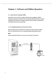
...instructions to install all necessary drivers automatically. 2.1.1 Installing Drivers for driver installation. Step 1 After you finish installing the operation system, simply use the Auto Driver Installer to the Internet. RJ-45 Cable LAN Port Modem Internet 2 Chapter 2 Software and Utilities Operation 2.1 Auto Driver Installer (ADI) Optical drive or driver DVD is required during the following procedures. ASRock motherboard already has its Ethernet driver prepacked in BIOS ROM. When you install the Windows OS, connect your computer to download and install all necessary drivers...
...instructions to install all necessary drivers automatically. 2.1.1 Installing Drivers for driver installation. Step 1 After you finish installing the operation system, simply use the Auto Driver Installer to the Internet. RJ-45 Cable LAN Port Modem Internet 2 Chapter 2 Software and Utilities Operation 2.1 Auto Driver Installer (ADI) Optical drive or driver DVD is required during the following procedures. ASRock motherboard already has its Ethernet driver prepacked in BIOS ROM. When you install the Windows OS, connect your computer to download and install all necessary drivers...
Software/BIOS Setup Guide
Page 7
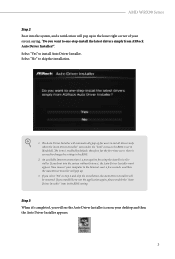
... corner of your screen saying, "Do you want to one-step-install the latest drivers simply from ASRock Auto Driver Installer?". Select "No" to the Internet, wait a few seconds, and then the Auto Driver Installer will pop up for users to install drivers only when the "Auto Driver Installer" item under the "Tool" menu in the BIOS. 2. therefore, for the first-time users, there is enabled by default; AMD WRX90 Series Step 2 Boot into the...
... corner of your screen saying, "Do you want to one-step-install the latest drivers simply from ASRock Auto Driver Installer?". Select "No" to the Internet, wait a few seconds, and then the Auto Driver Installer will pop up for users to install drivers only when the "Auto Driver Installer" item under the "Tool" menu in the BIOS. 2. therefore, for the first-time users, there is enabled by default; AMD WRX90 Series Step 2 Boot into the...
Software/BIOS Setup Guide
Page 9
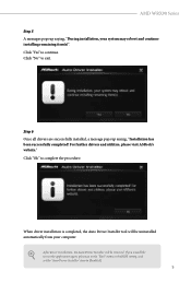
... be removed. Step 6 Once all drivers are successfully installed, a message pops up saying, "During installation, your computer. For further drivers and utilities, please visit ASRock's website." Click "Ok" to exit. Click "No" to complete the procedure. When driver installation is completed, the Auto Driver Installer tool will be uninstalled automatically from your system may reboot and continue installing remaining item(s)". Click "Yes" to [Enabled]. 5 AMD WRX90 Series...
... be removed. Step 6 Once all drivers are successfully installed, a message pops up saying, "During installation, your computer. For further drivers and utilities, please visit ASRock's website." Click "Ok" to exit. Click "No" to complete the procedure. When driver installation is completed, the Auto Driver Installer tool will be uninstalled automatically from your system may reboot and continue installing remaining item(s)". Click "Yes" to [Enabled]. 5 AMD WRX90 Series...
Software/BIOS Setup Guide
Page 10
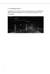
To update drivers, please go to ASRock' website (https://www.asrock.com) and select "Support" > "Latest Drivers Update". 6 2.1.2 Updating Drivers Updating drivers ensures that your system work well without any issue.
To update drivers, please go to ASRock' website (https://www.asrock.com) and select "Support" > "Latest Drivers Update". 6 2.1.2 Updating Drivers Updating drivers ensures that your system work well without any issue.
Software/BIOS Setup Guide
Page 22
... BIOS version of a trained service person. The battery on . You may run the UEFI SETUP UTILITY by pressing or right after you purchased for detailed screens, settings and options. 18 Chapter 3 UEFI SETUP UTILITY 3.1 Introduction ASRock UEFI (Unified Extensible Firmware Interface) is turned off and then back on the system chassis. If you do not alter the UEFI default configurations or change the setting, try to clear the CMOS values and reset the board to enter the UEFI SETUP UTILITY after POST...
... BIOS version of a trained service person. The battery on . You may run the UEFI SETUP UTILITY by pressing or right after you purchased for detailed screens, settings and options. 18 Chapter 3 UEFI SETUP UTILITY 3.1 Introduction ASRock UEFI (Unified Extensible Firmware Interface) is turned off and then back on the system chassis. If you do not alter the UEFI default configurations or change the setting, try to clear the CMOS values and reset the board to enter the UEFI SETUP UTILITY after POST...
Software/BIOS Setup Guide
Page 27
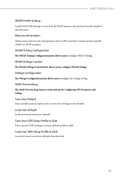
... to configure the voltage setting. Voltage Configuration The Voltage Configuration menu allows you to Disk Loads previously saved user defaults from the disk. 23 DRAM Voltage Control The DRAM Voltage Control menu allows you to configure DRAM Timing. AMD Overclocking The AMD Overclocking menu accesses options for DDR5 modules. Load User UEFI Setup Profile to configure DRAM Voltage. Memory Information Allows users to overclock the DDR5 memory and perform beyond standard specifications. AMD WRX90 Series DRAM Profile Setting Load EXPO/XMP settings to browse the serial presence...
... to configure the voltage setting. Voltage Configuration The Voltage Configuration menu allows you to Disk Loads previously saved user defaults from the disk. 23 DRAM Voltage Control The DRAM Voltage Control menu allows you to configure DRAM Timing. AMD Overclocking The AMD Overclocking menu accesses options for DDR5 modules. Load User UEFI Setup Profile to configure DRAM Voltage. Memory Information Allows users to overclock the DDR5 memory and perform beyond standard specifications. AMD WRX90 Series DRAM Profile Setting Load EXPO/XMP settings to browse the serial presence...
Software/BIOS Setup Guide
Page 41
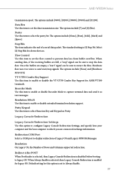
AMD WRX90 Series transmission speed. The options include [7] and [8] (Bits). Stop Bits The item indicates the end of Legacy OS and Legacy OPROM Messages. Select [2] Stop Bits for legacy OS. Hardware flow uses two wires to send start " signal can be sent to Always Enable. 37 VT-UTF8 Combo Key Support Use this item to which you are connected exchange information. Legacy Console Redirection Legacy Console Redirection Settings Use this item to enable or disable extended...
AMD WRX90 Series transmission speed. The options include [7] and [8] (Bits). Stop Bits The item indicates the end of Legacy OS and Legacy OPROM Messages. Select [2] Stop Bits for legacy OS. Hardware flow uses two wires to send start " signal can be sent to Always Enable. 37 VT-UTF8 Combo Key Support Use this item to which you are connected exchange information. Legacy Console Redirection Legacy Console Redirection Settings Use this item to enable or disable extended...
Software/BIOS Setup Guide
Page 42
... sent to select the serial port transmission speed. Option VT100 VT100+ VT-UTF8 ANSI Description ASCII character set Extended VT100 that supports color and function keys UTF8 encoding is set to Enabled, you are connected exchange information. Hardware flow uses two wires to send start " signal can select a COM Port to select [VT-UTF8]. Out-of-Band Mgmt Port Microsof t Windows Emergency Management Services (EMS) allows for...
... sent to select the serial port transmission speed. Option VT100 VT100+ VT-UTF8 ANSI Description ASCII character set Extended VT100 that supports color and function keys UTF8 encoding is set to Enabled, you are connected exchange information. Hardware flow uses two wires to send start " signal can select a COM Port to select [VT-UTF8]. Out-of-Band Mgmt Port Microsof t Windows Emergency Management Services (EMS) allows for...
RAID Installation Guide
Page 13
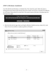
While the system is booting, please press [F11] to boot from. It should list the USB drive as a UEFI device. If the system restarts at this point. 13 Do not try to delete or create any partition at this picture. When the disk selection page shows up during the Windows installation process, please click . STEP 3: Windows installation Insert the USB drive with Windows 11 installation files. Please select this to open the boot menu that is shown in this point, then please open the [F11] boot menu again. 1. Then restart the system.
While the system is booting, please press [F11] to boot from. It should list the USB drive as a UEFI device. If the system restarts at this point. 13 Do not try to delete or create any partition at this picture. When the disk selection page shows up during the Windows installation process, please click . STEP 3: Windows installation Insert the USB drive with Windows 11 installation files. Please select this to open the boot menu that is shown in this point, then please open the [F11] boot menu again. 1. Then restart the system.


