
User Manual
Page 3
... Package Contents 1 1.2 Specifications 2 1.3 Motherboard Layout 5 1.4 I/O Panel 7 Chapter 2 Installation 9 2.1 Installing Memory Modules (SO-DIMM) 10 2.2 Expansion Slots (PCI Express Slots) 12 2.3 Jumpers Setup 13 2.4 Onboard Headers and Connectors 14 Chapter 3 Software and Utilities Operation 18 3.1 Installing Drivers 18 3.2 A-Tuning 19 3.3 Intel® Smart Connect Technology 21 3.4 ASRock Cloud 26 3.5 Start8 36 Chapter 4 UEFI SETUP UTILITY 39 4.1 Introduction 39 4.1.1 UEFI Menu Bar 39 4.1.2 Navigation Keys 40 4.2 Main Screen 41 4.3 Advanced Screen 42
... Package Contents 1 1.2 Specifications 2 1.3 Motherboard Layout 5 1.4 I/O Panel 7 Chapter 2 Installation 9 2.1 Installing Memory Modules (SO-DIMM) 10 2.2 Expansion Slots (PCI Express Slots) 12 2.3 Jumpers Setup 13 2.4 Onboard Headers and Connectors 14 Chapter 3 Software and Utilities Operation 18 3.1 Installing Drivers 18 3.2 A-Tuning 19 3.3 Intel® Smart Connect Technology 21 3.4 ASRock Cloud 26 3.5 Start8 36 Chapter 4 UEFI SETUP UTILITY 39 4.1 Introduction 39 4.1.1 UEFI Menu Bar 39 4.1.2 Navigation Keys 40 4.2 Main Screen 41 4.3 Advanced Screen 42
User Manual
Page 5
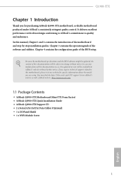
... to change without further notice. ASRock website http://www.asrock.com. 1.1 Package Contents • ASRock Q1900-ITX Motherboard (Mini-ITX Form Factor) • ASRock Q1900-ITX Quick Installation Guide • ASRock Q1900-ITX Support CD • 2 x Serial ATA (SATA) Data Cables (Optional) • 1 x I/O Panel Shield • 1 x WiFi Module Screw 1 English You may find the latest VGA cards and CPU support list on ASRock's website without notice. Q1900-ITX Chapter 1 Introduction Thank you are using. Because the motherboard specifications and the BIOS software might be updated, the...
... to change without further notice. ASRock website http://www.asrock.com. 1.1 Package Contents • ASRock Q1900-ITX Motherboard (Mini-ITX Form Factor) • ASRock Q1900-ITX Quick Installation Guide • ASRock Q1900-ITX Support CD • 2 x Serial ATA (SATA) Data Cables (Optional) • 1 x I/O Panel Shield • 1 x WiFi Module Screw 1 English You may find the latest VGA cards and CPU support list on ASRock's website without notice. Q1900-ITX Chapter 1 Introduction Thank you are using. Because the motherboard specifications and the BIOS software might be updated, the...

User Manual
Page 6
... CAUTION) Expansion Slot • 1 x PCI Express 2.0 x1 Slot • 1 x mini-PCI Express Slot Graphics • Intel® 7th generation (Gen 7) graphics • DirectX 11.0, Pixel Shader 5.0 • Three graphics output options: D-Sub, DVI-D and HDMI • Supports HDMI Technology with max. 1.2 Specifications Platform • Mini-ITX Form Factor • All Solid Capacitor design • High Density Glass Fabric PCB CPU • Intel® Quad-Core Processor J1900 (2 GHz) Memory • Dual Channel DDR3/DDR3L Memory Technology •...
... CAUTION) Expansion Slot • 1 x PCI Express 2.0 x1 Slot • 1 x mini-PCI Express Slot Graphics • Intel® 7th generation (Gen 7) graphics • DirectX 11.0, Pixel Shader 5.0 • Three graphics output options: D-Sub, DVI-D and HDMI • Supports HDMI Technology with max. 1.2 Specifications Platform • Mini-ITX Form Factor • All Solid Capacitor design • High Density Glass Fabric PCB CPU • Intel® Quad-Core Processor J1900 (2 GHz) Memory • Dual Channel DDR3/DDR3L Memory Technology •...
User Manual
Page 7
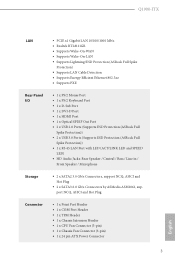
... (ASRock Full Spike Protection)) • 1 x RJ-45 LAN Port with LED (ACT/LINK LED and SPEED LED) • HD Audio Jacks: Rear Speaker / Central / Bass / Line in / Front Speaker / Microphone Storage • 2 x SATA2 3.0 Gb/s Connectors, support NCQ, AHCI and Hot Plug • 2 x SATA3 6.0 Gb/s Connectors by ASMedia ASM1061, support NCQ, AHCI and Hot Plug Connector • 1 x Print Port Header • 1 x COM Port Header • 1 x TPM Header • 1 x Chassis Intrusion Header • 1 x CPU Fan Connector (3-pin) • 1 x Chassis Fan Connector (3-pin) • 1 x 24 pin ATX Power...
... (ASRock Full Spike Protection)) • 1 x RJ-45 LAN Port with LED (ACT/LINK LED and SPEED LED) • HD Audio Jacks: Rear Speaker / Central / Bass / Line in / Front Speaker / Microphone Storage • 2 x SATA2 3.0 Gb/s Connectors, support NCQ, AHCI and Hot Plug • 2 x SATA3 6.0 Gb/s Connectors by ASMedia ASM1061, support NCQ, AHCI and Hot Plug Connector • 1 x Print Port Header • 1 x COM Port Header • 1 x TPM Header • 1 x Chassis Intrusion Header • 1 x CPU Fan Connector (3-pin) • 1 x Chassis Fan Connector (3-pin) • 1 x 24 pin ATX Power...

User Manual
Page 8
... 2 USB 3.0 ports) (Supports ESD Protection (ASRock Full Spike Protection)) • 64Mb AMI UEFI Legal BIOS with GUI support • Supports Plug and Play • ACPI 1.1 compliant wake up events • Supports jumperfree • SMBIOS 2.3.1 support • CPU/Chassis temperature sensing • CPU/Chassis Fan Tachometer • CPU/Chassis Quiet Fan (Auto adjust chassis fan speed by CPU temperature) • CPU/Chassis Fan multi-speed control • CASE OPEN detection • Voltage monitoring: +12V, +5V, +3.3V, CPU Vcore • Microsoft® Windows® 8.1 32-bit / 8.1 64-bit...
... 2 USB 3.0 ports) (Supports ESD Protection (ASRock Full Spike Protection)) • 64Mb AMI UEFI Legal BIOS with GUI support • Supports Plug and Play • ACPI 1.1 compliant wake up events • Supports jumperfree • SMBIOS 2.3.1 support • CPU/Chassis temperature sensing • CPU/Chassis Fan Tachometer • CPU/Chassis Quiet Fan (Auto adjust chassis fan speed by CPU temperature) • CPU/Chassis Fan multi-speed control • CASE OPEN detection • Voltage monitoring: +12V, +5V, +3.3V, CPU Vcore • Microsoft® Windows® 8.1 32-bit / 8.1 64-bit...

User Manual
Page 9
1.3 Motherboard Layout 64Mb BIOS CPU_FAN1 DDR3_A1 Q1900-ITX PS2 Mouse PS2 Keyboard RoHS Q1900-ITX DVI1 VGA1 AT X P W R 1 DDR3_B1 Front USB 3.0 USB 2.0 T: USB3 B: USB4 CMOS Battery MINI_PCIE1 USB 3.0 T: USB3 Top: RJ-45 LAN B: USB4 HD_AUDIO1 1 Super I/O Top: CTR BASS Center: REAR SPK FRONT Top: LINE IN Center: AUDIO CODEC LPT1 1 PCIE1 USB1_2 1 SATA3_A2 SATA3_A1 SATA2_2 SATA2_1 COM1 1 TPMS1 1 CLRCMOS1 CI1 1 1 SPEAKER1 1 USB3_1_2 PANEL1 PLED PWRBTN 1 HDLED RESET Bottom: MIC IN HDMI Bottom: Optical SPDIF English 5
1.3 Motherboard Layout 64Mb BIOS CPU_FAN1 DDR3_A1 Q1900-ITX PS2 Mouse PS2 Keyboard RoHS Q1900-ITX DVI1 VGA1 AT X P W R 1 DDR3_B1 Front USB 3.0 USB 2.0 T: USB3 B: USB4 CMOS Battery MINI_PCIE1 USB 3.0 T: USB3 Top: RJ-45 LAN B: USB4 HD_AUDIO1 1 Super I/O Top: CTR BASS Center: REAR SPK FRONT Top: LINE IN Center: AUDIO CODEC LPT1 1 PCIE1 USB1_2 1 SATA3_A2 SATA3_A1 SATA2_2 SATA2_1 COM1 1 TPMS1 1 CLRCMOS1 CI1 1 1 SPEAKER1 1 USB3_1_2 PANEL1 PLED PWRBTN 1 HDLED RESET Bottom: MIC IN HDMI Bottom: Optical SPDIF English 5

User Manual
Page 13
Failure to do so may damage the motherboard. 9 English Q1900-ITX Chapter 2 Installation This is a Mini-ITX form factor motherboard. Before you install the motherboard, study the configuration of the following precautions before installing or removing the motherboard. Also remember to use a grounded wrist strap or touch a safety grounded object before you handle the components. • Hold components by the edges and do not overtighten...
Failure to do so may damage the motherboard. 9 English Q1900-ITX Chapter 2 Installation This is a Mini-ITX form factor motherboard. Before you install the motherboard, study the configuration of the following precautions before installing or removing the motherboard. Also remember to use a grounded wrist strap or touch a safety grounded object before you handle the components. • Hold components by the edges and do not overtighten...

User Manual
Page 17
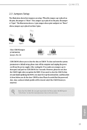
... pins, the jumper is "Open". If no jumper cap is placed on CLRCMOS1 for 15 seconds, use a jumper cap to default setup, please turn off the computer and unplug the power cord from the power supply. If you clear the CMOS, the case open may be cleared only if the CMOS battery is "Short". Clear CMOS Jumper (CLRCMOS1) (see p.5, No. 13) Default Clear CMOS CLRCMOS1 allows you to clear the CMOS when you just finish updating the BIOS...
... pins, the jumper is "Open". If no jumper cap is placed on CLRCMOS1 for 15 seconds, use a jumper cap to default setup, please turn off the computer and unplug the power cord from the power supply. If you clear the CMOS, the case open may be cleared only if the CMOS battery is "Short". Clear CMOS Jumper (CLRCMOS1) (see p.5, No. 13) Default Clear CMOS CLRCMOS1 allows you to clear the CMOS when you just finish updating the BIOS...

User Manual
Page 20
...) to this header. Chassis Speaker Header (4-pin SPEAKER1) (see p.5, No. 11) Chassis Fan Connector (3-pin CHA_FAN1) (see p.5, No. 8) FAN_SPEED FAN_VOLTAGE GND CPU Fan Connectors (3-pin CPU_FAN1) (see p.5, No. 1) GND FAN_VOLTAGE FAN_SPEED ATX Power Connector (24-pin ATXPWR1) (see p.5, No. 3) 12 24 1 13 Please connect the chassis speaker to Ground (GND). To use an AC'97 audio panel, please install it along Pin 1 and Pin 13. English 16 If you use a 20-pin ATX power supply, please plug it to install your system. 2. MIC_RET...
...) to this header. Chassis Speaker Header (4-pin SPEAKER1) (see p.5, No. 11) Chassis Fan Connector (3-pin CHA_FAN1) (see p.5, No. 8) FAN_SPEED FAN_VOLTAGE GND CPU Fan Connectors (3-pin CPU_FAN1) (see p.5, No. 1) GND FAN_VOLTAGE FAN_SPEED ATX Power Connector (24-pin ATXPWR1) (see p.5, No. 3) 12 24 1 13 Please connect the chassis speaker to Ground (GND). To use an AC'97 audio panel, please install it along Pin 1 and Pin 13. English 16 If you use a 20-pin ATX power supply, please plug it to install your system. 2. MIC_RET...
User Manual
Page 22
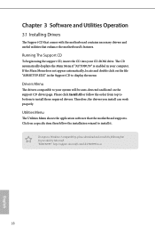
.... Drivers Menu The drivers compatible to your system will be auto-detected and listed on the file "ASRSETUP.EXE" in your CD-ROM drive. Please click Install All or follow the installation wizard to install those required drivers. Utilities Menu The Utilities Menu shows the application software that enhance the motherboard's features. Chapter 3 Software and Utilities Operation 3.1 Installing Drivers The Support CD that comes with the motherboard contains necessary drivers and useful utilities that the motherboard supports. Click on a specific item...
.... Drivers Menu The drivers compatible to your system will be auto-detected and listed on the file "ASRSETUP.EXE" in your CD-ROM drive. Please click Install All or follow the installation wizard to install those required drivers. Utilities Menu The Utilities Menu shows the application software that enhance the motherboard's features. Chapter 3 Software and Utilities Operation 3.1 Installing Drivers The Support CD that comes with the motherboard contains necessary drivers and useful utilities that the motherboard supports. Click on a specific item...
User Manual
Page 25
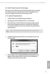
...\services\ msahci in AHCI mode, please follow the instructions below. If your motherboard supports this feature. • Operating system: Microsoft Windows 8/7 (32- Please backup any important data before operating to crash while booting. Double click on OK. 21 English or 64-bit edition) • Set the SATA mode to refresh email or social networking applications. Q1900-ITX 3.3 Intel® Smart Connect Technology Intel® Smart Connect Technology is a feature that periodically wakes...
...\services\ msahci in AHCI mode, please follow the instructions below. If your motherboard supports this feature. • Operating system: Microsoft Windows 8/7 (32- Please backup any important data before operating to crash while booting. Double click on OK. 21 English or 64-bit edition) • Set the SATA mode to refresh email or social networking applications. Q1900-ITX 3.3 Intel® Smart Connect Technology Intel® Smart Connect Technology is a feature that periodically wakes...
User Manual
Page 36
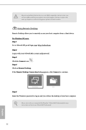
... Remote Desktop. For Windows PC users: Step 1 Go to remotely access your host computer from a client device. If the Remote Desktop Connection dialog appears, click Connect to online. Please refer to log in order to bring power option icon back to continue. Step 3 Click the Connect icon . Step 5 Enter the Windows password to the user manual of your Orbweb.ME account and password. You have to physically wake...
... Remote Desktop. For Windows PC users: Step 1 Go to remotely access your host computer from a client device. If the Remote Desktop Connection dialog appears, click Connect to online. Please refer to log in order to bring power option icon back to continue. Step 3 Click the Connect icon . Step 5 Enter the Windows password to the user manual of your Orbweb.ME account and password. You have to physically wake...

User Manual
Page 50
... down. Deep S5 Configure deep sleep mode for PCIE1. It will start to boot up when the power recovers. PCIE1 Link Speed Select the link speed for power saving when the computer is selected, the power will remain off the Power and LAN LEDs when the system enters into Standby/Hibernation mode. 46 English Good Night LED By enabling Good Night LED, the Power/LAN LEDs will be switched off when the...
... down. Deep S5 Configure deep sleep mode for PCIE1. It will start to boot up when the power recovers. PCIE1 Link Speed Select the link speed for power saving when the computer is selected, the power will remain off the Power and LAN LEDs when the system enters into Standby/Hibernation mode. 46 English Good Night LED By enabling Good Night LED, the Power/LAN LEDs will be switched off when the...

User Manual
Page 57
Legacy USB Support Enable or disable Legacy OS Support for USB 2.0 devices. Select UEFI Setup Only to disable legacy USB support. If you encounter USB compatibility issues it is recommended to support USB devices under the UEFI setup and Windows/Linux operating systems only. 53 English USB 3.0 Controller Enable or disable all the USB ports. 4.3.7 USB Configuration Q1900-ITX USB Controller Enable or disable all the USB 3.0 ports.
Legacy USB Support Enable or disable Legacy OS Support for USB 2.0 devices. Select UEFI Setup Only to disable legacy USB support. If you encounter USB compatibility issues it is recommended to support USB devices under the UEFI setup and Windows/Linux operating systems only. 53 English USB 3.0 Controller Enable or disable all the USB ports. 4.3.7 USB Configuration Q1900-ITX USB Controller Enable or disable all the USB 3.0 ports.
User Manual
Page 59
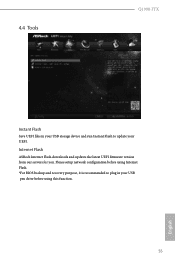
Internet Flash ASRock Internet Flash downloads and updates the latest UEFI firmware version from our servers for you. 4.4 Tools Q1900-ITX Instant Flash Save UEFI files in your UEFI. Please setup network configuration before using Internet Flash. *For BIOS backup and recovery purpose, it is recommended to plug in your USB storage device and run Instant Flash to update your USB pen drive before using this function. 55 English
Internet Flash ASRock Internet Flash downloads and updates the latest UEFI firmware version from our servers for you. 4.4 Tools Q1900-ITX Instant Flash Save UEFI files in your UEFI. Please setup network configuration before using Internet Flash. *For BIOS backup and recovery purpose, it is recommended to plug in your USB storage device and run Instant Flash to update your USB pen drive before using this function. 55 English

User Manual
Page 60
UEFI Download Server Select a server to configure internet connection settings for Internet Flash. Network Configuration Use this to download the UEFI firmware. 56 English Internet Setting Enable or disable sound effects in the setup utility.
UEFI Download Server Select a server to configure internet connection settings for Internet Flash. Network Configuration Use this to download the UEFI firmware. 56 English Internet Setting Enable or disable sound effects in the setup utility.

Quick Installation Guide
Page 8
...) playback with DVI-D and HDMI Ports Audio • 7.1 CH HD Audio with max. resolution up to 1920x1200 @ 60Hz • Supports DVI-D with max. 1.2 Specifications Platform • Mini-ITX Form Factor • All Solid Capacitor design • High Density Glass Fabric PCB CPU • Intel® Quad-Core Processor J1900 (2 GHz) Memory • Dual Channel DDR3/DDR3L Memory Technology • 2 x DDR3/DDR3L SO-DIMM Slots • Supports DDR3/DDR3L 1333/1066...
...) playback with DVI-D and HDMI Ports Audio • 7.1 CH HD Audio with max. resolution up to 1920x1200 @ 60Hz • Supports DVI-D with max. 1.2 Specifications Platform • Mini-ITX Form Factor • All Solid Capacitor design • High Density Glass Fabric PCB CPU • Intel® Quad-Core Processor J1900 (2 GHz) Memory • Dual Channel DDR3/DDR3L Memory Technology • 2 x DDR3/DDR3L SO-DIMM Slots • Supports DDR3/DDR3L 1333/1066...

Quick Installation Guide
Page 10
... 2 USB 3.0 ports) (Supports ESD Protection (ASRock Full Spike Protection)) • 64Mb AMI UEFI Legal BIOS with GUI support • Supports Plug and Play • ACPI 1.1 compliant wake up events • Supports jumperfree • SMBIOS 2.3.1 support • CPU/Chassis temperature sensing • CPU/Chassis Fan Tachometer • CPU/Chassis Quiet Fan (Auto adjust chassis fan speed by CPU temperature) • CPU/Chassis Fan multi-speed control • CASE OPEN detection • Voltage monitoring: +12V, +5V, +3.3V, CPU Vcore • Microsoft® Windows® 8.1 32-bit / 8.1 64-bit...
... 2 USB 3.0 ports) (Supports ESD Protection (ASRock Full Spike Protection)) • 64Mb AMI UEFI Legal BIOS with GUI support • Supports Plug and Play • ACPI 1.1 compliant wake up events • Supports jumperfree • SMBIOS 2.3.1 support • CPU/Chassis temperature sensing • CPU/Chassis Fan Tachometer • CPU/Chassis Quiet Fan (Auto adjust chassis fan speed by CPU temperature) • CPU/Chassis Fan multi-speed control • CASE OPEN detection • Voltage monitoring: +12V, +5V, +3.3V, CPU Vcore • Microsoft® Windows® 8.1 32-bit / 8.1 64-bit...
Quick Installation Guide
Page 15
..., use a jumper cap to default setup, please turn off the computer and unplug the power cord from the power supply. To clear and reset the system parameters to short pin2 and pin3 on the pins, the jumper is removed. If you update the BIOS. Please adjust the BIOS option "Clear Status" to clear the data in CMOS. However, please do the clear-CMOS action. Q1900-ITX 2.3 Jumpers Setup The illustration shows how jumpers are "Short" when a jumper cap is "Short". English...
..., use a jumper cap to default setup, please turn off the computer and unplug the power cord from the power supply. To clear and reset the system parameters to short pin2 and pin3 on the pins, the jumper is removed. If you update the BIOS. Please adjust the BIOS option "Clear Status" to clear the data in CMOS. However, please do the clear-CMOS action. Q1900-ITX 2.3 Jumpers Setup The illustration shows how jumpers are "Short" when a jumper cap is "Short". English...

Quick Installation Guide
Page 18
... motherboard provides a 24-pin ATX power connector. If you use a 20-pin ATX power supply, please plug it to OUT2_L. E. To use an AC'97 audio panel, please install it along Pin 1 and Pin 13. MIC_RET and OUT_RET are for the AC'97 audio panel. 1. High Definition Audio supports Jack Sensing, but the panel wire on the chassis must support HDA to MIC2_L. Connect Ground (GND) to the ground pin. B. Please connect the CPU fan cable to the connector and match the black wire...
... motherboard provides a 24-pin ATX power connector. If you use a 20-pin ATX power supply, please plug it to OUT2_L. E. To use an AC'97 audio panel, please install it along Pin 1 and Pin 13. MIC_RET and OUT_RET are for the AC'97 audio panel. 1. High Definition Audio supports Jack Sensing, but the panel wire on the chassis must support HDA to MIC2_L. Connect Ground (GND) to the ground pin. B. Please connect the CPU fan cable to the connector and match the black wire...


