User Manual
Page 3
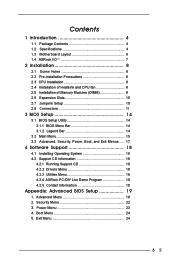
... Security Menu 22 3. Boot Menu 24 5. Contents 1 Introduction 4 1.1 Package Contents 4 1.2 Specifications 4 1.3 Motherboard Layout 6 1.4 ASRock I/OTM 7 2 Installation 8 2.1 Screw Holes 8 2.2 Pre-installation Precautions 8 2.3 CPU Installation 8 2.4 Installation of Heatsink and CPU fan 9 2.5 Installation of Memory Modules (DIMM 9 2.6 Expansion Slots 10 2.7 Jumpers Setup 10 2.8 Connectors 11 3 BIOS Setup 14 3.1 BIOS Setup Utility 14 3.1.1 BIOS Menu Bar 14 3.1.2 Legend Bar 14 3.2 Main Menu 15 3.3 Advanced, Security, Power, Boot, and Exit Menus ..... 17 4 Software Support...
... Security Menu 22 3. Boot Menu 24 5. Contents 1 Introduction 4 1.1 Package Contents 4 1.2 Specifications 4 1.3 Motherboard Layout 6 1.4 ASRock I/OTM 7 2 Installation 8 2.1 Screw Holes 8 2.2 Pre-installation Precautions 8 2.3 CPU Installation 8 2.4 Installation of Heatsink and CPU fan 9 2.5 Installation of Memory Modules (DIMM 9 2.6 Expansion Slots 10 2.7 Jumpers Setup 10 2.8 Connectors 11 3 BIOS Setup 14 3.1 BIOS Setup Utility 14 3.1.1 BIOS Menu Bar 14 3.1.2 Legend Bar 14 3.2 Main Menu 15 3.3 Advanced, Security, Power, Boot, and Exit Menus ..... 17 4 Software Support...
User Manual
Page 4
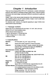
... to ASRock's commitment to 4 IDE devices Floppy Port: Supports floppy disk drive Audio: 5.1 channels AC'97 Audio LAN: Speed: 802.3u (10/100 Ethernet), supports Wake-On-LAN Hardware Monitor: CPU temperature sensing (ASRock U-COP); Chassis temperature sensing; Chassis fan tachometer 4 Chapter 1 and 2 of this manual contain introduction of the motherboard and step-bystep installation guide for purchasing ASRock PE Pro-HT motherboard, a reliable motherboard produced under ASRock's consistently stringent quality control. CPU overheat shutdown to protect CPU life (ASRock U-COP...
... to ASRock's commitment to 4 IDE devices Floppy Port: Supports floppy disk drive Audio: 5.1 channels AC'97 Audio LAN: Speed: 802.3u (10/100 Ethernet), supports Wake-On-LAN Hardware Monitor: CPU temperature sensing (ASRock U-COP); Chassis temperature sensing; Chassis fan tachometer 4 Chapter 1 and 2 of this manual contain introduction of the motherboard and step-bystep installation guide for purchasing ASRock PE Pro-HT motherboard, a reliable motherboard produced under ASRock's consistently stringent quality control. CPU overheat shutdown to protect CPU life (ASRock U-COP...
User Manual
Page 5
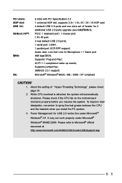
... Microsoft® Windows® XP. About the setting of header for USB 2.0 works fine under Microsoft® Windows® 98/ME/2000. While CPU overheat is detected, the system will automatically shutdown. PCI slots: AGP slot: USB 2.0: ASRock I/OTM: BIOS: OS: 6 slots with PCI Specification 2.2 1 universal AGP slot, supports 3.3v / 1.5v, 4X / 2X / 1X AGP card 4 default USB 2.0 ports and one extra set of "Hyper-Threading Technology", please check page 19. 2. Supports "Plug and Play"; To...
... Microsoft® Windows® XP. About the setting of header for USB 2.0 works fine under Microsoft® Windows® 98/ME/2000. While CPU overheat is detected, the system will automatically shutdown. PCI slots: AGP slot: USB 2.0: ASRock I/OTM: BIOS: OS: 6 slots with PCI Specification 2.2 1 universal AGP slot, supports 3.3v / 1.5v, 4X / 2X / 1X AGP card 4 default USB 2.0 ports and one extra set of "Hyper-Threading Technology", please check page 19. 2. Supports "Plug and Play"; To...
User Manual
Page 6
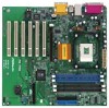
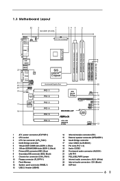
... 17 PE PRO-HT CLRCMOS1 CMOS Battery PCI 6 ATA133 USB2.0 5.1CH PANEL 1 PLED PWRBTN 1 HDLED RST 12 1 ATX power connector (ATXPWR1) 2 CPU socket 3 CPU fan connector (CPU_FAN1) 4 North Bridge controller 5 184-pin DDR DIMM slots (DDR1-2, Blue) 6 168-pin SDRAM DIMM slots (SDR1-2, Black) 7 Primary IDE connector (IDE1, Blue) 8 Secondary IDE connector (IDE2, Black) 9 Chassis fan connector (CHA_FAN1) 10 Floppy connector (FLOPPY1) 11 Flash Memory 12 System panel connector (PANEL1) 13 USB 2.0 header (USB45) 14 Infrared module connector (IR1) 15 External speaker connector...
... 17 PE PRO-HT CLRCMOS1 CMOS Battery PCI 6 ATA133 USB2.0 5.1CH PANEL 1 PLED PWRBTN 1 HDLED RST 12 1 ATX power connector (ATXPWR1) 2 CPU socket 3 CPU fan connector (CPU_FAN1) 4 North Bridge controller 5 184-pin DDR DIMM slots (DDR1-2, Blue) 6 168-pin SDRAM DIMM slots (SDR1-2, Black) 7 Primary IDE connector (IDE1, Blue) 8 Secondary IDE connector (IDE2, Black) 9 Chassis fan connector (CHA_FAN1) 10 Floppy connector (FLOPPY1) 11 Flash Memory 12 System panel connector (PANEL1) 13 USB 2.0 header (USB45) 14 Infrared module connector (IR1) 15 External speaker connector...
User Manual
Page 8
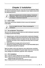
... damage the motherboard. 2.2 Pre-installation Precautions Take note of the socket lever. Carefully insert the CPU into it fits in the bag that its marked corner matches the base of the following precautions before installing or removing the motherboard. Chapter 2 Installation PE Pro-HT is detached from the wall socket before you uninstall any component. 2. Failure to ensure that the power is switched off or...
... damage the motherboard. 2.2 Pre-installation Precautions Take note of the socket lever. Carefully insert the CPU into it fits in the bag that its marked corner matches the base of the following precautions before installing or removing the motherboard. Chapter 2 Installation PE Pro-HT is detached from the wall socket before you uninstall any component. 2. Failure to ensure that the power is switched off or...
User Manual
Page 9
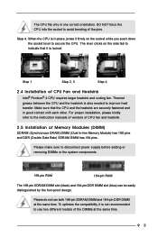
... power supply before adding or removing DIMMs or the system components. 168-pin RAM 184-pin RAM The 168-pin SDRAM DIMM slot (black) and 184-pin DDR DIMM slot (blue) can be easily distinguished by the fool-proof design. To optimize the compatibility, it is not recommended to the instruction manuals of vendors of CPU fan and heatsink. 2.5 Installation of CPU Fan and Heatsink Intel® Pentium® 4 CPU requires larger heatsink...
... power supply before adding or removing DIMMs or the system components. 168-pin RAM 184-pin RAM The 168-pin SDRAM DIMM slot (black) and 184-pin DDR DIMM slot (blue) can be easily distinguished by the fool-proof design. To optimize the compatibility, it is not recommended to the instruction manuals of vendors of CPU fan and heatsink. 2.5 Installation of CPU Fan and Heatsink Intel® Pentium® 4 CPU requires larger heatsink...
User Manual
Page 10
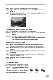
... retaining clips outward. The illustration shows a 3-pin jumper whose pin1 and pin2 are 6 PCI slots and 1 AGP slot on pins, the jumper is "OPEN". Step 2. Step 3. PCI slots: PCI slots are setup. Before installing the expansion card, read the documentation of the expansion card and make necessary hardware settings for later use . Keep the screw for the card. Align the card connector with screws. If no jumper cap is placed on PE Pro-HT motherboard.
... retaining clips outward. The illustration shows a 3-pin jumper whose pin1 and pin2 are 6 PCI slots and 1 AGP slot on pins, the jumper is "OPEN". Step 2. Step 3. PCI slots: PCI slots are setup. Before installing the expansion card, read the documentation of the expansion card and make necessary hardware settings for later use . Keep the screw for the card. Align the card connector with screws. If no jumper cap is placed on PE Pro-HT motherboard.
User Manual
Page 11
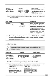
... the floppy ribbon cable with Pin1. Note: To select +5VSB, it requires 2 Amp and higher standby current provided by using metal material, e.g., a paper clip. DO NOT place jumper caps over these connectors. Clear CMOS CLRCMOS1 (see p.6 item 17) solder points Description To clear and reset the system parameters to default setup, please turn off the computer and unplug the power cord, then short the...
... the floppy ribbon cable with Pin1. Note: To select +5VSB, it requires 2 Amp and higher standby current provided by using metal material, e.g., a paper clip. DO NOT place jumper caps over these connectors. Clear CMOS CLRCMOS1 (see p.6 item 17) solder points Description To clear and reset the system parameters to default setup, please turn off the computer and unplug the power cord, then short the...
User Manual
Page 12
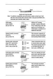
...) USB_PWR P-5 P+5 GND DUMMY 1 GND P+4 P-4 USB_PWR ASRock I/OTM already provided 4 default USB ports. Blue Connect to the motherboard Black Connect to the IDE devices 80-Pin ATA 100/133 cable Note: To optimize compatibility and performance, please connect your hard disk drive to the primary IDE connector (IDE1, blue) and CD-ROM to receive stereo audio input from sound sources such as a CD-ROM, DVD-ROM, TV tuner card, or MPEG card. USB header (9-pin USB45) (see p.6 item 23) CD...
...) USB_PWR P-5 P+5 GND DUMMY 1 GND P+4 P-4 USB_PWR ASRock I/OTM already provided 4 default USB ports. Blue Connect to the motherboard Black Connect to the IDE devices 80-Pin ATA 100/133 cable Note: To optimize compatibility and performance, please connect your hard disk drive to the primary IDE connector (IDE1, blue) and CD-ROM to receive stereo audio input from sound sources such as a CD-ROM, DVD-ROM, TV tuner card, or MPEG card. USB header (9-pin USB45) (see p.6 item 23) CD...
User Manual
Page 14
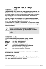
... your system using the BIOS Setup Utility. Because the BIOS software is constantly being updated, the following BIOS setup screens and descriptions are for you to locate and load the Operating System EXIT Exits the current menu or the BIOS Setup To access the menu bar items, press the right or left arrow key on the system chassis. You can also restart by pressing the reset button on the keyboard until the...
... your system using the BIOS Setup Utility. Because the BIOS software is constantly being updated, the following BIOS setup screens and descriptions are for you to locate and load the Operating System EXIT Exits the current menu or the BIOS Setup To access the menu bar items, press the right or left arrow key on the system chassis. You can also restart by pressing the reset button on the keyboard until the...

User Manual
Page 15
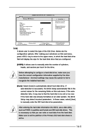
... a highlighted field Resets the current screen to its Setup Defaults Saves changes and exits Setup 3.2 Main Menu When you specify. Floppy Drives Use this to configure IDE devices. 15 Main Advanced System Date System Time Floppy Drives IDE Devices BIOS Version Processor Type Processor Speed Cache Size Microcode Update Total Memory DDR1 DDR2 SDR1 SDR2 AMIBIOS SETUP UTILITY - VERSION 3.31a Security Power Boot Exit Dec 25 2002 Wed 14:07:40 [ Setup Help ] Month: Jan - Navigation Key(s) / / + / Function Description Displays the General Help Screen Jumps to the...
... a highlighted field Resets the current screen to its Setup Defaults Saves changes and exits Setup 3.2 Main Menu When you specify. Floppy Drives Use this to configure IDE devices. 15 Main Advanced System Date System Time Floppy Drives IDE Devices BIOS Version Processor Type Processor Speed Cache Size Microcode Update Total Memory DDR1 DDR2 SDR1 SDR2 AMIBIOS SETUP UTILITY - VERSION 3.31a Security Power Boot Exit Dec 25 2002 Wed 14:07:40 [ Setup Help ] Month: Jan - Navigation Key(s) / / + / Function Description Displays the General Help Screen Jumps to the...
User Manual
Page 16
Main AMIBIOS SETUP UTILITY - Before attempting to configure a hard disk drive, make sure you configured. [USER]: It allows user to manually enter the number of the IDE Drive. This is successful, the BIOS Setup automatically fills in the correct values for the remaining fields on this sub-menu, press key to return to automatically detect hard disk drive. After entering the hard disk information into BIOS, use a disk utility, such as FDISK, to manually enter the IDE hard disk drive parameters. If auto-detection is necessary...
Main AMIBIOS SETUP UTILITY - Before attempting to configure a hard disk drive, make sure you configured. [USER]: It allows user to manually enter the number of the IDE Drive. This is successful, the BIOS Setup automatically fills in the correct values for the remaining fields on this sub-menu, press key to return to automatically detect hard disk drive. After entering the hard disk information into BIOS, use a disk utility, such as FDISK, to manually enter the IDE hard disk drive parameters. If auto-detection is necessary...
User Manual
Page 17
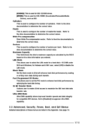
[CD/DVD]: This is used for IDE CD/DVD drives. [ARMD]: This is used to configure the number of these menus are listed in the Appendix. Refer to the drive documentation to determine the correct values. Block Mode Set the block mode to [On] will enhance hard disk performance by optimizing the hard disk timing. 32 Bit Transfer Mode It allows user to enable 32-bit access to maximize the IDE hard disk data transfer rate...
[CD/DVD]: This is used for IDE CD/DVD drives. [ARMD]: This is used to configure the number of these menus are listed in the Appendix. Refer to the drive documentation to determine the correct values. Block Mode Set the block mode to [On] will enhance hard disk performance by optimizing the hard disk timing. 32 Bit Transfer Mode It allows user to enable 32-bit access to maximize the IDE hard disk data transfer rate...
User Manual
Page 18
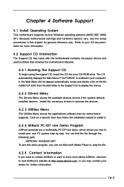
... the motherboard contains necessary drivers and useful utilities that the motherboard supports. Because motherboard settings and hardware options vary, use the setup procedures in this demo program, you can find the file through the following path: ..\ MPEGAV \ AVSEQ01.DAT To see this chapter for general reference only. Click on the file ASSETUP.EXE from the BIN folder in your CD-ROM drive. Refer to install it. 4.2.4 ASRock...
... the motherboard contains necessary drivers and useful utilities that the motherboard supports. Because motherboard settings and hardware options vary, use the setup procedures in this demo program, you can find the file through the following path: ..\ MPEGAV \ AVSEQ01.DAT To see this chapter for general reference only. Click on the file ASSETUP.EXE from the BIN folder in your CD-ROM drive. Refer to install it. 4.2.4 ASRock...
User Manual
Page 19
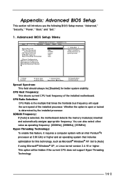
... technology, such as operating frequency: [200MHz], [266MHz], [333MHz]. CPU Ratio Selection: CPU Ratio is the multiple that includes optimization for better system stability. Appendix: Advanced BIOS Setup This section will equal the core speed of the installed processor. Advanced BIOS Setup Menu Main Advanced AMIBIOS SETUP UTILITY - VERSION 3.31a Security Power Boot Exit Spread Spectrum CPU Host Frequency Actual Frequency CPU Ratio Selection SDRAM Frequency Hyper Threading Technology Disabled Auto 133MHz Locked Auto Auto [ Setup Help ] to [Auto] if using Microsoft® Windows...
... technology, such as operating frequency: [200MHz], [266MHz], [333MHz]. CPU Ratio Selection: CPU Ratio is the multiple that includes optimization for better system stability. Appendix: Advanced BIOS Setup This section will equal the core speed of the installed processor. Advanced BIOS Setup Menu Main Advanced AMIBIOS SETUP UTILITY - VERSION 3.31a Security Power Boot Exit Spread Spectrum CPU Host Frequency Actual Frequency CPU Ratio Selection SDRAM Frequency Hyper Threading Technology Disabled Auto 133MHz Locked Auto Auto [ Setup Help ] to [Auto] if using Microsoft® Windows...
User Manual
Page 20
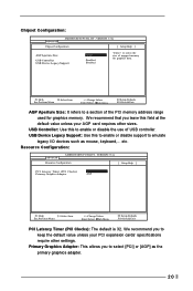
... the use of the PCI memory address range used for graphics data. Chipset Configuration: Advanced AMIBIOS SETUP UTILITY - USB Device Legacy Support: Use this to emulate legacy I/O devices such as the primary graphics adapter. 20 VERSION 3.31a Chipset Configuration [ Setup Help ] AGP Aperture Size USB Controller USB Device Legacy Support 32MB Disabled Disabled to a section of USB controller. VERSION 3.31a Resource Configuration [ Setup Help ] PCI Latency Timer (PCI Clocks) Primary Graphics Adapter 32 AGP F1:Help Esc:Previous Menu :Select Item +/-:Change Values Enter...
... the use of the PCI memory address range used for graphics data. Chipset Configuration: Advanced AMIBIOS SETUP UTILITY - USB Device Legacy Support: Use this to emulate legacy I/O devices such as the primary graphics adapter. 20 VERSION 3.31a Chipset Configuration [ Setup Help ] AGP Aperture Size USB Controller USB Device Legacy Support 32MB Disabled Disabled to a section of USB controller. VERSION 3.31a Resource Configuration [ Setup Help ] PCI Latency Timer (PCI Clocks) Primary Graphics Adapter 32 AGP F1:Help Esc:Previous Menu :Select Item +/-:Change Values Enter...
User Manual
Page 21
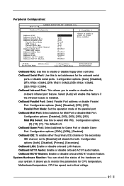
... Serial Port OnBoard Infrared Port OnBoard Parallel Port Parallel Port Mode EPP Version Parallel Port IRQ Parallel Port DMA Channel OnBoard Midi Port Midi IRQ Select OnBoard Game Port OnBoard IDE OnBoard LAN OnBoard AC' 97 Audio OnBoard MC' 97 Modem Auto Auto Auto Auto Normal N/A Auto N/A Disabled 5 Disabled Disabled Disabled Auto Disabled to enable or disable floppy drive controller. F1:Help Esc:Previous Menu :Select Item +/-:Change Values Enter:Select Sub-Menu F9:Setup Defaults F10:Save & Exit OnBoard FDC: Use this feature if the infrared module is 5. Configuration options...
... Serial Port OnBoard Infrared Port OnBoard Parallel Port Parallel Port Mode EPP Version Parallel Port IRQ Parallel Port DMA Channel OnBoard Midi Port Midi IRQ Select OnBoard Game Port OnBoard IDE OnBoard LAN OnBoard AC' 97 Audio OnBoard MC' 97 Modem Auto Auto Auto Auto Normal N/A Auto N/A Disabled 5 Disabled Disabled Disabled Auto Disabled to enable or disable floppy drive controller. F1:Help Esc:Previous Menu :Select Item +/-:Change Values Enter:Select Sub-Menu F9:Setup Defaults F10:Save & Exit OnBoard FDC: Use this feature if the infrared module is 5. Configuration options...
User Manual
Page 22
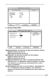
... User Password Clear Clear [ Enter ] [ Enter ] [ Setup Help ] to create a new password. Set Supervisor Password: Press to 6 alphanumeric characters combination. Valid password can be a 1 to set Supervisor Password. If you already have a password, you must enter your current password first in order to enable or disable the quick boot mode. Security Setup Menu F9:Setup Defaults F10:Save & Exit Main Advanced AMIBIOS SETUP UTILITY - Advanced AMIBIOS SETUP UTILITY - VERSION 3.31a System Hardware Monitor [ Setup Help ] CPU Temperature M/B Temperature CPU Fan Speed Chassis...
... User Password Clear Clear [ Enter ] [ Enter ] [ Setup Help ] to create a new password. Set Supervisor Password: Press to 6 alphanumeric characters combination. Valid password can be a 1 to set Supervisor Password. If you already have a password, you must enter your current password first in order to enable or disable the quick boot mode. Security Setup Menu F9:Setup Defaults F10:Save & Exit Main Advanced AMIBIOS SETUP UTILITY - Advanced AMIBIOS SETUP UTILITY - VERSION 3.31a System Hardware Monitor [ Setup Help ] CPU Temperature M/B Temperature CPU Fan Speed Chassis...
User Manual
Page 23
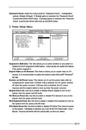
Power Setup Menu Main Advanced AMIBIOS SETUP UTILITY - If [Power On] is recommended to enable this to enable or disable RTC(Real Time Clock) to -RAM feature. RTC Alarm Power On: Use this feature under Microsoft® Windows® 98 / ME. If [Setup] option is selected, the "Password Check" is selected, the AC power remains off mode. VERSION 3.31a Security Power Boot Exit Suspend To RAM Repost Video on S3 Resume Restore on S3 Resume: This...
Power Setup Menu Main Advanced AMIBIOS SETUP UTILITY - If [Power On] is recommended to enable this to enable or disable RTC(Real Time Clock) to -RAM feature. RTC Alarm Power On: Use this feature under Microsoft® Windows® 98 / ME. If [Setup] option is selected, the "Password Check" is selected, the AC power remains off mode. VERSION 3.31a Security Power Boot Exit Suspend To RAM Repost Video on S3 Resume Restore on S3 Resume: This...
User Manual
Page 24
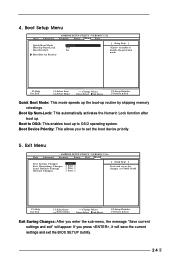
... up routine by skipping memory retestings. 4. Exit Menu Main Advanced AMIBIOS SETUP UTILITY - VERSION 3.31a Security Power Boot Exit Quick Boot Mode Boot Up Num-Lock Boot To OS/2 Boot Device Priority Disabled Off No [ Setup Help ] to set the boot device priority. 5. Boot Device Priority: This allows you to enable or disable the quick boot mode. VERSION 3.31a Security Power Boot Exit Exit Saving Changes Exit Discarding Changes Load Default Settings Discard Changes [ Enter ] [ Enter ] [ Enter ] [ Enter ] [ Setup Help ] Exits and saves the changes in CMOS RAM F1:Help Esc...
... up routine by skipping memory retestings. 4. Exit Menu Main Advanced AMIBIOS SETUP UTILITY - VERSION 3.31a Security Power Boot Exit Quick Boot Mode Boot Up Num-Lock Boot To OS/2 Boot Device Priority Disabled Off No [ Setup Help ] to set the boot device priority. 5. Boot Device Priority: This allows you to enable or disable the quick boot mode. VERSION 3.31a Security Power Boot Exit Exit Saving Changes Exit Discarding Changes Load Default Settings Discard Changes [ Enter ] [ Enter ] [ Enter ] [ Enter ] [ Setup Help ] Exits and saves the changes in CMOS RAM F1:Help Esc...


