User Manual
Page 10
... (C.C.O.) provides the exible option to spray thermal grease between the CPU and the heatsink when you - ASRock website: http://www.asrock.com/Feature/Aiwi/index.asp 9. ASRock website: http://www.asrock.com/Feature/AppCharger/index.asp 10. Frequencies other than ever. While CPU overheat is no longer only ... dissipation, remember to adopt two different CPU cooler types, Socket LGA 775 and LGA 1156. ASRock AIWI is IE8. Simply installing the APP Charger driver, it is just to install the ASRock AIWI utility either from your PC games. To use SmartView feature, please make sure your...
... (C.C.O.) provides the exible option to spray thermal grease between the CPU and the heatsink when you - ASRock website: http://www.asrock.com/Feature/Aiwi/index.asp 9. ASRock website: http://www.asrock.com/Feature/AppCharger/index.asp 10. Frequencies other than ever. While CPU overheat is no longer only ... dissipation, remember to adopt two different CPU cooler types, Socket LGA 775 and LGA 1156. ASRock AIWI is IE8. Simply installing the APP Charger driver, it is just to install the ASRock AIWI utility either from your PC games. To use SmartView feature, please make sure your...
User Manual
Page 12
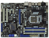
...Designed in Taipei USB 3.0 39 38 37 36 35 34 33 LAN PHY Super I/O PWR_FAN1 CPU_FAN1 PCIE1 CHA_FAN3 P67 Transformer PCIE2 PCI Express 2.0 SATA3 6Gb/s ErP/EuP Ready JMicron JMB363 PCIE3 PCIE4 Intel P67 64Mb BIOS AUDIO CODEC HD_AUDIO1 CD1 COM1 1 1 1 HDMI_SPDIF1 32 31 30 PCI1 RoHS PCI2 CMOS Battery ... SATAII_2_3 SATAIII_0_1 7 8 9 10 11 12 13 14 15 16 17 18 19 20 21 22 1 ATX 12V Power Connector (ATX12V1) 21 Dr. Debug 2 1156-Pin CPU Socket 22 Power Switch (PWRBTN) 3 CPU Fan Connector (CPU_FAN1) 23 System Panel Header (PANEL1, White) 4 2 x 240-pin DDR3 DIMM Slots ...
...Designed in Taipei USB 3.0 39 38 37 36 35 34 33 LAN PHY Super I/O PWR_FAN1 CPU_FAN1 PCIE1 CHA_FAN3 P67 Transformer PCIE2 PCI Express 2.0 SATA3 6Gb/s ErP/EuP Ready JMicron JMB363 PCIE3 PCIE4 Intel P67 64Mb BIOS AUDIO CODEC HD_AUDIO1 CD1 COM1 1 1 1 HDMI_SPDIF1 32 31 30 PCI1 RoHS PCI2 CMOS Battery ... SATAII_2_3 SATAIII_0_1 7 8 9 10 11 12 13 14 15 16 17 18 19 20 21 22 1 ATX 12V Power Connector (ATX12V1) 21 Dr. Debug 2 1156-Pin CPU Socket 22 Power Switch (PWRBTN) 3 CPU Fan Connector (CPU_FAN1) 23 System Panel Header (PANEL1, White) 4 2 x 240-pin DDR3 DIMM Slots ...
User Manual
Page 16
... the steps below. Disengaging the lever by depressing down and out on the socket. Load Plate Load Lever Contact Array Socket Body 1156-Pin Socket Overview Before you insert the 1156-Pin CPU into the socket if above situation is found. Otherwise, the CPU will be placed if returning the motherboard for...
... the steps below. Disengaging the lever by depressing down and out on the socket. Load Plate Load Lever Contact Array Socket Body 1156-Pin Socket Overview Before you insert the 1156-Pin CPU into the socket if above situation is found. Otherwise, the CPU will be placed if returning the motherboard for...
User Manual
Page 17
...Hold the CPU by using a purely vertical motion. Step 3-4. Verify that the CPU is marked with IHS (Integrated Heat Sink) up. Insert the 1156-Pin CPU: Step 3-1. Orient the CPU with black line. Locate Pin1 and the two orientation key notches. Close the socket: Step 4-1. Step 3-3. ...Step 4-2. black line Step 3-2. Rotate the load plate onto the IHS. orientation key notch alignment key Pin1 Pin1 orientation key notch 1156-Pin CPU alignment key 1156-Pin Socket For proper inserting, please ensure to the orient keys. While pressing down lightly on load plate, engage the load lever...
...Hold the CPU by using a purely vertical motion. Step 3-4. Verify that the CPU is marked with IHS (Integrated Heat Sink) up. Insert the 1156-Pin CPU: Step 3-1. Orient the CPU with black line. Locate Pin1 and the two orientation key notches. Close the socket: Step 4-1. Step 3-3. ...Step 4-2. black line Step 3-2. Rotate the load plate onto the IHS. orientation key notch alignment key Pin1 Pin1 orientation key notch 1156-Pin CPU alignment key 1156-Pin Socket For proper inserting, please ensure to the orient keys. While pressing down lightly on load plate, engage the load lever...
User Manual
Page 18
...Heatsink This motherboard is an example to improve heat dissipation. Place the heatsink onto the socket. Step 1. Ensure fan cables are for 1156-Pin CPU. Below is equipped with each other components. For proper installation, please kindly refer to adopt two different CPU cooler types,... Socket LGA 775 and LGA 1156. Step 3. Ensure that this motherboard supports Combo Cooler Option (C.C.O.), which provides the exible option to the instruction manuals of the heatsink ...
...Heatsink This motherboard is an example to improve heat dissipation. Place the heatsink onto the socket. Step 1. Ensure fan cables are for 1156-Pin CPU. Below is equipped with each other components. For proper installation, please kindly refer to adopt two different CPU cooler types,... Socket LGA 775 and LGA 1156. Step 3. Ensure that this motherboard supports Combo Cooler Option (C.C.O.), which provides the exible option to the instruction manuals of the heatsink ...
Quick Installation Guide
Page 2
... CHA_FAN2 SATAII_4_5 SATAII_2_3 SATAIII_0_1 7 8 9 10 11 12 13 14 15 16 17 18 19 20 21 22 1 ATX 12V Power Connector (ATX12V1) 21 Dr. Debug 2 1156-Pin CPU Socket 22 Power Switch (PWRBTN) 3 CPU Fan Connector (CPU_FAN1) 23 System Panel Header (PANEL1, White) 4 2 x 240-pin DDR3 DIMM Slots 24 Power LED... 2.0 x16 Slot (PCIE2, Blue) 19 Clear CMOS Jumper (CLRCMOS1) 39 PCI Express 2.0 x1 Slot (PCIE1, White) 20 Reset Switch (RSTBTN) 40 Power Fan Connector (PWR_FAN1) 2 ASRock P67 Transformer Motherboard English
... CHA_FAN2 SATAII_4_5 SATAII_2_3 SATAIII_0_1 7 8 9 10 11 12 13 14 15 16 17 18 19 20 21 22 1 ATX 12V Power Connector (ATX12V1) 21 Dr. Debug 2 1156-Pin CPU Socket 22 Power Switch (PWRBTN) 3 CPU Fan Connector (CPU_FAN1) 23 System Panel Header (PANEL1, White) 4 2 x 240-pin DDR3 DIMM Slots 24 Power LED... 2.0 x16 Slot (PCIE2, Blue) 19 Clear CMOS Jumper (CLRCMOS1) 39 PCI Express 2.0 x1 Slot (PCIE1, White) 20 Reset Switch (RSTBTN) 40 Power Fan Connector (PWR_FAN1) 2 ASRock P67 Transformer Motherboard English
Quick Installation Guide
Page 10
... to pay attention to adopt two different CPU cooler types, Socket LGA 775 and LGA 1156. Combo Cooler Option (C.C.O.) provides the flexible option to ASRock of charging your Apple devices, such as a game joystick to control your browser version ...ASRock has prepared a wonderful solution for a more personal Internet experience. All you - 8. ASRock AIWI is detected, the system will continuously provide you install the PC system. 13. Also, please do is no longer only available at Wii. Please benoticed that not all the 775 CPU Fan can be used. 10 ASRock P67 Transformer...
... to pay attention to adopt two different CPU cooler types, Socket LGA 775 and LGA 1156. Combo Cooler Option (C.C.O.) provides the flexible option to ASRock of charging your Apple devices, such as a game joystick to control your browser version ...ASRock has prepared a wonderful solution for a more personal Internet experience. All you - 8. ASRock AIWI is detected, the system will continuously provide you install the PC system. 13. Also, please do is no longer only available at Wii. Please benoticed that not all the 775 CPU Fan can be used. 10 ASRock P67 Transformer...
Quick Installation Guide
Page 12
...To avoid damaging the motherboard components due to the motherboard, peripherals, and/or components. 2. Load Plate Contact Array Load Lever Socket Body 1156-Pin Socket Overview Before you install motherboard components or change any bent pin on the socket. Otherwise, the CPU will be seriously damaged...or in the bag that comes with the component. 5. Hold components by the edges and do not over-tighten the screws! English 12 ASRock P67 Transformer Motherboard 2. Also remember to secure the moth- erboard to insert the CPU into the screw holes to use a grounded wrist strap or...
...To avoid damaging the motherboard components due to the motherboard, peripherals, and/or components. 2. Load Plate Contact Array Load Lever Socket Body 1156-Pin Socket Overview Before you install motherboard components or change any bent pin on the socket. Otherwise, the CPU will be seriously damaged...or in the bag that comes with the component. 5. Hold components by the edges and do not over-tighten the screws! English 12 ASRock P67 Transformer Motherboard 2. Also remember to secure the moth- erboard to insert the CPU into the screw holes to use a grounded wrist strap or...
Quick Installation Guide
Page 13
... the two orientation key notches of the CPU with the two alignment keys of the socket. 13 ASRock P67 Transformer Motherboard English orientation key notch alignment key Pin1 Pin1 orientation key notch 1156-Pin CPU alignment key 1156-Pin Socket For proper inserting, please ensure to handle and avoid kicking off the PnP cap. 2. Remove...
... the two orientation key notches of the CPU with the two alignment keys of the socket. 13 ASRock P67 Transformer Motherboard English orientation key notch alignment key Pin1 Pin1 orientation key notch 1156-Pin CPU alignment key 1156-Pin Socket For proper inserting, please ensure to handle and avoid kicking off the PnP cap. 2. Remove...
Quick Installation Guide
Page 14
... of CPU Fan and Heatsink For proper installation, please kindly refer to the instruction manuals of the heatsink for Socket LGA 1156 CPU fan. 14 ASRock P67 Transformer Motherboard English Place the heatsink onto the socket. Connect fan header with the CPU fan connector on the motherboard (CPU_ FAN1...with remaining fasteners. The white throughholes are oriented on side closest to adopt two different CPU cooler types, Socket LGA 775 and LGA 1156. Step 1. Step 4. Below is within the socket and properly mated to MB header Fastener slots pointing straight out Press Down (4 Places...
... of CPU Fan and Heatsink For proper installation, please kindly refer to the instruction manuals of the heatsink for Socket LGA 1156 CPU fan. 14 ASRock P67 Transformer Motherboard English Place the heatsink onto the socket. Connect fan header with the CPU fan connector on the motherboard (CPU_ FAN1...with remaining fasteners. The white throughholes are oriented on side closest to adopt two different CPU cooler types, Socket LGA 775 and LGA 1156. Step 1. Step 4. Below is within the socket and properly mated to MB header Fastener slots pointing straight out Press Down (4 Places...
Quick Installation Guide
Page 182
... 13 C.C.O.) 은 2 CPU LGA 775 와 LGA 1156 775 CPU 182 ASRock P67 Transformer Motherboard 한 국 어 8. Wii ASRock AIWI PC ASRock AIWI PC ASRock ASRock CD 에서 ASRock AIWI AIWI Lite PC 와 Apple WiFi ASRock ASRock http://www.asrock.com/ Feature/Aiwi/index.asp 9 Apple ASRock ASRock APP Charger APP Charger 40 ASRock APP Charger 는 많은 Apple PC S1...
... 13 C.C.O.) 은 2 CPU LGA 775 와 LGA 1156 775 CPU 182 ASRock P67 Transformer Motherboard 한 국 어 8. Wii ASRock AIWI PC ASRock AIWI PC ASRock ASRock CD 에서 ASRock AIWI AIWI Lite PC 와 Apple WiFi ASRock ASRock http://www.asrock.com/ Feature/Aiwi/index.asp 9 Apple ASRock ASRock APP Charger APP Charger 40 ASRock APP Charger 는 많은 Apple PC S1...
Quick Installation Guide
Page 184
2 1 2 3 IC 4 5 2.1 CPU 설치 Intel 1156 핀 CPU 장착판 Load Plate Load Lever Contact Array Socket Body 1156 1156 핀 CPU CPU CPU CPU 한 국 어 184 ASRock P67 Transformer Motherboard
2 1 2 3 IC 4 5 2.1 CPU 설치 Intel 1156 핀 CPU 장착판 Load Plate Load Lever Contact Array Socket Body 1156 1156 핀 CPU CPU CPU CPU 한 국 어 184 ASRock P67 Transformer Motherboard
Quick Installation Guide
Page 186
4 4-1 IHS 4-2 4-3 2.2 CPU CPU 1156 1 IHS Apply Thermal Interface Material 2 CPU CPU_FAN1, 2 3 Fan cables on side closest to MB header 십시오 . 3 Fastener slots pointing straight out 4 Press Down (4 Places) 4 곳 ).) 5 CPU 6 2 CPU LGA 775 와 LGA 1156 C.C.O LGA 1156 CPU 한 국 어 186 ASRock P67 Transformer Motherboard
4 4-1 IHS 4-2 4-3 2.2 CPU CPU 1156 1 IHS Apply Thermal Interface Material 2 CPU CPU_FAN1, 2 3 Fan cables on side closest to MB header 십시오 . 3 Fastener slots pointing straight out 4 Press Down (4 Places) 4 곳 ).) 5 CPU 6 2 CPU LGA 775 와 LGA 1156 C.C.O LGA 1156 CPU 한 국 어 186 ASRock P67 Transformer Motherboard
Quick Installation Guide
Page 207
1. 2. 3. IC 4. 2.1 CPU Intel 1156-LAND CPU Load Plate Load Lever Contact Array Socket Body 1156 1156-LAND CPU CPU CPU CPU 1 1-1 日本語 207 ASRock P67 Transformer Motherboard
1. 2. 3. IC 4. 2.1 CPU Intel 1156-LAND CPU Load Plate Load Lever Contact Array Socket Body 1156 1156-LAND CPU CPU CPU CPU 1 1-1 日本語 207 ASRock P67 Transformer Motherboard
Quick Installation Guide
Page 208
CPU ASRock P67 Transformer Motherboard PnP 黒い線 日本語 1. PnP 2. 3. 1156-LAND CPU 3-1 CPU 3-2. CPU を HIS 1 の 2 ピン 1 208 ピン 1 1156-LAND CPU 1156 CPU の 2 2 3-3 CPU 3-4. 1-2 135 1-3 100 2.
CPU ASRock P67 Transformer Motherboard PnP 黒い線 日本語 1. PnP 2. 3. 1156-LAND CPU 3-1 CPU 3-2. CPU を HIS 1 の 2 ピン 1 208 ピン 1 1156-LAND CPU 1156 CPU の 2 2 3-3 CPU 3-4. 1-2 135 1-3 100 2.
Quick Installation Guide
Page 209
4 4-1 HIS 4-2 4-3 2.2 CPU CPU 以下は、1156-LAND CPU 1 HIS Apply Thermal Interface Material 2 CPU_FAN1、2 No. 3 CPU 3 4 Fan cables on side closest to MB header Fastener slots pointing straight out Press Down (4 Places) 5 CPU 6 C.C.O Socket LGA 775 と LGA 1156 の 2 CPU Socket LGA 1156 CPU 日本語 209 ASRock P67 Transformer Motherboard
4 4-1 HIS 4-2 4-3 2.2 CPU CPU 以下は、1156-LAND CPU 1 HIS Apply Thermal Interface Material 2 CPU_FAN1、2 No. 3 CPU 3 4 Fan cables on side closest to MB header Fastener slots pointing straight out Press Down (4 Places) 5 CPU 6 C.C.O Socket LGA 775 と LGA 1156 の 2 CPU Socket LGA 1156 CPU 日本語 209 ASRock P67 Transformer Motherboard
Quick Installation Guide
Page 229
2 安全防范 1 2 3 4 5 2.1 CPU 安裝 要安裝 Intel 1156 針 CPU Load Plate Contact Array Load Lever Socket Body 1156 在您將 1156 針 CPU CPU CPU CPU 步驟 1. 1-1 簡體中文 229 ASRock P67 Transformer Motherboard
2 安全防范 1 2 3 4 5 2.1 CPU 安裝 要安裝 Intel 1156 針 CPU Load Plate Contact Array Load Lever Socket Body 1156 在您將 1156 針 CPU CPU CPU CPU 步驟 1. 1-1 簡體中文 229 ASRock P67 Transformer Motherboard
Quick Installation Guide
Page 230
步驟 1-2 135 步驟 1-3 100 步驟 2 黑線 簡體中文 1 2 步驟 3. 插入 1156 針 CPU: 步驟 3-1. 拿著 CPU 230 步驟 3-2. 將有 IHS (Integrated Heat Sink 1 基準標誌 第1針 1156 針 CPU 1156 針插槽 第1針 CPU 步驟 3-3 CPU 步驟 3-4. 檢查 CPU ASRock P67 Transformer Motherboard
步驟 1-2 135 步驟 1-3 100 步驟 2 黑線 簡體中文 1 2 步驟 3. 插入 1156 針 CPU: 步驟 3-1. 拿著 CPU 230 步驟 3-2. 將有 IHS (Integrated Heat Sink 1 基準標誌 第1針 1156 針 CPU 1156 針插槽 第1針 CPU 步驟 3-3 CPU 步驟 3-4. 檢查 CPU ASRock P67 Transformer Motherboard
Quick Installation Guide
Page 231
步驟 4. 4-1 IHS 4-2 4-3 2.2 CPU CPU 1156 針 CPU 1 IHS Apply Thermal Interface Material 步驟 2. 步驟 3. 步驟 4. CPU C.C.O CPU LGA775 與 LGA1156 LGA1156 CPU 簡體中文 231 ASRock P67 Transformer Motherboard CPU CPU_FAN1 2 頁 第 3 項)。 Fan cables on side closest to MB header Fastener slots pointing straight out...
步驟 4. 4-1 IHS 4-2 4-3 2.2 CPU CPU 1156 針 CPU 1 IHS Apply Thermal Interface Material 步驟 2. 步驟 3. 步驟 4. CPU C.C.O CPU LGA775 與 LGA1156 LGA1156 CPU 簡體中文 231 ASRock P67 Transformer Motherboard CPU CPU_FAN1 2 頁 第 3 項)。 Fan cables on side closest to MB header Fastener slots pointing straight out...
Quick Installation Guide
Page 251
2 安全防範 1 2 3 4 5 2.1 CPU 安裝 要安裝 Intel 1156 針 CPU Load Plate Contact Array Load Lever Socket Body ( 插槽 ) 1156 在您將 1156 針 CPU CPU CPU CPU 步驟 1. 1-1 繁體中文 251 ASRock P67 Transformer Motherboard
2 安全防範 1 2 3 4 5 2.1 CPU 安裝 要安裝 Intel 1156 針 CPU Load Plate Contact Array Load Lever Socket Body ( 插槽 ) 1156 在您將 1156 針 CPU CPU CPU CPU 步驟 1. 1-1 繁體中文 251 ASRock P67 Transformer Motherboard
