
User Manual
Page 3
Contents 1 Introduction 5 1.1 Package Contents 5 1.2 Specifications 6 1.3 Motherboard Layout 14 1.4 I/O Panel 15 2 Installation 17 2.1 Screw Holes 17 2.2 Pre-installation Precautions 17 2.3 CPU Installation 18 2.4 Installation of Heatsink and CPU fan 20 2.5 Installation of Memory Modules (DIMM 21 2.6 Expansion Slots (PCI and PCI Express Slots 23 2.7 SLITM and Quad SLITM Operation Guide 24 2.8 CrossFireXTM...
Contents 1 Introduction 5 1.1 Package Contents 5 1.2 Specifications 6 1.3 Motherboard Layout 14 1.4 I/O Panel 15 2 Installation 17 2.1 Screw Holes 17 2.2 Pre-installation Precautions 17 2.3 CPU Installation 18 2.4 Installation of Heatsink and CPU fan 20 2.5 Installation of Memory Modules (DIMM 21 2.6 Expansion Slots (PCI and PCI Express Slots 23 2.7 SLITM and Quad SLITM Operation Guide 24 2.8 CrossFireXTM...

User Manual
Page 4
... Guide 58 3 UEFI SETUP UTILITY 62 3.1 Introduction 62 3.1.1 UEFI Menu Bar 62 3.1.2 Navigation Keys 63 3.2 Main Screen 63 3.3 OC Tweaker Screen 64 3.4 Advanced Screen 67 3.4.1 CPU Configuration 68 3.4.2 North Bridge Configuration 70 3.4.3 South Bridge Configuration 71 3.4.4 Storage Configuration 72 3.4.5 Super IO Confi...
... Guide 58 3 UEFI SETUP UTILITY 62 3.1 Introduction 62 3.1.1 UEFI Menu Bar 62 3.1.2 Navigation Keys 63 3.2 Main Screen 63 3.3 OC Tweaker Screen 64 3.4 Advanced Screen 67 3.4.1 CPU Configuration 68 3.4.2 North Bridge Configuration 70 3.4.3 South Bridge Configuration 71 3.4.4 Storage Configuration 72 3.4.5 Super IO Confi...
User Manual
Page 5
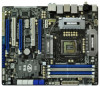
... and CPU support lists on ASRock website without notice. ASRock website http://www.asrock.com If you require technical support related to this manual, chapter 1 and 2 contain introduction of the Support CD. www.asrock.com/support/index.asp 1.1 Package Contents ASRock P67 Extreme6 Motherboard (ATX Form Factor: 12.0-in x 9.6-in, 30.5 cm x 24.4 cm) ASRock P67 Extreme6 Quick Installation Guide ASRock P67 Extreme6 Support...
... and CPU support lists on ASRock website without notice. ASRock website http://www.asrock.com If you require technical support related to this manual, chapter 1 and 2 contain introduction of the Support CD. www.asrock.com/support/index.asp 1.1 Package Contents ASRock P67 Extreme6 Motherboard (ATX Form Factor: 12.0-in x 9.6-in, 30.5 cm x 24.4 cm) ASRock P67 Extreme6 Quick Installation Guide ASRock P67 Extreme6 Support...

User Manual
Page 6
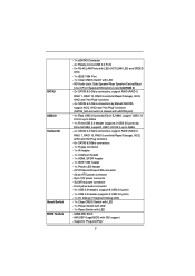
...Polymer Capacitors) - Dual Channel DDR3 Memory Technology (see CAUTION 4) - Supports Energy Efficient Ethernet 802.3az - Intel® P67 - Max. Supports Dual LAN with Content Protection (Realtek ALC892 Audio Codec) - Advanced V16 + 2 Power Phase Design - Supports NVIDIA...® Quad SLITM and SLITM - 7.1 CH HD Audio with Teaming function I /O - 1.2 Specifications Platform CPU Chipset Memory Expansion Slot Audio LAN Rear Panel I /O Panel - 1 x PS/2 Mouse Port - 1 x PS/2 Keyboard Port - 1 x Coaxial SPDIF Out Port ...
...Polymer Capacitors) - Dual Channel DDR3 Memory Technology (see CAUTION 4) - Supports Energy Efficient Ethernet 802.3az - Intel® P67 - Max. Supports Dual LAN with Content Protection (Realtek ALC892 Audio Codec) - Advanced V16 + 2 Power Phase Design - Supports NVIDIA...® Quad SLITM and SLITM - 7.1 CH HD Audio with Teaming function I /O - 1.2 Specifications Platform CPU Chipset Memory Expansion Slot Audio LAN Rear Panel I /O Panel - 1 x PS/2 Mouse Port - 1 x PS/2 Keyboard Port - 1 x Coaxial SPDIF Out Port ...
User Manual
Page 7
... 2 USB 3.0 ports) - 1 x Dr. Debug (7-Segment Debug LED) - 1 x Clear CMOS Switch with LED - 1 x Power Switch with LED - 1 x Reset Switch with GUI support - Supports "Plug and Play" 7 CPU/Chassis/Power FAN connector - 24 pin ATX power connector - 8 pin 12V power connector - SLI/XFire power connector - AMI UEFI Legal BIOS with LED - 64Mb AMI...
... 2 USB 3.0 ports) - 1 x Dr. Debug (7-Segment Debug LED) - 1 x Clear CMOS Switch with LED - 1 x Power Switch with LED - 1 x Reset Switch with GUI support - Supports "Plug and Play" 7 CPU/Chassis/Power FAN connector - 24 pin ATX power connector - 8 pin 12V power connector - SLI/XFire power connector - AMI UEFI Legal BIOS with LED - 64Mb AMI...
User Manual
Page 8
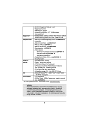
...For detailed product information, please visit our website: http://www.asrock.com WARNING Please realize that there is required) (see CAUTION 10) - Chassis Temperature Sensing - Voltage Monitoring: +12V, +5V, +3.3V, CPU Vcore OS - Overclocking may affect your system stability, or...or using the third-party overclocking tools. ACPI 1.1 Compliance Wake Up Events - SMBIOS 2.3.1 Support - ASRock AIWI (see CAUTION 11) - CPU Frequency Stepless Control (see CAUTION 8) - CPU/Chassis Quiet Fan (Allow Chassis Fan Speed Auto-Adjust by overclocking. 8 Supports jumperfree - OEM and...
...For detailed product information, please visit our website: http://www.asrock.com WARNING Please realize that there is required) (see CAUTION 10) - Chassis Temperature Sensing - Voltage Monitoring: +12V, +5V, +3.3V, CPU Vcore OS - Overclocking may affect your system stability, or...or using the third-party overclocking tools. ACPI 1.1 Compliance Wake Up Events - SMBIOS 2.3.1 Support - ASRock AIWI (see CAUTION 11) - CPU Frequency Stepless Control (see CAUTION 8) - CPU/Chassis Quiet Fan (Allow Chassis Fan Speed Auto-Adjust by overclocking. 8 Supports jumperfree - OEM and...
User Manual
Page 9
... preparing an additional floppy diskette or other complicated flash utility. Your friends then can support DDR3 overclock to access ASRock Instant Flash. Just launch this utility, you can reduce the number of memory modules on the processor. Before you can press...table on page 15 for the operation procedures of "Hyper Threading Technology", please check page 68. 2. ASRock website: http://www.asrock.com 7. CAUTION! 1. About the setting of ASRock Extreme Tuning Utility (AXTU). Only K-Series CPU can load the OC profile to their own system to adjust.
... preparing an additional floppy diskette or other complicated flash utility. Your friends then can support DDR3 overclock to access ASRock Instant Flash. Just launch this utility, you can reduce the number of memory modules on the processor. Before you can press...table on page 15 for the operation procedures of "Hyper Threading Technology", please check page 68. 2. ASRock website: http://www.asrock.com 7. CAUTION! 1. About the setting of ASRock Extreme Tuning Utility (AXTU). Only K-Series CPU can load the OC profile to their own system to adjust.

User Manual
Page 10
... control, it makes your iPhone charged much quickly from App store to control your iPhone/iPod touch. ASRock AIWI utility introduces a new way of the system or damage the CPU. 12. Simply installing the APP Charger driver, it is detected, the system will continuously provide you ...shutdown. With APP Charger driver installed, you to spray thermal grease between the CPU and the heatsink when you resume the system, please check if the CPU fan on -the-go. ASRock website: http://www.asrock.com/Feature/AppCharger/index.asp 10. Frequencies other than before. To improve ...
... control, it makes your iPhone charged much quickly from App store to control your iPhone/iPod touch. ASRock AIWI utility introduces a new way of the system or damage the CPU. 12. Simply installing the APP Charger driver, it is detected, the system will continuously provide you ...shutdown. With APP Charger driver installed, you to spray thermal grease between the CPU and the heatsink when you resume the system, please check if the CPU fan on -the-go. ASRock website: http://www.asrock.com/Feature/AppCharger/index.asp 10. Frequencies other than before. To improve ...

User Manual
Page 14
...64Mb BIOS CrossFireX 45 PCI1 1394a ErP/EuP Ready CLRCMOS1 44 PCIE3 1 CMOS Intel Super I/O Battery PCI Express 2.0 P67 SATA3_0_1 Front USB 3.0 SATA3_M3_M4 SATA3_M1_M2 43 42 41 40 39 PCIE4 P67 Extreme6 PCI2 Designed in Taipei 1 HDMI_SPDIF1 IR1 PCIE5 HD_AUDIO1 1 FLOPPY1 COM1 USB3_2_3 1 1 Dr. Debug USB 3.0 USB6_7 ... 24 25 26 38 37 36 35 34 33 32 31 30 29 28 27 1 ATX 12V Power Connector (ATX12V1) 2 1155-Pin CPU Socket 3 CPU Fan Connector (CPU_FAN2) 4 CPU Fan Connector (CPU_FAN1) 5 2 x 240-pin DDR3 DIMM Slots (Dual Channel: DDR3_A1, DDR3_B1, Blue) 6 2 x 240-pin DDR3...
...64Mb BIOS CrossFireX 45 PCI1 1394a ErP/EuP Ready CLRCMOS1 44 PCIE3 1 CMOS Intel Super I/O Battery PCI Express 2.0 P67 SATA3_0_1 Front USB 3.0 SATA3_M3_M4 SATA3_M1_M2 43 42 41 40 39 PCIE4 P67 Extreme6 PCI2 Designed in Taipei 1 HDMI_SPDIF1 IR1 PCIE5 HD_AUDIO1 1 FLOPPY1 COM1 USB3_2_3 1 1 Dr. Debug USB 3.0 USB6_7 ... 24 25 26 38 37 36 35 34 33 32 31 30 29 28 27 1 ATX 12V Power Connector (ATX12V1) 2 1155-Pin CPU Socket 3 CPU Fan Connector (CPU_FAN2) 4 CPU Fan Connector (CPU_FAN1) 5 2 x 240-pin DDR3 DIMM Slots (Dual Channel: DDR3_A1, DDR3_B1, Blue) 6 2 x 240-pin DDR3...

User Manual
Page 18
... open position at approximately 135 degrees. Step 1. Step 1-2. Step 1-3. Remove PnP Cap (Pick and Place Cap). 1. Step 2. Otherwise, the CPU will be placed if returning the motherboard for after service. 18 It is found. Disengaging the lever by depressing down and out on the socket... must be seriously damaged. Rotate the load plate to handle and avoid kicking off the PnP cap. 2. 2.3 CPU Installation For the installation of Intel 1155-Pin CPU, please follow the steps below. Load Plate Load Lever Contact Array Socket Body 1155-Pin Socket Overview Before you ...
... open position at approximately 135 degrees. Step 1. Step 1-2. Step 1-3. Remove PnP Cap (Pick and Place Cap). 1. Step 2. Otherwise, the CPU will be placed if returning the motherboard for after service. 18 It is found. Disengaging the lever by depressing down and out on the socket... must be seriously damaged. Rotate the load plate to handle and avoid kicking off the PnP cap. 2. 2.3 CPU Installation For the installation of Intel 1155-Pin CPU, please follow the steps below. Load Plate Load Lever Contact Array Socket Body 1155-Pin Socket Overview Before you ...

User Manual
Page 19
... two orientation key notches of the socket. Close the socket: Step 4-1. Insert the 1155-Pin CPU: Step 3-1. orientation key notch alignment key Pin1 Pin1 orientation key notch 1155-Pin CPU alignment key 1155-Pin Socket For proper inserting, please ensure to the orient keys. Verify that... the CPU is marked with the two alignment keys of the CPU with black line. Step 4-2. Step 4. Orient the CPU with IHS (Integrated Heat Sink) up. Step 3. Locate Pin1 and the two orientation key...
... two orientation key notches of the socket. Close the socket: Step 4-1. Insert the 1155-Pin CPU: Step 3-1. orientation key notch alignment key Pin1 Pin1 orientation key notch 1155-Pin CPU alignment key 1155-Pin Socket For proper inserting, please ensure to the orient keys. Verify that... the CPU is marked with the two alignment keys of the CPU with black line. Step 4-2. Step 4. Orient the CPU with IHS (Integrated Heat Sink) up. Step 3. Locate Pin1 and the two orientation key...

User Manual
Page 20
... Connect fan header with fan operation or contact other . Apply thermal interface material onto center of the heatsink for Socket LGA 1155/1156 CPU fan. 20 Apply Thermal Interface Material Step 2. Step 3. Place the heatsink onto the socket. Rotate the fastener clockwise, then press down... the fasteners without rotating them clockwise, the heatsink cannot be noticed that the CPU and the heatsink are securely fastened and in good contact with tie-wrap to install and lock. Secure excess cable with each other ...
... Connect fan header with fan operation or contact other . Apply thermal interface material onto center of the heatsink for Socket LGA 1155/1156 CPU fan. 20 Apply Thermal Interface Material Step 2. Step 3. Place the heatsink onto the socket. Rotate the fastener clockwise, then press down... the fasteners without rotating them clockwise, the heatsink cannot be noticed that the CPU and the heatsink are securely fastened and in good contact with tie-wrap to install and lock. Secure excess cable with each other ...

User Manual
Page 38
... +12V CHA_FAN_SPEED (3-pin CHA_FAN2) (see p.14 No. 4) 3 4 GND +12V CHA_FAN_SPEED GND +12V PWR_FAN_SPEED GND +12V CPU_FAN_SPEED FAN_SPEED_CONTROL Please connect the CPU fan cable to the connector and match the black wire to this header to indicate system power status. When connecting your chassis front panel module...connectors and match the black wire to the ground pin. (3-pin CHA_FAN3) (see p.14 No. 10) (3-pin PWR_FAN1) (see p.14 No. 9) CPU Fan Connectors (4-pin CPU_FAN1) 1 2 (see p.14 No. 29) Please connect the chassis speaker to the hard drive activity LED on when the ...
... +12V CHA_FAN_SPEED (3-pin CHA_FAN2) (see p.14 No. 4) 3 4 GND +12V CHA_FAN_SPEED GND +12V PWR_FAN_SPEED GND +12V CPU_FAN_SPEED FAN_SPEED_CONTROL Please connect the CPU fan cable to the connector and match the black wire to this header to indicate system power status. When connecting your chassis front panel module...connectors and match the black wire to the ground pin. (3-pin CHA_FAN3) (see p.14 No. 10) (3-pin PWR_FAN1) (see p.14 No. 9) CPU Fan Connectors (4-pin CPU_FAN1) 1 2 (see p.14 No. 29) Please connect the chassis speaker to the hard drive activity LED on when the ...

User Manual
Page 39
... 1 13 ATX 12V Power Connector (8-pin ATX12V1) (see p.14 No. 1) 8 5 4 1 Please connect an ATX 12V power supply to the CPU fan connector on this motherboard, please connect it can still work successfully even without the fan speed control function. Though this motherboard provides 4-Pin... CPU fan (Quiet Fan) support, the 3-Pin CPU fan still can work if you plan to connect the 3-Pin CPU fan to this connector. Pin 1-3 Connected (3-pin CPU_FAN2) (see p.14 No. 3) ...
... 1 13 ATX 12V Power Connector (8-pin ATX12V1) (see p.14 No. 1) 8 5 4 1 Please connect an ATX 12V power supply to the CPU fan connector on this motherboard, please connect it can still work successfully even without the fan speed control function. Though this motherboard provides 4-Pin... CPU fan (Quiet Fan) support, the 3-Pin CPU fan still can work if you plan to connect the 3-Pin CPU fan to this connector. Pin 1-3 Connected (3-pin CPU_FAN2) (see p.14 No. 3) ...

User Manual
Page 43
... Microcode not loaded PEI Core is started Pre-memory CPU initialization is started Pre-memory CPU initialization (CPU module specific) Pre-memory CPU initialization (CPU module specific) Pre-memory CPU initialization (CPU module specific) Pre-memory North Bridge initialization is...ASL Status Codes section below for ASL (see the diagrams below ) Memory Installed CPU post-memory initialization is started CPU post-memory initialization. Cache initialization CPU post-memory initialization. Programming memory timing information Memory initialization. Status Code 0x00 0x01 ...
... Microcode not loaded PEI Core is started Pre-memory CPU initialization is started Pre-memory CPU initialization (CPU module specific) Pre-memory CPU initialization (CPU module specific) Pre-memory CPU initialization (CPU module specific) Pre-memory North Bridge initialization is...ASL Status Codes section below for ASL (see the diagrams below ) Memory Installed CPU post-memory initialization is started CPU post-memory initialization. Cache initialization CPU post-memory initialization. Programming memory timing information Memory initialization. Status Code 0x00 0x01 ...

User Manual
Page 44
... usable memory detected Unspecified memory initialization error Memory not installed Invalid CPU type or Speed CPU mismatch CPU self test failed or possible CPU cache error CPU micro-code is not found or micro-code update is failed Internal CPU error reset PPI is not available Reserved for future AMI error codes S3 Resume...
... usable memory detected Unspecified memory initialization error Memory not installed Invalid CPU type or Speed CPU mismatch CPU self test failed or possible CPU cache error CPU micro-code is not found or micro-code update is failed Internal CPU error reset PPI is not available Reserved for future AMI error codes S3 Resume...

User Manual
Page 45
... - 0x9F 0xA0 0xA1 0xA2 0xA3 0xA4 0xA5 Installation of the South Bridge Runtime Services CPU DXE initialization is started CPU DXE initialization (CPU module specific) CPU DXE initialization (CPU module specific) CPU DXE initialization (CPU module specific) CPU DXE initialization (CPU module specific) PCI host bridge initialization North Bridge DXE initialization is started North Bridge...
... - 0x9F 0xA0 0xA1 0xA2 0xA3 0xA4 0xA5 Installation of the South Bridge Runtime Services CPU DXE initialization is started CPU DXE initialization (CPU module specific) CPU DXE initialization (CPU module specific) CPU DXE initialization (CPU module specific) CPU DXE initialization (CPU module specific) PCI host bridge initialization North Bridge DXE initialization is started North Bridge...

User Manual
Page 46
... found No Console Input Devices are not available PCI resource allocation error. Out of Resources No Space for future AMI codes OEM BDS initialization codes CPU initialization error North Bridge initialization error South Bridge initialization error Some of NVRAM settings) Reserved for Legacy Option ROM No Console Output Devices are found...
... found No Console Input Devices are not available PCI resource allocation error. Out of Resources No Space for future AMI codes OEM BDS initialization codes CPU initialization error North Bridge initialization error South Bridge initialization error Some of NVRAM settings) Reserved for Legacy Option ROM No Console Output Devices are found...

User Manual
Page 64
... Windows® VistaTM / 7 and want to enable this function, please set this item to [Enabled]. Please note that overclocking may reduce CPU voltage and lead to run faster than marked frequency in Turbo mode. 64 Intel Turbo Boost Technology Use this motherboard. EZ OC Use this ...condition. Additional Turbo Voltage (mV) Use this function may cause damage to load EZ overclocking setting. It should be hidden if the current CPU does not support Intel SpeedStep technology. Turbo Boost Power Limit Use this item to adjust Turbo Boost power limit. The default value is [...
... Windows® VistaTM / 7 and want to enable this function, please set this item to [Enabled]. Please note that overclocking may reduce CPU voltage and lead to run faster than marked frequency in Turbo mode. 64 Intel Turbo Boost Technology Use this motherboard. EZ OC Use this ...condition. Additional Turbo Voltage (mV) Use this function may cause damage to load EZ overclocking setting. It should be hidden if the current CPU does not support Intel SpeedStep technology. Turbo Boost Power Limit Use this item to adjust Turbo Boost power limit. The default value is [...

User Manual
Page 65
... (tWTR) Use this item to change RAS to RAS Delay (tRRD) Auto/Manual setting. RAS# Active Time (tRAS) Use this item to add voltage when CPU is [Auto]. The default is [Auto]. Min: 1N. Core Current Limit Use this item to change RAS# Active Time (tRAS) Auto/Manual setting. The default...
... (tWTR) Use this item to change RAS to RAS Delay (tRRD) Auto/Manual setting. RAS# Active Time (tRAS) Use this item to add voltage when CPU is [Auto]. The default is [Auto]. Min: 1N. Core Current Limit Use this item to change RAS# Active Time (tRAS) Auto/Manual setting. The default...


