User Manual
Page 5
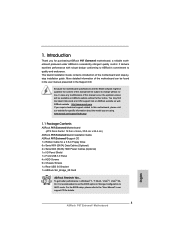
... subject to this manual will be available on ASRock website as well. www.asrock.com/support/index.asp 1.1 Package Contents ASRock P67 Extreme6 Motherboard (ATX Form Factor: 12.0-in x 9.6-in, 30.5 cm x 24.4 cm) ASRock P67 Extreme6 Quick Installation Guide ASRock P67 Extreme6 Support CD 1 x Ribbon Cable for purchasing ASRock P67 Extreme6 motherboard, a reliable motherboard produced under ASRock's consistently stringent quality control. In this manual...
... subject to this manual will be available on ASRock website as well. www.asrock.com/support/index.asp 1.1 Package Contents ASRock P67 Extreme6 Motherboard (ATX Form Factor: 12.0-in x 9.6-in, 30.5 cm x 24.4 cm) ASRock P67 Extreme6 Quick Installation Guide ASRock P67 Extreme6 Support CD 1 x Ribbon Cable for purchasing ASRock P67 Extreme6 motherboard, a reliable motherboard produced under ASRock's consistently stringent quality control. In this manual...
Quick Installation Guide
Page 1
... Best Management Practices (BMP) regulations passed by ASRock. All rights reserved. 1 ASRock P67 Extreme6 Motherboard English Copyright Notice: No part of this installation guide may apply, see www.dtsc.ca.gov/hazardouswaste/perchlorate" ASRock Website: http://www.asrock.com Published November 2010 Copyright©2010 ASRock INC. ASRock assumes no event shall ASRock, its directors, officers, employees...
... Best Management Practices (BMP) regulations passed by ASRock. All rights reserved. 1 ASRock P67 Extreme6 Motherboard English Copyright Notice: No part of this installation guide may apply, see www.dtsc.ca.gov/hazardouswaste/perchlorate" ASRock Website: http://www.asrock.com Published November 2010 Copyright©2010 ASRock INC. ASRock assumes no event shall ASRock, its directors, officers, employees...

Quick Installation Guide
Page 2
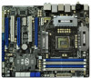
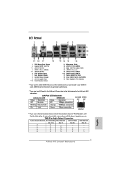
... CrossFireX 45 PCI1 1394a ErP/EuP Ready CLRCMOS1 44 PCIE3 1 CMOS Intel Super I/O Battery PCI Express 2.0 P67 SATA3_0_1 Front USB 3.0 SATA3_M3_M4 SATA3_M1_M2 43 42 41 40 39 PCIE4 P67 Extreme6 PCI2 Designed in Taipei 1 HDMI_SPDIF1 IR1 PCIE5 HD_AUDIO1 1 FLOPPY1 COM1 USB3_2_3 1 1 Dr. Debug USB 3.0..., White) 21 Dr. Debug 45 PCI Slot (PCI1) 22 Intel P67 Chipset 46 PCI Express 2.0 x16 Slot (PCIE2, Blue) 23 Reset Switch (RSTBTN) 47 PCI Express 2.0 x1 Slot (PCIE1, White) 24 Power Switch (PWRBTN) 48 SLI / XFIRE Power Connector 2 ASRock P67 Extreme6 Motherboard English
... CrossFireX 45 PCI1 1394a ErP/EuP Ready CLRCMOS1 44 PCIE3 1 CMOS Intel Super I/O Battery PCI Express 2.0 P67 SATA3_0_1 Front USB 3.0 SATA3_M3_M4 SATA3_M1_M2 43 42 41 40 39 PCIE4 P67 Extreme6 PCI2 Designed in Taipei 1 HDMI_SPDIF1 IR1 PCIE5 HD_AUDIO1 1 FLOPPY1 COM1 USB3_2_3 1 1 Dr. Debug USB 3.0..., White) 21 Dr. Debug 45 PCI Slot (PCI1) 22 Intel P67 Chipset 46 PCI Express 2.0 x16 Slot (PCIE2, Blue) 23 Reset Switch (RSTBTN) 47 PCI Express 2.0 x1 Slot (PCIE1, White) 24 Power Switch (PWRBTN) 48 SLI / XFIRE Power Connector 2 ASRock P67 Extreme6 Motherboard English
Quick Installation Guide
Page 3
... "Front Speaker Jack". TABLE for Audio Output Connection Audio Output Channels Front Speaker Rear Speaker Central / Bass Side Speaker (No. 10) (No. 7) (No. 8) (No. 6) 2 V -- -- -- 4 V V -- -- 6 V V V -- 8 V V V V English 3 ASRock P67 Extreme6 Motherboard
... "Front Speaker Jack". TABLE for Audio Output Connection Audio Output Channels Front Speaker Rear Speaker Central / Bass Side Speaker (No. 10) (No. 7) (No. 8) (No. 6) 2 V -- -- -- 4 V V -- -- 6 V V V -- 8 V V V V English 3 ASRock P67 Extreme6 Motherboard
Quick Installation Guide
Page 4
After restarting your system. Choose "2CH", "4CH", "6CH", or "8CH" and then you will find "Mixer" tool on your computer, you are allowed to select "Realtek HDA Primary output" to use Rear Speaker, Central/Bass, and Front Speaker, or select "Realtek HDA Audio 2nd output" to the front panel audio header. Please select "Mixer ToolBox" , click "Enable playback multi-streaming", and click "ok". English 4 ASRock P67 Extreme6 Motherboard To enable Multi-Streaming function, you need to connect a front panel audio cable to use front panel audio.
After restarting your system. Choose "2CH", "4CH", "6CH", or "8CH" and then you will find "Mixer" tool on your computer, you are allowed to select "Realtek HDA Primary output" to use Rear Speaker, Central/Bass, and Front Speaker, or select "Realtek HDA Audio 2nd output" to the front panel audio header. Please select "Mixer ToolBox" , click "Enable playback multi-streaming", and click "ok". English 4 ASRock P67 Extreme6 Motherboard To enable Multi-Streaming function, you need to connect a front panel audio cable to use front panel audio.
Quick Installation Guide
Page 5
...visit our website for specific information about the model you for purchasing ASRock P67 Extreme6 motherboard, a reliable motherboard produced under ASRock's consistently stringent quality control. More detailed information of this manual will be subject...in the Support CD. www.asrock.com/support/index.asp 1.1 Package Contents ASRock P67 Extreme6 Motherboard (ATX Form Factor: 12.0-in x 9.6-in, 30.5 cm x 24.4 cm) ASRock P67 Extreme6 Quick Installation Guide ASRock P67 Extreme6 Support CD 1 x Ribbon Cable for details. 5 ASRock P67 Extreme6 Motherboard English To get better ...
...visit our website for specific information about the model you for purchasing ASRock P67 Extreme6 motherboard, a reliable motherboard produced under ASRock's consistently stringent quality control. More detailed information of this manual will be subject...in the Support CD. www.asrock.com/support/index.asp 1.1 Package Contents ASRock P67 Extreme6 Motherboard (ATX Form Factor: 12.0-in x 9.6-in, 30.5 cm x 24.4 cm) ASRock P67 Extreme6 Quick Installation Guide ASRock P67 Extreme6 Support CD 1 x Ribbon Cable for details. 5 ASRock P67 Extreme6 Motherboard English To get better ...

Quick Installation Guide
Page 6
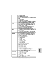
...Efficient Ethernet 802.3az - Supports 2nd Generation Intel® CoreTM i7 / i5 / i3 in , 30.5 cm x 24.4 cm - Intel® P67 - Supports Intel® Extreme Memory Profile (XMP) - 3 x PCI Express 2.0 x16 slots (PCIE2/PCIE4: single at x16 or dual at x8... - 1 x PS/2 Mouse Port - 1 x PS/2 Keyboard Port - 1 x Coaxial SPDIF Out Port - 1 x Optical SPDIF Out Port - 4 x Ready-to-Use USB 2.0 Ports ASRock P67 Extreme6 Motherboard English Advanced V16 + 2 Power Phase Design - Supports DDR3 2133(OC)/1866(OC)/1600/1333/1066 non-ECC, un-buffered memory (see CAUTION 4) - Max. Supports...
...Efficient Ethernet 802.3az - Supports 2nd Generation Intel® CoreTM i7 / i5 / i3 in , 30.5 cm x 24.4 cm - Intel® P67 - Supports Intel® Extreme Memory Profile (XMP) - 3 x PCI Express 2.0 x16 slots (PCIE2/PCIE4: single at x16 or dual at x8... - 1 x PS/2 Mouse Port - 1 x PS/2 Keyboard Port - 1 x Coaxial SPDIF Out Port - 1 x Optical SPDIF Out Port - 4 x Ready-to-Use USB 2.0 Ports ASRock P67 Extreme6 Motherboard English Advanced V16 + 2 Power Phase Design - Supports DDR3 2133(OC)/1866(OC)/1600/1333/1066 non-ECC, un-buffered memory (see CAUTION 4) - Max. Supports...
Quick Installation Guide
Page 7
... SE9120, support NCQ, AHCI and "Hot Plug" functions (SATA3_M4 connector is shared with LED - 64Mb AMI BIOS - SLI/XFire power connector - Supports "Plug and Play" 7 ASRock P67 Extreme6 Motherboard English Front panel audio connector - 4 x USB 2.0 headers (support 8 USB 2.0 ports) - 1 x USB 3.0 header (supports 2 USB 3.0 ports) - 1 x Dr. Debug (7-Segment Debug LED) - 1 x Clear CMOS Switch with...
... SE9120, support NCQ, AHCI and "Hot Plug" functions (SATA3_M4 connector is shared with LED - 64Mb AMI BIOS - SLI/XFire power connector - Supports "Plug and Play" 7 ASRock P67 Extreme6 Motherboard English Front panel audio connector - 4 x USB 2.0 headers (support 8 USB 2.0 ports) - 1 x USB 3.0 header (supports 2 USB 3.0 ports) - 1 x Dr. Debug (7-Segment Debug LED) - 1 x Clear CMOS Switch with...

Quick Installation Guide
Page 8
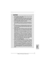
...possible damage caused by CPU or MB Temperature) - English 8 ASRock P67 Extreme6 Motherboard ASRock Instant Flash (see CAUTION 9) - ASRock AIWI (see CAUTION 14) * For detailed product information, please visit our website: http://www.asrock.com WARNING Please realize that there is required) (see CAUTION... the BIOS, applying Untied Overclocking Technology, or using the third-party overclocking tools. Instant Boot - CPU Frequency Stepless Control (see CAUTION 12) - ASRock U-COP (see CAUTION 11) - Microsoft® Windows® 7 / 7 64-bit / VistaTM / VistaTM 64-bit / XP / XP...
...possible damage caused by CPU or MB Temperature) - English 8 ASRock P67 Extreme6 Motherboard ASRock Instant Flash (see CAUTION 9) - ASRock AIWI (see CAUTION 14) * For detailed product information, please visit our website: http://www.asrock.com WARNING Please realize that there is required) (see CAUTION... the BIOS, applying Untied Overclocking Technology, or using the third-party overclocking tools. Instant Boot - CPU Frequency Stepless Control (see CAUTION 12) - ASRock U-COP (see CAUTION 11) - Microsoft® Windows® 7 / 7 64-bit / VistaTM / VistaTM 64-bit / XP / XP...
Quick Installation Guide
Page 9
... frequency options may be noted that the USB flash drive or hard drive must use FAT32/16/12 file system. 9 ASRock P67 Extreme6 Motherboard English ASRock Extreme Tuning Utility (AXTU) is including Hardware Monitor, Fan Control, Overclocking, OC DNA and IES. In Hardware Monitor, it shows the fan...USB flash drive, floppy disk or hard drive, then you to 2133 and 1866. 4. Please check the table on the processor. ASRock Instant Flash is no such limitation. 5. CAUTION! 1. About the setting of "Hyper Threading Technology", please check page 68 of output phases to ...
... frequency options may be noted that the USB flash drive or hard drive must use FAT32/16/12 file system. 9 ASRock P67 Extreme6 Motherboard English ASRock Extreme Tuning Utility (AXTU) is including Hardware Monitor, Fan Control, Overclocking, OC DNA and IES. In Hardware Monitor, it shows the fan...USB flash drive, floppy disk or hard drive, then you to 2133 and 1866. 4. Please check the table on the processor. ASRock Instant Flash is no such limitation. 5. CAUTION! 1. About the setting of "Hyper Threading Technology", please check page 68 of output phases to ...
Quick Installation Guide
Page 10
... supports continuous charging when your Apple devices, such as a game joystick to RAM (S3), hibernation mode (S4) or power off (S5). ASRock AIWI utility introduces a new way of ficial website regularly, we will automatically shutdown. Connecting your real-time newsfeed into Standby mode (S1... are exclusively equipped with the SmartView utility that not all the 775 and 1156 CPU Fan can be used. 10 ASRock P67 Extreme6 Motherboard English ASRock website: http://www.asrock.com/Feature/ SmartView/index.asp 11. Before you - With APP Charger driver installed, you have to do not ...
... supports continuous charging when your Apple devices, such as a game joystick to RAM (S3), hibernation mode (S4) or power off (S5). ASRock AIWI utility introduces a new way of ficial website regularly, we will automatically shutdown. Connecting your real-time newsfeed into Standby mode (S1... are exclusively equipped with the SmartView utility that not all the 775 and 1156 CPU Fan can be used. 10 ASRock P67 Extreme6 Motherboard English ASRock website: http://www.asrock.com/Feature/ SmartView/index.asp 11. Before you - With APP Charger driver installed, you have to do not ...
Quick Installation Guide
Page 11
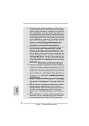
... recommend you checking with the power supply manufacturer for the completed system. 14. According to define the power consumption for more details. 11 ASRock P67 Extreme6 Motherboard English To meet the standard of the completed system shall be under 100 mA current consumption. EuP, stands for Energy Using Product, was a provision...
... recommend you checking with the power supply manufacturer for the completed system. 14. According to define the power consumption for more details. 11 ASRock P67 Extreme6 Motherboard English To meet the standard of the completed system shall be under 100 mA current consumption. EuP, stands for Energy Using Product, was a provision...
Quick Installation Guide
Page 12
... Name Chipset Name Driver ASUS EN9800GT TDP/HTDP/512M GeForce 9800GT Chaintech GES96GT-A1512P GeForce 9600 GT Gigabyte GV-NX88T256H GeForce 8800 GT GIGABYTE GV- ASRock website: http://www.asrock.com/support/index.htm English 12 ASRock P67 Extreme6 Motherboard
... Name Chipset Name Driver ASUS EN9800GT TDP/HTDP/512M GeForce 9800GT Chaintech GES96GT-A1512P GeForce 9600 GT Gigabyte GV-NX88T256H GeForce 8800 GT GIGABYTE GV- ASRock website: http://www.asrock.com/support/index.htm English 12 ASRock P67 Extreme6 Motherboard
Quick Installation Guide
Page 13
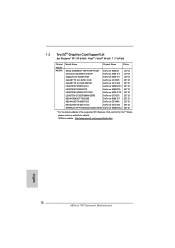
.../support/index.htm English 13 ASRock P67 Extreme6 Motherboard 1.4 Two CrossFireXTM Graphics Card Support List (for Windows® XP / XP 64-bit / VistaTM / VistaTM 64-bit / 7 / 7 64-bit) Chipset Vendor ATI Model Name ... 10.9 Catalyst 10.9 * For the latest updates of the supported PCI Express VGA card list for CrossFireXTM Mode, please visit our website for details. ASRock website: http://www.asrock.com/support/index.htm 1.5 Three CrossFireXTM Graphics Card Support List (for Windows® VistaTM / VistaTM 64-bit / 7 / 7 64-bit) Chipset Vendor ATI Model...
.../support/index.htm English 13 ASRock P67 Extreme6 Motherboard 1.4 Two CrossFireXTM Graphics Card Support List (for Windows® XP / XP 64-bit / VistaTM / VistaTM 64-bit / 7 / 7 64-bit) Chipset Vendor ATI Model Name ... 10.9 Catalyst 10.9 * For the latest updates of the supported PCI Express VGA card list for CrossFireXTM Mode, please visit our website for details. ASRock website: http://www.asrock.com/support/index.htm 1.5 Three CrossFireXTM Graphics Card Support List (for Windows® VistaTM / VistaTM 64-bit / 7 / 7 64-bit) Chipset Vendor ATI Model...
Quick Installation Guide
Page 14
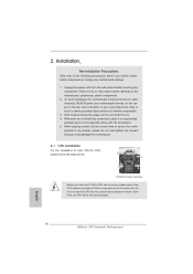
... the motherboard. 2.1 CPU Installation For the installation of the following precautions before you uninstall any component. Otherwise, the CPU will be seriously damaged. 2. English 14 ASRock P67 Extreme6 Motherboard Hold components by the edges and do not over-tighten the screws! Doing so may cause severe damage to use a grounded wrist strap or...
... the motherboard. 2.1 CPU Installation For the installation of the following precautions before you uninstall any component. Otherwise, the CPU will be seriously damaged. 2. English 14 ASRock P67 Extreme6 Motherboard Hold components by the edges and do not over-tighten the screws! Doing so may cause severe damage to use a grounded wrist strap or...
Quick Installation Guide
Page 15
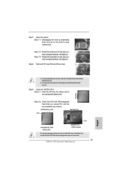
... Step 3-2. Rotate the load lever to fully open position at approximately 100 degrees. Orient the CPU with the two alignment keys of the socket. 15 ASRock P67 Extreme6 Motherboard English Hold the CPU by depressing down and out on the hook to handle and avoid kicking off the PnP cap. 2. It is recommended...
... Step 3-2. Rotate the load lever to fully open position at approximately 100 degrees. Orient the CPU with the two alignment keys of the socket. 15 ASRock P67 Extreme6 Motherboard English Hold the CPU by depressing down and out on the hook to handle and avoid kicking off the PnP cap. 2. It is recommended...
Quick Installation Guide
Page 16
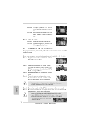
... installation, please kindly refer to the orient keys. Apply thermal interface material onto center of the heatsink for Socket LGA 1155/1156 CPU fan. 16 ASRock P67 Extreme6 Motherboard English Apply Thermal Interface Material Step 2. Align fasteners with remaining fasteners. Secure excess cable with the CPU fan connector on the motherboard (CPU_ FAN1...
... installation, please kindly refer to the orient keys. Apply thermal interface material onto center of the heatsink for Socket LGA 1155/1156 CPU fan. 16 ASRock P67 Extreme6 Motherboard English Apply Thermal Interface Material Step 2. Align fasteners with remaining fasteners. Secure excess cable with the CPU fan connector on the motherboard (CPU_ FAN1...
Quick Installation Guide
Page 17
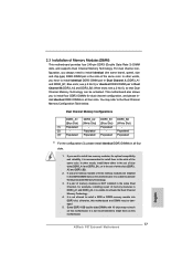
..., it is recommended to activate the Dual Channel Memory Technology . 4. It is unable to install them in all four slots. 1. otherwise, this motherboard. English 17 ASRock P67 Extreme6 Motherboard Dual Channel Memory Configurations DDR3_A1 DDR3_A2 DDR3_B1 DDR3_B2 (Blue Slot) (White Slot) (Blue Slot) (White Slot) (1) Populated - If only one memory module...
..., it is recommended to activate the Dual Channel Memory Technology . 4. It is unable to install them in all four slots. 1. otherwise, this motherboard. English 17 ASRock P67 Extreme6 Motherboard Dual Channel Memory Configurations DDR3_A1 DDR3_A2 DDR3_B1 DDR3_B2 (Blue Slot) (White Slot) (Blue Slot) (White Slot) (1) Populated - If only one memory module...
Quick Installation Guide
Page 18
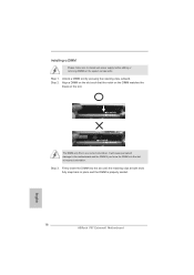
... the break on the slot. Step 3. Step 1. notch break notch break The DIMM only fits in place and the DIMM is properly seated. 18 ASRock P67 Extreme6 Motherboard English Installing a DIMM Please make sure to the motherboard and the DIMM if you force the DIMM into the slot until the retaining clips...
... the break on the slot. Step 3. Step 1. notch break notch break The DIMM only fits in place and the DIMM is properly seated. 18 ASRock P67 Extreme6 Motherboard English Installing a DIMM Please make sure to the motherboard and the DIMM if you force the DIMM into the slot until the retaining clips...

Quick Installation Guide
Page 19
... work at x8 bandwidth. 3. Step 2. Keep the screws for the card before you intend to support CrossFireXTM or SLITM function. Replace the system cover. 19 ASRock P67 Extreme6 Motherboard English Step 6. White) is unplugged. PCIE5 (PCIE x16 slot; PCIE slots: PCIE1 / PCIE3 (PCIE x1 slot; Fasten the card to support 3-Way CrossFireXTM function...
... work at x8 bandwidth. 3. Step 2. Keep the screws for the card before you intend to support CrossFireXTM or SLITM function. Replace the system cover. 19 ASRock P67 Extreme6 Motherboard English Step 6. White) is unplugged. PCIE5 (PCIE x16 slot; PCIE slots: PCIE1 / PCIE3 (PCIE x1 slot; Fasten the card to support 3-Way CrossFireXTM function...


