User Manual
Page 7
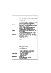
... - 4 x USB 2.0 headers (support 8 USB 2.0 ports) - 1 x USB 3.0 header (supports 2 USB 3.0 ports) - 1 x Dr. Debug (7-Segment Debug LED) - 1 x Clear CMOS Switch with LED - 1 x Power Switch with LED - 1 x Reset Switch with eSATA3 port) - 4 x Rear USB 3.0 ports by Etron EJ168A, support USB 1.0/ 2.0/3.0 up to 5Gb/s ... up to -Use USB 3.0 Ports - 2 x RJ-45 LAN Ports with LED (ACT/LINK LED and SPEED LED) - 1 x IEEE 1394 Port - 1 x Clear CMOS Switch with GUI support - Supports "Plug and Play" 7 HD Audio Jack: Side Speaker/Rear Speaker/Central/Bass/ Line in/Front Speaker/Microphone (see CAUTION 5) - 2...
... - 4 x USB 2.0 headers (support 8 USB 2.0 ports) - 1 x USB 3.0 header (supports 2 USB 3.0 ports) - 1 x Dr. Debug (7-Segment Debug LED) - 1 x Clear CMOS Switch with LED - 1 x Power Switch with LED - 1 x Reset Switch with eSATA3 port) - 4 x Rear USB 3.0 ports by Etron EJ168A, support USB 1.0/ 2.0/3.0 up to 5Gb/s ... up to -Use USB 3.0 Ports - 2 x RJ-45 LAN Ports with LED (ACT/LINK LED and SPEED LED) - 1 x IEEE 1394 Port - 1 x Clear CMOS Switch with GUI support - Supports "Plug and Play" 7 HD Audio Jack: Side Speaker/Rear Speaker/Central/Bass/ Line in/Front Speaker/Microphone (see CAUTION 5) - 2...

User Manual
Page 14
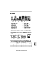
... 45 PCI1 1394a ErP/EuP Ready CLRCMOS1 44 PCIE3 1 CMOS Intel Super I/O Battery PCI Express 2.0 P67 SATA3_0_1 Front USB 3.0 SATA3_M3_M4 SATA3_M1_M2 43 42 41 40 39 PCIE4 P67 Extreme6 PCI2 Designed in Taipei 1 HDMI_SPDIF1 IR1 PCIE5 HD_AUDIO1 1 FLOPPY1...P67 Chipset 23 Reset Switch (RSTBTN) 24 Power Switch (PWRBTN) 25 Power LED Header (PLED1) 26 Chassis Speaker Header (SPEAKER 1, White) 27 System Panel Header (PANEL1, White) 28 Chassis Fan Connector (CHA_FAN1) 29 Chassis Fan Connector (CHA_FAN2) 30 USB 2.0 Header (USB12_13, Blue) 31 USB 2.0 Header (USB10_11, Blue) 32 Clear CMOS...
... 45 PCI1 1394a ErP/EuP Ready CLRCMOS1 44 PCIE3 1 CMOS Intel Super I/O Battery PCI Express 2.0 P67 SATA3_0_1 Front USB 3.0 SATA3_M3_M4 SATA3_M1_M2 43 42 41 40 39 PCIE4 P67 Extreme6 PCI2 Designed in Taipei 1 HDMI_SPDIF1 IR1 PCIE5 HD_AUDIO1 1 FLOPPY1...P67 Chipset 23 Reset Switch (RSTBTN) 24 Power Switch (PWRBTN) 25 Power LED Header (PLED1) 26 Chassis Speaker Header (SPEAKER 1, White) 27 System Panel Header (PANEL1, White) 28 Chassis Fan Connector (CHA_FAN1) 29 Chassis Fan Connector (CHA_FAN2) 30 USB 2.0 Header (USB12_13, Blue) 31 USB 2.0 Header (USB10_11, Blue) 32 Clear CMOS...

User Manual
Page 15
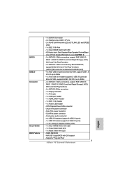
... 3.0 Ports (USB34) 13 IEEE 1394 Port (IEEE 1394) 14 eSATA3 Connector 15 USB 2.0 Ports (USB23) * 16 USB 3.0 Ports (USB12) 17 Optical SPDIF Out Port 18 Clear CMOS Switch (CLRCBTN) 19 PS/2 Keyboard Port (Purple) * If you use .
... 3.0 Ports (USB34) 13 IEEE 1394 Port (IEEE 1394) 14 eSATA3 Connector 15 USB 2.0 Ports (USB23) * 16 USB 3.0 Ports (USB12) 17 Optical SPDIF Out Port 18 Clear CMOS Switch (CLRCBTN) 19 PS/2 Keyboard Port (Purple) * If you use .

User Manual
Page 34
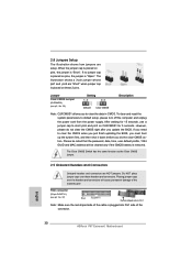
...red-striped side of the cable is placed on pins, the jumper is removed. If you need to clear the data in CMOS. The Clear CMOS Switch has the same function as the Clear CMOS jumper. 2.11 Onboard Headers and Connectors Onboard headers and connectors are setup. FDD connector (33-pin FLOPPY1)...side of the motherboard! Placing jumper caps over these 2 pins. After waiting for 5 seconds. However, please do not clear the CMOS right after you do the clear-CMOS action. If no jumper cap is placed on these headers and connectors. Do NOT place jumper caps over the headers ...
...red-striped side of the cable is placed on pins, the jumper is removed. If you need to clear the data in CMOS. The Clear CMOS Switch has the same function as the Clear CMOS jumper. 2.11 Onboard Headers and Connectors Onboard headers and connectors are setup. FDD connector (33-pin FLOPPY1)...side of the motherboard! Placing jumper caps over these 2 pins. After waiting for 5 seconds. However, please do not clear the CMOS right after you do the clear-CMOS action. If no jumper cap is placed on these headers and connectors. Do NOT place jumper caps over the headers ...

User Manual
Page 42
... Switch (PWRBTN) (see p.14 No. 23) RESET Reset Switch is a smart switch, allowing users to quickly clear the CMOS values. 42 2.12 Smart Switches The motherboard has three smart switches: power switch, reset switch and clear CMOS switch, allowing users to quickly turn on /off the system. Reset Switch (RSTBTN) (see p.14 No. 24...
... Switch (PWRBTN) (see p.14 No. 23) RESET Reset Switch is a smart switch, allowing users to quickly clear the CMOS values. 42 2.12 Smart Switches The motherboard has three smart switches: power switch, reset switch and clear CMOS switch, allowing users to quickly turn on /off the system. Reset Switch (RSTBTN) (see p.14 No. 24...

Quick Installation Guide
Page 2
...Slots 30 USB 2.0 Header (USB12_13, Blue) (Dual Channel: DDR3_A2, DDR3_B2, White) 31 USB 2.0 Header (USB10_11, Blue) 7 ATX Power Connector (ATXPWR1) 32 Clear CMOS Jumper (CLRCMOS1) 8 Front Panel IEEE 1394 Header 33 USB 2.0 Header (USB8_9, Blue) (FRONT_1394, White) 34 USB 2.0 Header (USB6_7, Blue) 9 Power Fan..., White) 21 Dr. Debug 45 PCI Slot (PCI1) 22 Intel P67 Chipset 46 PCI Express 2.0 x16 Slot (PCIE2, Blue) 23 Reset Switch (RSTBTN) 47 PCI Express 2.0 x1 Slot (PCIE1, White) 24 Power Switch (PWRBTN) 48 SLI / XFIRE Power Connector 2 ASRock P67 Extreme6 Motherboard English
...Slots 30 USB 2.0 Header (USB12_13, Blue) (Dual Channel: DDR3_A2, DDR3_B2, White) 31 USB 2.0 Header (USB10_11, Blue) 7 ATX Power Connector (ATXPWR1) 32 Clear CMOS Jumper (CLRCMOS1) 8 Front Panel IEEE 1394 Header 33 USB 2.0 Header (USB8_9, Blue) (FRONT_1394, White) 34 USB 2.0 Header (USB6_7, Blue) 9 Power Fan..., White) 21 Dr. Debug 45 PCI Slot (PCI1) 22 Intel P67 Chipset 46 PCI Express 2.0 x16 Slot (PCIE2, Blue) 23 Reset Switch (RSTBTN) 47 PCI Express 2.0 x1 Slot (PCIE1, White) 24 Power Switch (PWRBTN) 48 SLI / XFIRE Power Connector 2 ASRock P67 Extreme6 Motherboard English
Quick Installation Guide
Page 3
... Front Speaker Rear Speaker Central / Bass Side Speaker (No. 10) (No. 7) (No. 8) (No. 6) 2 V -- -- -- 4 V V -- -- 6 V V V -- 8 V V V V English 3 ASRock P67 Extreme6 Motherboard I/O Panel 1 2 3 45 69 7 10 8 11 19 18 17 16 1 PS/2 Mouse Port (Green) 2 Coaxial SPDIF Out Port * 3 LAN RJ-45 Port 4 USB 2.0 Ports (USB45... 1394) 14 eSATA3 Connector 15 USB 2.0 Ports (USB23) * 16 USB 3.0 Ports (USB12) 17 Optical SPDIF Out Port 18 Clear CMOS Switch (CLRCBTN) 19 PS/2 Keyboard Port (Purple) * If you want to install USB 3.0 device on this motherboard, we recommend to the ...
... Front Speaker Rear Speaker Central / Bass Side Speaker (No. 10) (No. 7) (No. 8) (No. 6) 2 V -- -- -- 4 V V -- -- 6 V V V -- 8 V V V V English 3 ASRock P67 Extreme6 Motherboard I/O Panel 1 2 3 45 69 7 10 8 11 19 18 17 16 1 PS/2 Mouse Port (Green) 2 Coaxial SPDIF Out Port * 3 LAN RJ-45 Port 4 USB 2.0 Ports (USB45... 1394) 14 eSATA3 Connector 15 USB 2.0 Ports (USB23) * 16 USB 3.0 Ports (USB12) 17 Optical SPDIF Out Port 18 Clear CMOS Switch (CLRCBTN) 19 PS/2 Keyboard Port (Purple) * If you want to install USB 3.0 device on this motherboard, we recommend to the ...
Quick Installation Guide
Page 7
... - 4 x Ready-to-Use USB 3.0 Ports - 2 x RJ-45 LAN Ports with LED (ACT/LINK LED and SPEED LED) - 1 x IEEE 1394 Port - 1 x Clear CMOS Switch with LED - 64Mb AMI BIOS - Supports "Plug and Play" 7 ASRock P67 Extreme6 Motherboard English Front panel audio connector - 4 x USB 2.0 headers (support 8 USB 2.0 ports) - 1 x USB 3.0 header (supports 2 USB 3.0 ports) - 1 x Dr. Debug (7-Segment Debug...
... - 4 x Ready-to-Use USB 3.0 Ports - 2 x RJ-45 LAN Ports with LED (ACT/LINK LED and SPEED LED) - 1 x IEEE 1394 Port - 1 x Clear CMOS Switch with LED - 64Mb AMI BIOS - Supports "Plug and Play" 7 ASRock P67 Extreme6 Motherboard English Front panel audio connector - 4 x USB 2.0 headers (support 8 USB 2.0 ports) - 1 x USB 3.0 header (supports 2 USB 3.0 ports) - 1 x Dr. Debug (7-Segment Debug...
Quick Installation Guide
Page 30
... user default profile, 1394 GUID and MAC address will cause permanent damage of the connector. English 30 ASRock P67 Extreme6 Motherboard If you need to clear the CMOS when you just finish updating the BIOS, you must boot up the system first, and then ... Onboard headers and connectors are setup. 2.8 Jumpers Setup The illustration shows how jumpers are NOT jumpers. However, please do the clear-CMOS action. Please be cleared only if the CMOS battery is placed on CLRCMOS1 for 5 seconds. Placing jumper caps over these 2 pins. FDD connector (33-pin FLOPPY1) ...
... user default profile, 1394 GUID and MAC address will cause permanent damage of the connector. English 30 ASRock P67 Extreme6 Motherboard If you need to clear the CMOS when you just finish updating the BIOS, you must boot up the system first, and then ... Onboard headers and connectors are setup. 2.8 Jumpers Setup The illustration shows how jumpers are NOT jumpers. However, please do the clear-CMOS action. Please be cleared only if the CMOS battery is placed on CLRCMOS1 for 5 seconds. Placing jumper caps over these 2 pins. FDD connector (33-pin FLOPPY1) ...

Quick Installation Guide
Page 38
... ASRock P67 Extreme6 Motherboard Power Switch (PWRBTN) (see p.2 No. 24) Power Switch is a smart switch, allowing users to quickly reset the system. 2.10 Smart Switches The motherboard has three smart switches: power switch, reset switch and clear CMOS switch, allowing users to quickly turn on /off the system. Reset Switch (RSTBTN) (see p.3 No. 18) clr CMOS Clear CMOS...
... ASRock P67 Extreme6 Motherboard Power Switch (PWRBTN) (see p.2 No. 24) Power Switch is a smart switch, allowing users to quickly reset the system. 2.10 Smart Switches The motherboard has three smart switches: power switch, reset switch and clear CMOS switch, allowing users to quickly turn on /off the system. Reset Switch (RSTBTN) (see p.3 No. 18) clr CMOS Clear CMOS...
Quick Installation Guide
Page 226
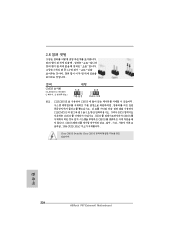
2.8 3 1-2 점퍼 CMOS 초기화 (CLRCMOS1, 3 2 32 세팅 CMOS 삭제 참고 : CLRCMOS1 CMOS 15 CLRCMOS1 의 핀 2 와 핀 3 을 5 BIOS CMOS BIOS CMOS CMOS CMOS 1394 GUID, MAC Clear CMOS Switch는 Clear CMOS 한 국 어 226 ASRock P67 Extreme6 Motherboard
2.8 3 1-2 점퍼 CMOS 초기화 (CLRCMOS1, 3 2 32 세팅 CMOS 삭제 참고 : CLRCMOS1 CMOS 15 CLRCMOS1 의 핀 2 와 핀 3 을 5 BIOS CMOS BIOS CMOS CMOS CMOS 1394 GUID, MAC Clear CMOS Switch는 Clear CMOS 한 국 어 226 ASRock P67 Extreme6 Motherboard

Quick Installation Guide
Page 301
2.8 3 1 和針腳 2 CMOS (CLRCMOS1, 3 2 頁第 32 項 ) 設定 默認設置 清除 CMOS 註: C L R C M O S1 C M O S 15 CLRCMOS1 的 pin2 及 pin3 短路 5 BIOS CMOS BIOS CMOS CMOS C M O S 1394 GUID 及 MAC Clear CMOS Clear CMOS 繁體中文 301 ASRock P67 Extreme6 Motherboard
2.8 3 1 和針腳 2 CMOS (CLRCMOS1, 3 2 頁第 32 項 ) 設定 默認設置 清除 CMOS 註: C L R C M O S1 C M O S 15 CLRCMOS1 的 pin2 及 pin3 短路 5 BIOS CMOS BIOS CMOS CMOS C M O S 1394 GUID 及 MAC Clear CMOS Clear CMOS 繁體中文 301 ASRock P67 Extreme6 Motherboard

