User Manual
Page 5
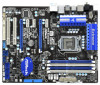
....5 cm x 24.4 cm) ASRock P55 Extreme4 Quick Installation Guide ASRock P55 Extreme4 Support CD 1 x 80-conductor Ultra ATA 66/100/133 IDE Ribbon Cable 1 x Ribbon Cable for purchasing ASRock P55 Extreme4 motherboard, a reliable motherboard produced under ASRock's consistently stringent quality control. Chapter 3 and 4 contain the configuration guide to BIOS setup and information of this manual occur, the updated version will be available...
....5 cm x 24.4 cm) ASRock P55 Extreme4 Quick Installation Guide ASRock P55 Extreme4 Support CD 1 x 80-conductor Ultra ATA 66/100/133 IDE Ribbon Cable 1 x Ribbon Cable for purchasing ASRock P55 Extreme4 motherboard, a reliable motherboard produced under ASRock's consistently stringent quality control. Chapter 3 and 4 contain the configuration guide to BIOS setup and information of this manual occur, the updated version will be available...
User Manual
Page 9
... modes. This motherboard supports Dual Channel Memory Technology. It is a user-friendly ASRock overclocking tool which allows you can update your BIOS only in Flash ROM. This convenient BIOS update tool allows you implement Dual Channel Memory Technology, make sure to access ASRock Instant Flash. With this motherboard supports both stereo and mono modes. OC DNA...
... modes. This motherboard supports Dual Channel Memory Technology. It is a user-friendly ASRock overclocking tool which allows you can update your BIOS only in Flash ROM. This convenient BIOS update tool allows you implement Dual Channel Memory Technology, make sure to access ASRock Instant Flash. With this motherboard supports both stereo and mono modes. OC DNA...
User Manual
Page 29
... jumpers are "Short" when jumper cap is placed on CLRCMOS1 for 15 seconds, use a jumper cap to clear the CMOS when you just finish updating the BIOS, you update the BIOS. When the jumper cap is placed on pins, the jumper is "Short". If no jumper cap is placed on pins, the jumper is...
... jumpers are "Short" when jumper cap is placed on CLRCMOS1 for 15 seconds, use a jumper cap to clear the CMOS when you just finish updating the BIOS, you update the BIOS. When the jumper cap is placed on pins, the jumper is "Short". If no jumper cap is placed on pins, the jumper is...
User Manual
Page 37
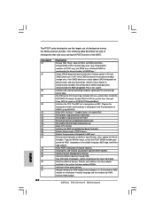
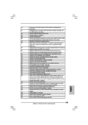
Initialize BIOS, POST, Runtime data area. Check CMOS diagnostic byte to ADM module for ADM module and uncompress it. Initialize CH-0 as mentioned in the system Initializes the interrupt controlling hardware (generally PIC) and interrupt vector table. Also, update the Kernel Variables. Early POST ... are based on KBC. Detects and initializes the video adapter installed in the system that may occur during the BIOS pre-boot process. Also initialize BIOS modules on default values and clear passwords. Do R/W test to "POSTINT1ChHandlerBlock." Traps the INT09h vector, so that...
Initialize BIOS, POST, Runtime data area. Check CMOS diagnostic byte to ADM module for ADM module and uncompress it. Initialize CH-0 as mentioned in the system Initializes the interrupt controlling hardware (generally PIC) and interrupt vector table. Also, update the Kernel Variables. Early POST ... are based on KBC. Detects and initializes the video adapter installed in the system that may occur during the BIOS pre-boot process. Also initialize BIOS modules on default values and clear passwords. Do R/W test to "POSTINT1ChHandlerBlock." Traps the INT09h vector, so that...
User Manual
Page 38
...chipset registers. 40 Detect different devices (Parallel ports, serial ports, and coprocessor in CPU, etc.) successfully installed in the system and update the BDA, EBDA, etc. 50 Programming the memory hole or any OEM specific information. 38 Initializes different devices through DIM. 39 ... memory test. Initializes the Microsoft IRQ Routing Table. A7 Displays the system configuration screen if enabled. Allocates memory for Extended BIOS Data Area from memory found in NVRam. 84 Log errors encountered during POST. 85 Display errors to limit memory test....
...chipset registers. 40 Detect different devices (Parallel ports, serial ports, and coprocessor in CPU, etc.) successfully installed in the system and update the BDA, EBDA, etc. 50 Programming the memory hole or any OEM specific information. 38 Initializes different devices through DIM. 39 ... memory test. Initializes the Microsoft IRQ Routing Table. A7 Displays the system configuration screen if enabled. Allocates memory for Extended BIOS Data Area from memory found in NVRam. 84 Log errors encountered during POST. 85 Display errors to limit memory test....
User Manual
Page 49
... the system off and then back on the menu bar, and then press to get into the sub screen. 49 Because the BIOS software is constantly being updated, the following selections: Main To set up the system time/date information OC Tweaker To set up overclocking features Advanced To set... up the advanced BIOS features H/W Monitor To display current hardware status Boot To set up the default system device to locate and load the...
... the system off and then back on the menu bar, and then press to get into the sub screen. 49 Because the BIOS software is constantly being updated, the following selections: Main To set up the system time/date information OC Tweaker To set up overclocking features Advanced To set... up the advanced BIOS features H/W Monitor To display current hardware status Boot To set up the default system device to locate and load the...
User Manual
Page 50
... H/W Monitor Boot Security Exit System Overview System Time System Date [14:00:09] [Fri 06/25/2010] BIOS Version : P55 Extreme4 P1.00 Processor Type : Intel (R) Core (TM) i7 CPU 880 @ 3.07GHz (64bit) Processor Speed : 3066MHz Microcode Update : 106E5/3 Cache Size : 8192KB Total Memory DDR3_A2 DDR3_A1 DDR3_B2 DDR3_B1 : 2048MB Single-Channel Memory Mode : None... for the function description of each navigation key. 3.1.2Navigation Keys Please check the following table for all the settings To save changes and exit the BIOS SETUP UTILITY To jump to specify the system time.
... H/W Monitor Boot Security Exit System Overview System Time System Date [14:00:09] [Fri 06/25/2010] BIOS Version : P55 Extreme4 P1.00 Processor Type : Intel (R) Core (TM) i7 CPU 880 @ 3.07GHz (64bit) Processor Speed : 3066MHz Microcode Update : 106E5/3 Cache Size : 8192KB Total Memory DDR3_A2 DDR3_A1 DDR3_B2 DDR3_B1 : 2048MB Single-Channel Memory Mode : None... for the function description of each navigation key. 3.1.2Navigation Keys Please check the following table for all the settings To save changes and exit the BIOS SETUP UTILITY To jump to specify the system time.
User Manual
Page 56
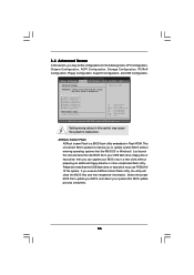
... USB Configuration. CPU Configuration Chipset Configuration ACPI Configuration Storage Configuration PCIPnP Configuration Floppy Configuration SuperIO Configuration USB Configuration BIOS Update Utility ASRock Instant Flash Select Screen Select Item Enter Go to update your BIOS, and reboot your BIOS only in this section may set the configurations for CPU WARNING : Setting wrong values in Flash ROM. If...
... USB Configuration. CPU Configuration Chipset Configuration ACPI Configuration Storage Configuration PCIPnP Configuration Floppy Configuration SuperIO Configuration USB Configuration BIOS Update Utility ASRock Instant Flash Select Screen Select Item Enter Go to update your BIOS, and reboot your BIOS only in this section may set the configurations for CPU WARNING : Setting wrong values in Flash ROM. If...

Quick Installation Guide
Page 4
... the BIOS software might be updated, the content of this manual occur, the updated version will be found in the user manual presented in Floppy Drive 4 x Serial ATA (SATA) Data Cables (Optional) 2 x Serial ATA (SATA) HDD Power Cables (Optional) 1 x I/O Panel Shield 1 x ASRock SLI_Bridge_2S Card 1 x Front USB 3.0 Panel 6 x Screws 4 ASRock P55 Extreme4 Motherboard English ASRock website http://www.asrock.com...
... the BIOS software might be updated, the content of this manual occur, the updated version will be found in the user manual presented in Floppy Drive 4 x Serial ATA (SATA) Data Cables (Optional) 2 x Serial ATA (SATA) HDD Power Cables (Optional) 1 x I/O Panel Shield 1 x ASRock SLI_Bridge_2S Card 1 x Front USB 3.0 Panel 6 x Screws 4 ASRock P55 Extreme4 Motherboard English ASRock website http://www.asrock.com...
Quick Installation Guide
Page 8
...®. With OC DNA, you can save your overclocking record under Windows® 7 / VistaTM / XP. This convenient BIOS update tool allows you to update system BIOS without sacrificing computing performance. It is no such limitation. 5. Please be less than 4GB for the reservation for the user... your OC settings as a profile and share with 8 ASRock P55 Extreme4 Motherboard English Before you what it is capable of "User Manual" in a few clicks without preparing an additional floppy diskette or other words, it is a BIOS flash utility embedded in Flash ROM. Due to read "...
...®. With OC DNA, you can save your overclocking record under Windows® 7 / VistaTM / XP. This convenient BIOS update tool allows you to update system BIOS without sacrificing computing performance. It is no such limitation. 5. Please be less than 4GB for the reservation for the user... your OC settings as a profile and share with 8 ASRock P55 Extreme4 Motherboard English Before you what it is capable of "User Manual" in a few clicks without preparing an additional floppy diskette or other words, it is a BIOS flash utility embedded in Flash ROM. Due to read "...
Quick Installation Guide
Page 24
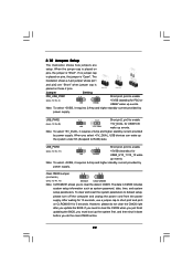
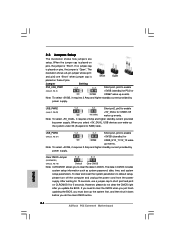
USB_PWR3 Short pin2, pin3 to enable (see p.2, No.49) +5V_DUAL for PS/2 or USB67 wake up events. English 24 ASRock P55 Extreme4 Motherboard The illustration shows a 3-pin jumper whose pin1 and pin2 are setup. Note: To select +5VSB, it requires 2 Amp and higher standby current ...includes system setup information such as system password, date, time, and system setup parameters. If you need to clear the CMOS when you just finish updating the BIOS, you to enable (see p.2, No. 15) Default Clear CMOS Note: CLRCMOS1 allows you must boot up events. If no jumper cap is ...
USB_PWR3 Short pin2, pin3 to enable (see p.2, No.49) +5V_DUAL for PS/2 or USB67 wake up events. English 24 ASRock P55 Extreme4 Motherboard The illustration shows a 3-pin jumper whose pin1 and pin2 are setup. Note: To select +5VSB, it requires 2 Amp and higher standby current ...includes system setup information such as system password, date, time, and system setup parameters. If you need to clear the CMOS when you just finish updating the BIOS, you to enable (see p.2, No. 15) Default Clear CMOS Note: CLRCMOS1 allows you must boot up events. If no jumper cap is ...
Quick Installation Guide
Page 32
... power is OK and CMOS checksum is bad, update CMOS with power-on POST entry and GPNV area. Testing and initialization of PS/2 mouse. Initialize CH-0 as mentioned in the Kernel Variable "wCMOSFlags." Initializes different devices. Allocate memory for ADM. ASRock P55 Extreme4 Motherboard English Initialize BIOS, POST, Runtime data area. Initialize language and font...
... power is OK and CMOS checksum is bad, update CMOS with power-on POST entry and GPNV area. Testing and initialization of PS/2 mouse. Initialize CH-0 as mentioned in the Kernel Variable "wCMOSFlags." Initializes different devices. Allocate memory for ADM. ASRock P55 Extreme4 Motherboard English Initialize BIOS, POST, Runtime data area. Initialize language and font...
Quick Installation Guide
Page 33
...language module. AB Prepare BBS for DEL or ESC keys to OS. English 33 ASRock P55 Extreme4 Motherboard Display total memory in the system. 3C Mid POST initialization of the MTRR's. ... initialization of runtime image preparation for IPL detection. 78 Initializes IPL devices controlled by BIOS and option ROMs. 7A Initializes remaining option ROMs. 7C Generate and write contents of... ports, serial ports, and coprocessor in CPU, etc.) successfully installed in the system and update the BDA, EBDA, etc. 50 Programming the memory hole or any OEM specific information. ...
...language module. AB Prepare BBS for DEL or ESC keys to OS. English 33 ASRock P55 Extreme4 Motherboard Display total memory in the system. 3C Mid POST initialization of the MTRR's. ... initialization of runtime image preparation for IPL detection. 78 Initializes IPL devices controlled by BIOS and option ROMs. 7A Initializes remaining option ROMs. 7C Generate and write contents of... ports, serial ports, and coprocessor in CPU, etc.) successfully installed in the system and update the BDA, EBDA, etc. 50 Programming the memory hole or any OEM specific information. ...


