User Manual
Page 3
... Support List 11 1.5 Motherboard Layout 12 1.6 I/O Panel 13 2 Installation 15 2.1 Screw Holes 15 2.2 Pre-installation Precautions 15 2.3 CPU Installation 16 2.4 Installation of Heatsink and CPU fan 18 2.5 Installation of Memory Modules (DIMM 19 2.6 Expansion Slots (PCI and PCI Express Slots 21 2.7 SLITM and Quad SLITM Operation Guide 22 2.8 CrossFireXTM and Quad...
... Support List 11 1.5 Motherboard Layout 12 1.6 I/O Panel 13 2 Installation 15 2.1 Screw Holes 15 2.2 Pre-installation Precautions 15 2.3 CPU Installation 16 2.4 Installation of Heatsink and CPU fan 18 2.5 Installation of Memory Modules (DIMM 19 2.6 Expansion Slots (PCI and PCI Express Slots 21 2.7 SLITM and Quad SLITM Operation Guide 22 2.8 CrossFireXTM and Quad...
User Manual
Page 7
....0 ports by Marvell SE9128, support hardware RAID (RAID 0 and RAID 1), NCQ, AHCI and "Hot Plug" functions (SATA3_2 connector is shared with LED - CPU/Chassis/Power FAN connector - 24 pin ATX power connector - 8 pin 12V power connector - Front panel audio connector - 3 x USB 2.0 headers (support 6 USB 2.0 ports) (see CAUTION 6) - 2 x SATA3 6.0Gb/s connectors by...
....0 ports by Marvell SE9128, support hardware RAID (RAID 0 and RAID 1), NCQ, AHCI and "Hot Plug" functions (SATA3_2 connector is shared with LED - CPU/Chassis/Power FAN connector - 24 pin ATX power connector - 8 pin 12V power connector - Front panel audio connector - 3 x USB 2.0 headers (support 6 USB 2.0 ports) (see CAUTION 6) - 2 x SATA3 6.0Gb/s connectors by...

User Manual
Page 8
...Feature - Chassis Temperature Sensing - CPU/Chassis Fan Multi-Speed Control - - It should be done at your system. ASRock OC Tuner (see CAUTION 10) - ASRock Instant Flash (see CAUTION 8) - CPU Frequency Stepless Control (see CAUTION 11) - CPU Quiet Fan - Overclocking may affect your system stability, ...or even cause damage to the components and devices of your own risk and expense. CPU, VCCM, SB, VTT, PCH PLL Voltage Multi-adjustment - ASRock OC DNA (see CAUTION 12) - ...
...Feature - Chassis Temperature Sensing - CPU/Chassis Fan Multi-Speed Control - - It should be done at your system. ASRock OC Tuner (see CAUTION 10) - ASRock Instant Flash (see CAUTION 8) - CPU Frequency Stepless Control (see CAUTION 11) - CPU Quiet Fan - Overclocking may affect your system stability, ...or even cause damage to the components and devices of your own risk and expense. CPU, VCCM, SB, VTT, PCH PLL Voltage Multi-adjustment - ASRock OC DNA (see CAUTION 12) - ...

User Manual
Page 10
... Union to perform over-clocking. According to EuP, the total AC power of overclocking settings. Please be noticed that not all the 775 CPU Fan can only be under 100 mA current consumption. Please be noticed that the OC profile can be used. 15. To meet the standard of ... when you to get the same OC settings as a profile and share with others. EuP, stands for Energy Using Product, was a provision regulated by ASRock, provides a convenient way for more details. 10 11. OC DNA literally tells you checking with the power supply manufacturer for the user to adopt two...
... Union to perform over-clocking. According to EuP, the total AC power of overclocking settings. Please be noticed that not all the 775 CPU Fan can only be under 100 mA current consumption. Please be noticed that the OC profile can be used. 15. To meet the standard of ... when you to get the same OC settings as a profile and share with others. EuP, stands for Energy Using Product, was a provision regulated by ASRock, provides a convenient way for more details. 10 11. OC DNA literally tells you checking with the power supply manufacturer for the user to adopt two...
User Manual
Page 12
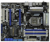
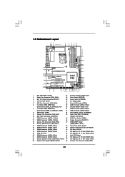
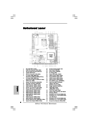
... 42 41 40 39 38 PCIE1 LAN PHY PCIE2 CHA_FAN3 CHA_FAN2 IDE1 EuP Ready SATA3 6Gb/s SATAII_5_6 SATAII_3_4 SATAII_1_2 PCIE3 Super I/O P55 Deluxe3 Intel P55 PCIE4 PCI Express 2.0 1394a AUDIO CODEC HD_AUDIO1 1 CD1 HDMI_SPDIF1 1 FLOPPY1 PCI1 RoHS PCI2 COM1 1 CMOS Battery FRONT_1394 USB8_9 USB4_5... Connector (SATA3_1, White) 35 COM Port Header (COM1) 12 SATA3 Connector (SATA3_2, White) 36 Floppy Connector (FLOPPY1) 13 Chassis Fan Connector (CHA_FAN2) 37 HDMI_SPDIF Header 14 Primary IDE Connector (IDE1, Blue) (HDMI_SPDIF1, White) 15 SATAII Connector (SATAII_2, Blue ) 38...
... 42 41 40 39 38 PCIE1 LAN PHY PCIE2 CHA_FAN3 CHA_FAN2 IDE1 EuP Ready SATA3 6Gb/s SATAII_5_6 SATAII_3_4 SATAII_1_2 PCIE3 Super I/O P55 Deluxe3 Intel P55 PCIE4 PCI Express 2.0 1394a AUDIO CODEC HD_AUDIO1 1 CD1 HDMI_SPDIF1 1 FLOPPY1 PCI1 RoHS PCI2 COM1 1 CMOS Battery FRONT_1394 USB8_9 USB4_5... Connector (SATA3_1, White) 35 COM Port Header (COM1) 12 SATA3 Connector (SATA3_2, White) 36 Floppy Connector (FLOPPY1) 13 Chassis Fan Connector (CHA_FAN2) 37 HDMI_SPDIF Header 14 Primary IDE Connector (IDE1, Blue) (HDMI_SPDIF1, White) 15 SATAII Connector (SATAII_2, Blue ) 38...
User Manual
Page 18
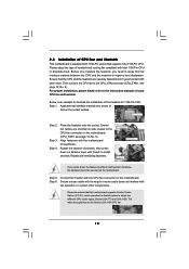
...Cooler Option (C.C.O.), which provides the flexible option to dissipate heat. Repeat with the motherboard throughholes. Connect fan header with fan operation or contact other . 2.4 Installation of CPU Fan and Heatsink This motherboard is an example to illustrate the installation of the heatsink for Socket LGA ...and the heatsink to install and lock. For proper installation, please kindly refer to the CPU fan connector on fastener caps with each other components. Ensure fan cables are for 1156-Pin CPU. The white throughholes are oriented on side closest to the instruction...
...Cooler Option (C.C.O.), which provides the flexible option to dissipate heat. Repeat with the motherboard throughholes. Connect fan header with fan operation or contact other . 2.4 Installation of CPU Fan and Heatsink This motherboard is an example to illustrate the installation of the heatsink for Socket LGA ...and the heatsink to install and lock. For proper installation, please kindly refer to the CPU fan connector on fastener caps with each other components. Ensure fan cables are for 1156-Pin CPU. The white throughholes are oriented on side closest to the instruction...

User Manual
Page 21
... two slots will work at x8 bandwidth. 3. Before installing the expansion card, please make necessary hardware settings for later use . Please connect a chassis fan to motherboard chassis fan connector (CHA_FAN1, CHA_FAN2 or CHA_FAN3) when using multiple graphics cards for PCI Express cards with x1 lane width cards, such as Gigabit LAN card...
... two slots will work at x8 bandwidth. 3. Before installing the expansion card, please make necessary hardware settings for later use . Please connect a chassis fan to motherboard chassis fan connector (CHA_FAN1, CHA_FAN2 or CHA_FAN3) when using multiple graphics cards for PCI Express cards with x1 lane width cards, such as Gigabit LAN card...

User Manual
Page 34
...motherboard, please connect it to this motherboard provides 4-Pin CPU fan (Quiet Fan) support, the 3-Pin CPU fan still can work successfully even without the fan speed control function. Please connect the fan cables to the fan connectors and match the black wire to the ground pin.... CHA_FAN_SPEED (3-pin CHA_FAN3) (see p.12 No. 46) (3-pin PWR_FAN1) (see p.12 No. 2) GND CHA_FAN3_PWR CHA_FAN_SPEED PWR_FAN_SPEED +12V GND CPU Fan Connector (4-pin CPU_FAN1) (see p.12 No. 9) GND +12V CHA_FAN_SPEED FAN_SPEED_CONTROL Please connect the chassis speaker to Pin 1-3. The LED is on this...
...motherboard, please connect it to this motherboard provides 4-Pin CPU fan (Quiet Fan) support, the 3-Pin CPU fan still can work successfully even without the fan speed control function. Please connect the fan cables to the fan connectors and match the black wire to the ground pin.... CHA_FAN_SPEED (3-pin CHA_FAN3) (see p.12 No. 46) (3-pin PWR_FAN1) (see p.12 No. 2) GND CHA_FAN3_PWR CHA_FAN_SPEED PWR_FAN_SPEED +12V GND CPU Fan Connector (4-pin CPU_FAN1) (see p.12 No. 9) GND +12V CHA_FAN_SPEED FAN_SPEED_CONTROL Please connect the chassis speaker to Pin 1-3. The LED is on this...

User Manual
Page 41
... the HDMI_SPDIF header (HDMI_SPDIF1, white, see page 12, No. 37) on HDMI VGA card, please refer to the user manual of HDMI_SPDIF cable to the fan connector of PCI Express VGA card. Connect the black end (A) of HDMI VGA card vendor. For the pin definition of HDMI_SPDIF connectors on the motherboard...
... the HDMI_SPDIF header (HDMI_SPDIF1, white, see page 12, No. 37) on HDMI VGA card, please refer to the user manual of HDMI_SPDIF cable to the fan connector of PCI Express VGA card. Connect the black end (A) of HDMI VGA card vendor. For the pin definition of HDMI_SPDIF connectors on the motherboard...

User Manual
Page 69
... mode]. The default is value [Full On]. The default is value [Enabled]. Case Open Feature This allows you to set the chassis fan 2 speed. Configuration options: [Full On] and [Manual mode]. Use this section, it allows you to keep or clear the record of... the CPU temperature, motherboard temperature, CPU fan speed, chassis fan speed, and the critical voltage. BIOS SETUP UTILITY Main OC Tweaker Advanced H/W Monitor Boot Security Exit Hardware Health Event Monitoring CPU Temperature...
... mode]. The default is value [Full On]. The default is value [Enabled]. Case Open Feature This allows you to set the chassis fan 2 speed. Configuration options: [Full On] and [Manual mode]. Use this section, it allows you to keep or clear the record of... the CPU temperature, motherboard temperature, CPU fan speed, chassis fan speed, and the critical voltage. BIOS SETUP UTILITY Main OC Tweaker Advanced H/W Monitor Boot Security Exit Hardware Health Event Monitoring CPU Temperature...
Quick Installation Guide
Page 2
...SATA3 Connector (SATA3_1, White) 35 COM Port Header (COM1) 12 SATA3 Connector (SATA3_2, White) 36 Floppy Connector (FLOPPY1) 13 Chassis Fan Connector (CHA_FAN2) 37 HDMI_SPDIF Header 14 Primary IDE Connector (IDE1, Blue) (HDMI_SPDIF1, White) 15 SATAII Connector (SATAII_2, Blue ) 38... Blue ) 43 Intel P55 Chipset 21 SATAII Connector (SATAII_6, Blue ) 44 PCI Express 2.0 x16 Slot (PCIE2, Blue) 22 Chassis Speaker Header (SPEAKER 1, White) 45 PCI Express 2.0 x1 Slot (PCIE1, White) 23 System Panel Header (PANEL1, White) 46 Chassis Fan Connector (CHA_FAN2) 2 ASRock P55 Deluxe3 Motherboard
...SATA3 Connector (SATA3_1, White) 35 COM Port Header (COM1) 12 SATA3 Connector (SATA3_2, White) 36 Floppy Connector (FLOPPY1) 13 Chassis Fan Connector (CHA_FAN2) 37 HDMI_SPDIF Header 14 Primary IDE Connector (IDE1, Blue) (HDMI_SPDIF1, White) 15 SATAII Connector (SATAII_2, Blue ) 38... Blue ) 43 Intel P55 Chipset 21 SATAII Connector (SATAII_6, Blue ) 44 PCI Express 2.0 x16 Slot (PCIE2, Blue) 22 Chassis Speaker Header (SPEAKER 1, White) 45 PCI Express 2.0 x1 Slot (PCIE1, White) 23 System Panel Header (PANEL1, White) 46 Chassis Fan Connector (CHA_FAN2) 2 ASRock P55 Deluxe3 Motherboard
Quick Installation Guide
Page 7
...HDMI_SPDIF header - 1 x IEEE 1394 header - 1 x TPM header - 1 x Chassis Intrusion header - 1 x Power LED header - AMI Legal BIOS - SMBIOS 2.3.1 Support 7 ASRock P55 Deluxe3 Motherboard English CD in /Front Speaker/Microphone (see CAUTION 7) - 1 x Dr. Debug (7-Segment Debug LED) - 1 x Clear CMOS Switch with LED - 1 x Power Switch ...Switch with LED - Supports "Plug and Play" - ACPI 1.1 Compliance Wake Up Events - Supports jumperfree - CPU/Chassis/Power FAN connector - 24 pin ATX power connector - 8 pin 12V power connector - SATA3 USB3.0 Connector Smart Switch BIOS Feature - 1...
...HDMI_SPDIF header - 1 x IEEE 1394 header - 1 x TPM header - 1 x Chassis Intrusion header - 1 x Power LED header - AMI Legal BIOS - SMBIOS 2.3.1 Support 7 ASRock P55 Deluxe3 Motherboard English CD in /Front Speaker/Microphone (see CAUTION 7) - 1 x Dr. Debug (7-Segment Debug LED) - 1 x Clear CMOS Switch with LED - 1 x Power Switch ...Switch with LED - Supports "Plug and Play" - ACPI 1.1 Compliance Wake Up Events - Supports jumperfree - CPU/Chassis/Power FAN connector - 24 pin ATX power connector - 8 pin 12V power connector - SATA3 USB3.0 Connector Smart Switch BIOS Feature - 1...

Quick Installation Guide
Page 8
... Fan - CPU/Chassis Fan Multi-Speed Control - FCC, CE, WHQL - O. Intelligent Energy Saver (see CAUTION 10) - ASRock Instant Flash (see CAUTION 9) - It should be done at your system. We are not responsible for possible damage caused by overclocking. English 8 ASRock P55 Deluxe3 ...Motherboard Combo Cooler Option (C.C.O.) (see CAUTION 15) * For detailed product information, please visit our website: http://www.asrock.com WARNING Please realize that there is required) (see ...
... Fan - CPU/Chassis Fan Multi-Speed Control - FCC, CE, WHQL - O. Intelligent Energy Saver (see CAUTION 10) - ASRock Instant Flash (see CAUTION 9) - It should be done at your system. We are not responsible for possible damage caused by overclocking. English 8 ASRock P55 Deluxe3 ...Motherboard Combo Cooler Option (C.C.O.) (see CAUTION 15) * For detailed product information, please visit our website: http://www.asrock.com WARNING Please realize that there is required) (see ...

Quick Installation Guide
Page 10
...the same motherboard. 12. With OC DNA, you checking with the power supply manufacturer for more details. 10 ASRock P55 Deluxe3 Motherboard English Please be noticed that not all the 775 CPU Fan can only be under 100 mA current consumption. Please be noticed that the OC profile can be used. 15.... LGA 1156. Frequencies other than 50% under 1.00W in off mode condition. EuP, stands for Energy Using Product, was a provision regulated by ASRock, provides a convenient way for the completed system. Combo Cooler Option (C.C.O.) provides the flexible option to perform over-clocking.
...the same motherboard. 12. With OC DNA, you checking with the power supply manufacturer for more details. 10 ASRock P55 Deluxe3 Motherboard English Please be noticed that not all the 775 CPU Fan can only be under 100 mA current consumption. Please be noticed that the OC profile can be used. 15.... LGA 1156. Frequencies other than 50% under 1.00W in off mode condition. EuP, stands for Energy Using Product, was a provision regulated by ASRock, provides a convenient way for the completed system. Combo Cooler Option (C.C.O.) provides the flexible option to perform over-clocking.

Quick Installation Guide
Page 14
... this motherboard supports Combo Cooler Option (C.C.O.), which provides the flexible option to illustrate the installation of the heatsink for Socket LGA 1156 CPU fan. 14 ASRock P55 Deluxe3 Motherboard English Step 1. Ensure fan cables are for 1156-Pin CPU. Repeat with the motherboard throughholes. Step 6. Step 4. Step 4-3. Apply thermal interface material onto center of your...
... this motherboard supports Combo Cooler Option (C.C.O.), which provides the flexible option to illustrate the installation of the heatsink for Socket LGA 1156 CPU fan. 14 ASRock P55 Deluxe3 Motherboard English Step 1. Ensure fan cables are for 1156-Pin CPU. Repeat with the motherboard throughholes. Step 6. Step 4. Step 4-3. Apply thermal interface material onto center of your...

Quick Installation Guide
Page 17
...motherboard is unplugged. PCIE slots: PCIE1 / PCIE3 (PCIE x1 slot; Blue) is recommended to motherboard chassis fan connector (CHA_FAN1, CHA_FAN2 or CHA_FAN3) when using multiple graphics cards for PCI Express cards with x1 lane width... cards, such as Gigabit LAN card, SATA2 card, etc. Please connect a chassis fan to install a PCI Express x16 graphics card on the slot. Fasten the card to install expansion cards...slots on PCIE2 and PCIE4 slots. Replace the system cover. 17 ASRock P55 Deluxe3 Motherboard English White) is completely seated on PCIE2 slot. 2.
...motherboard is unplugged. PCIE slots: PCIE1 / PCIE3 (PCIE x1 slot; Blue) is recommended to motherboard chassis fan connector (CHA_FAN1, CHA_FAN2 or CHA_FAN3) when using multiple graphics cards for PCI Express cards with x1 lane width... cards, such as Gigabit LAN card, SATA2 card, etc. Please connect a chassis fan to install a PCI Express x16 graphics card on the slot. Fasten the card to install expansion cards...slots on PCIE2 and PCIE4 slots. Replace the system cover. 17 ASRock P55 Deluxe3 Motherboard English White) is completely seated on PCIE2 slot. 2.

Quick Installation Guide
Page 28
... Speaker Header (4-pin SPEAKER 1) (see p.2 No. 22) Power LED Header (3-pin PLED1) (see p.2 No. 28) Chassis and Power Fan Connectors (4-pin CHA_FAN1) (see p.2 No. 9) (3-pin CHA_FAN2) (see p.2 No. 13) Please connect the chassis speaker to Pin 1-3....Fan Connector (4-pin CPU_FAN1) (see p.2, No. 10) 12 24 Please connect an ATX power supply to this connector and match the black wire to indicate system power status. Pin 1-3 Connected 3-Pin Fan Installation ATX Power Connector (24-pin ATXPWR1) (see p.2 No. 5) Please connect a CPU fan cable to this connector. 28 1 13 ASRock P55 Deluxe3...
... Speaker Header (4-pin SPEAKER 1) (see p.2 No. 22) Power LED Header (3-pin PLED1) (see p.2 No. 28) Chassis and Power Fan Connectors (4-pin CHA_FAN1) (see p.2 No. 9) (3-pin CHA_FAN2) (see p.2 No. 13) Please connect the chassis speaker to Pin 1-3....Fan Connector (4-pin CPU_FAN1) (see p.2, No. 10) 12 24 Please connect an ATX power supply to this connector and match the black wire to indicate system power status. Pin 1-3 Connected 3-Pin Fan Installation ATX Power Connector (24-pin ATXPWR1) (see p.2 No. 5) Please connect a CPU fan cable to this connector. 28 1 13 ASRock P55 Deluxe3...


