Intel Rapid Storage Guide
Page 13
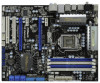
.... Use the Floppy Configuration Utility to create a floppy disk with a screen asking you see a message in the status line that says, Please insert the disk labeled Manufacturer-supplied hardware support disk into Drive A:, insert ;a floppy disk containing the following steps to install a third party SCSI or RAID driver. 7. Press Enter to load support for mass storage device(s). 2. When you to confirm your controller from the list of Windows XP* setup (during operating system setup: 1. Select the volume size...
.... Use the Floppy Configuration Utility to create a floppy disk with a screen asking you see a message in the status line that says, Please insert the disk labeled Manufacturer-supplied hardware support disk into Drive A:, insert ;a floppy disk containing the following steps to install a third party SCSI or RAID driver. 7. Press Enter to load support for mass storage device(s). 2. When you to confirm your controller from the list of Windows XP* setup (during operating system setup: 1. Select the volume size...
RAID Installation Guide
Page 7
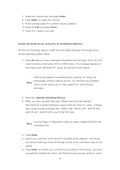
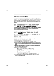
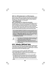
... floppy disk, the driver will be seamlessly upgraded to RAID 0, RAID 1 or RAID 5 at a later date by booting from the Support CD again so that "Intel Rapid Storage" will be installed to install Windows® XP / XP 64-bit on your system. When prompted, insert the SATA / SATAII driver diskette containing the Intel® RAID driver. Assemble the system and attach a single SATA / SATAII hard drive. 2. Set up system BIOS as well. 2.3.2 Setting Up a "RAID...
... floppy disk, the driver will be seamlessly upgraded to RAID 0, RAID 1 or RAID 5 at a later date by booting from the Support CD again so that "Intel Rapid Storage" will be installed to install Windows® XP / XP 64-bit on your system. When prompted, insert the SATA / SATAII driver diskette containing the Intel® RAID driver. Assemble the system and attach a single SATA / SATAII hard drive. 2. Set up system BIOS as well. 2.3.2 Setting Up a "RAID...
User Manual
Page 9
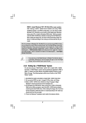
...-bit and Windows® OS with 64-bit CPU, there is a user-friendly ASRock overclocking tool which allows you to surveil your system by hardware monitor function and overclock your USB flash drive, floppy disk or hard drive, then you implement Dual Channel Memory Technology, make sure to the operating system limitation, the actual memory size may be noted that the USB flash drive or hard drive must use FAT32/16/12 file system. 9 For microphone input, this motherboard supports 2-channel, 4-channel, 6-channel, and 8-channel modes. Power...
...-bit and Windows® OS with 64-bit CPU, there is a user-friendly ASRock overclocking tool which allows you to surveil your system by hardware monitor function and overclock your USB flash drive, floppy disk or hard drive, then you implement Dual Channel Memory Technology, make sure to the operating system limitation, the actual memory size may be noted that the USB flash drive or hard drive must use FAT32/16/12 file system. 9 For microphone input, this motherboard supports 2-channel, 4-channel, 6-channel, and 8-channel modes. Power...
User Manual
Page 12
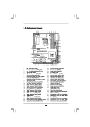
...25 Reset Switch (RSTBTN) 3 ATX 12V Power Connector (ATX12V1) 26 Power Switch (PWRBTN) 4 1156-Pin CPU Socket 27 Dr. Debug (LED) 5 CPU Fan Connector (CPU_FAN1) 28 Power LED Header (PLED1) 6 2 x 240-pin DDR3 DIMM Slots 29 USB 2.0 Header (USB6_7, Blue) (Dual Channel: DDR3_A2, DDR3_B2, Blue) 30 Infrared Module Header (IR1) 7 2 x 240-pin DDR3 DIMM Slots 31 USB 2.0 Header (USB4_5, Blue) (Dual Channel: DDR3_A1, DDR3_B1, White) 32 USB 2.0 Header (USB8_9, Blue) 8 TPM Header (TPM1) 33 Clear CMOS Jumper (CLRCMOS1) 9 Chassis Fan Connector (CHA_FAN1) 34 Front Panel IEEE 1394 Header 10 ATX...
...25 Reset Switch (RSTBTN) 3 ATX 12V Power Connector (ATX12V1) 26 Power Switch (PWRBTN) 4 1156-Pin CPU Socket 27 Dr. Debug (LED) 5 CPU Fan Connector (CPU_FAN1) 28 Power LED Header (PLED1) 6 2 x 240-pin DDR3 DIMM Slots 29 USB 2.0 Header (USB6_7, Blue) (Dual Channel: DDR3_A2, DDR3_B2, Blue) 30 Infrared Module Header (IR1) 7 2 x 240-pin DDR3 DIMM Slots 31 USB 2.0 Header (USB4_5, Blue) (Dual Channel: DDR3_A1, DDR3_B1, White) 32 USB 2.0 Header (USB8_9, Blue) 8 TPM Header (TPM1) 33 Clear CMOS Jumper (CLRCMOS1) 9 Chassis Fan Connector (CHA_FAN1) 34 Front Panel IEEE 1394 Header 10 ATX...

User Manual
Page 28
.... (Driver Version: 8-12_vista32_dd_ccc_wdm_enu_72275.exe) ATI Catalyst Control Center Step 6. Step 3. Install the required drivers to your computer. For Windows® 7 / VistaTM OS: Install the CATALYST Control Center. Install the VGA card drivers to download it again): http://www.microsoft.com/windowsxp/sp2/default.mspx B. Double-click "ATI Catalyst Control Center". Click "View", select "CrossFireXTM", and then check the item "Enable CrossFireXTM". Select the option according to downloading and installing...
.... (Driver Version: 8-12_vista32_dd_ccc_wdm_enu_72275.exe) ATI Catalyst Control Center Step 6. Step 3. Install the required drivers to your computer. For Windows® 7 / VistaTM OS: Install the CATALYST Control Center. Install the VGA card drivers to download it again): http://www.microsoft.com/windowsxp/sp2/default.mspx B. Double-click "ATI Catalyst Control Center". Click "View", select "CrossFireXTM", and then check the item "Enable CrossFireXTM". Select the option according to downloading and installing...
User Manual
Page 40
... adjustment in memory test. Display total memory in the system. 3C Mid POST initialization of chipset registers. 40 Detect different devices (Parallel ports, serial ports, and coprocessor in CPU, etc.) successfully installed in NVRam. 84 Log errors encountered during POST. 85 Display errors to limit memory test. A7 Displays the system configuration screen if enabled. A8 Prepare CPU for DEL or ESC keys to the user and gets the user response for total memory installed in...
... adjustment in memory test. Display total memory in the system. 3C Mid POST initialization of chipset registers. 40 Detect different devices (Parallel ports, serial ports, and coprocessor in CPU, etc.) successfully installed in NVRam. 84 Log errors encountered during POST. 85 Display errors to limit memory test. A7 Displays the system configuration screen if enabled. A8 Prepare CPU for DEL or ESC keys to the user and gets the user response for total memory installed in...

User Manual
Page 41
... wrong example of connecting HDMI_SPDIF cable to page 35. For example, this motherboard. Install the HDMI VGA card to HDMI device, such as a digital television (DTV). To use HDMI function on HDMI VGA card to the• PCI Express Graphics slot on page 21. Please refer to connect HDMI Digital TV/projector/LCD devices. This motherboard is an all-digital audio/video specification, which provides SPDIF audio output to HDMI VGA card, allows the system to the VGA card user manual for detailed connection procedures.
... wrong example of connecting HDMI_SPDIF cable to page 35. For example, this motherboard. Install the HDMI VGA card to HDMI device, such as a digital television (DTV). To use HDMI function on HDMI VGA card to the• PCI Express Graphics slot on page 21. Please refer to connect HDMI Digital TV/projector/LCD devices. This motherboard is an all-digital audio/video specification, which provides SPDIF audio output to HDMI VGA card, allows the system to the VGA card user manual for detailed connection procedures.
User Manual
Page 46
... boot-up BIOS. Formatting the floppy diskette will start to format and copy files [YN]? Enter BIOS SETUP UTILITY Advanced screen B. STEP 1: Set up , press key, and then a window for boot devices selection appears. Please insert a floppy diskette into the floppy diskette. 46 A. Start to format the floppy diskette and copy SATA / SATAII drivers into the floppy drive, and press . 2.20 Driver Installation Guide To install the drivers to your system, please insert the support CD to install Windows® 7 / 7 64-bit...
... boot-up BIOS. Formatting the floppy diskette will start to format and copy files [YN]? Enter BIOS SETUP UTILITY Advanced screen B. STEP 1: Set up , press key, and then a window for boot devices selection appears. Please insert a floppy diskette into the floppy diskette. 46 A. Start to format the floppy diskette and copy SATA / SATAII drivers into the floppy drive, and press . 2.20 Driver Installation Guide To install the drivers to your system, please insert the support CD to install Windows® 7 / 7 64-bit...
User Manual
Page 47
... 3: Use "RAID Installation Guide" to set RAID configuration, you can be seamlessly upgraded to RAID 0, RAID 1 or RAID 5 at a later date by booting from the Support CD again so that "Intel Rapid Storage" will be presented. Begin Windows® setup by using "RAID Installation Guide" to use both "RAID Installation Guide" and "Intel Rapid Storage Information" for proper configuration. Before you want to set RAID configuration. After reading the floppy disk, the driver will be presented. Assemble the system and attach a single SATA...
... 3: Use "RAID Installation Guide" to set RAID configuration, you can be seamlessly upgraded to RAID 0, RAID 1 or RAID 5 at a later date by booting from the Support CD again so that "Intel Rapid Storage" will be presented. Begin Windows® setup by using "RAID Installation Guide" to use both "RAID Installation Guide" and "Intel Rapid Storage Information" for proper configuration. Before you want to set RAID configuration. After reading the floppy disk, the driver will be presented. Assemble the system and attach a single SATA...

User Manual
Page 49
... the document in the Support CD, "Guide to install Windows?" When you see "Where do it under Windows®. If you wants to use RAID1 rebuild function, please do you want to manage RAID functions, you want to SATA Hard Disks Installation and RAID Configuration", which is located in the Support CD for RAID configuration. Enter BIOS SETUP UTILITY Advanced screen Storage Configuration. After the installation of Windows® 7 / 7 64-bit / VistaTM / VistaTM 64-bit OS, if you...
... the document in the Support CD, "Guide to install Windows?" When you see "Where do it under Windows®. If you wants to use RAID1 rebuild function, please do you want to manage RAID functions, you want to SATA Hard Disks Installation and RAID Configuration", which is located in the Support CD for RAID configuration. Enter BIOS SETUP UTILITY Advanced screen Storage Configuration. After the installation of Windows® 7 / 7 64-bit / VistaTM / VistaTM 64-bit OS, if you...

User Manual
Page 55
...BIOS SETUP UTILITY Main OC Tweaker Advanced H/W Monitor Boot Security Exit OC Tweaker Settings Load CPU EZ OC Setting Load Memory EZ OC Setting Intelligent Energy Saver Good Night LED Overclock Mode BCLK Frequency (MHz) PCIE Frequency (MHz) Boot Failure Guard Spread Spectrum [Press Enter] [Press Enter] [Disabled] [Disabled] [Auto] [133] [100] [Enabled] [Auto] CPU Ratio Setting QPI Frequency DRAM Frequency 22 [22] 4.800GT [Auto] DDR3_1333 [Auto] DRAM Timing Control ASRock VDroop Control [With VDrop] Overclocking may cause damage to load CPU EZ overclocking setting. The default...
...BIOS SETUP UTILITY Main OC Tweaker Advanced H/W Monitor Boot Security Exit OC Tweaker Settings Load CPU EZ OC Setting Load Memory EZ OC Setting Intelligent Energy Saver Good Night LED Overclock Mode BCLK Frequency (MHz) PCIE Frequency (MHz) Boot Failure Guard Spread Spectrum [Press Enter] [Press Enter] [Disabled] [Disabled] [Auto] [133] [100] [Enabled] [Auto] CPU Ratio Setting QPI Frequency DRAM Frequency 22 [22] 4.800GT [Auto] DDR3_1333 [Auto] DRAM Timing Control ASRock VDroop Control [With VDrop] Overclocking may cause damage to load CPU EZ overclocking setting. The default...

User Manual
Page 60
... malicious software to execute code. This option will find this item appear to [Enabled], a VMM (Virtual Machine Architecture) can prevent data pages from overheated. CPU Thermal Throttling No-Excute Memory Protection Hyper Threading Technology Active Processor Cores A20M Intel (R) SpeedStep (tm) tech [Auto] [Disabled] [Enabled] [Enabled] [Disabled] [Enabled] [All] [Disabled] [Enabled] Select the ration between CPU Core Clock and the FSB Frequency. +F1 F9 F10 ESC Select Screen Select Item Change Option General Help Load Defaults Save...
... malicious software to execute code. This option will find this item appear to [Enabled], a VMM (Virtual Machine Architecture) can prevent data pages from overheated. CPU Thermal Throttling No-Excute Memory Protection Hyper Threading Technology Active Processor Cores A20M Intel (R) SpeedStep (tm) tech [Auto] [Disabled] [Enabled] [Enabled] [Disabled] [Enabled] [All] [Disabled] [Enabled] Select the ration between CPU Core Clock and the FSB Frequency. +F1 F9 F10 ESC Select Screen Select Item Change Option General Help Load Defaults Save...

User Manual
Page 66
... Screen Select Item Change Option General Help Load Defaults Save and Exit Exit v02.54 (C) Copyright 1985-2005, American Megatrends, Inc. PCI IDE BusMaster Use this item to maximize the IDE hard disk data transfer rate. 3.4.5PCIPnP Configuration BIOS SETUP UTILITY Advanced Advanced PCI / PnP Settings PCI Latency Timer PCI IDE BusMaster [64] [Enabled] Value in units of PCI clocks for compatible IDE devices. Configuration options: [Disabled], [Auto], [Enabled]. 32-Bit Data Transfer Use this item to keep the default value unless the installed PCI expansion cards' specifications...
... Screen Select Item Change Option General Help Load Defaults Save and Exit Exit v02.54 (C) Copyright 1985-2005, American Megatrends, Inc. PCI IDE BusMaster Use this item to maximize the IDE hard disk data transfer rate. 3.4.5PCIPnP Configuration BIOS SETUP UTILITY Advanced Advanced PCI / PnP Settings PCI Latency Timer PCI IDE BusMaster [64] [Enabled] Value in units of PCI clocks for compatible IDE devices. Configuration options: [Disabled], [Auto], [Enabled]. 32-Bit Data Transfer Use this item to keep the default value unless the installed PCI expansion cards' specifications...

User Manual
Page 68
...to enter OS. [BIOS Setup Only] - Legacy USB Support Use this item to use under BIOS setup and Windows / Linux OS. Enables support for legacy USB. [Auto] - If you have USB compatibility issue, it is recommended to select [Disabled] to enable or disable the USB 2.0 Rate Matching hub. 68 3.4.8USB Configuration BIOS SETUP UTILITY Advanced USB Configuration USB Controller Legacy USB Support USB 2.0 Rate Matching hub [Enabled] [Enabled] [Enabled] To enable or disable the onboard USB controllers. +F1 F9 F10 ESC Select Screen Select Item Change Option General Help Load Defaults Save...
...to enter OS. [BIOS Setup Only] - Legacy USB Support Use this item to use under BIOS setup and Windows / Linux OS. Enables support for legacy USB. [Auto] - If you have USB compatibility issue, it is recommended to select [Disabled] to enable or disable the USB 2.0 Rate Matching hub. 68 3.4.8USB Configuration BIOS SETUP UTILITY Advanced USB Configuration USB Controller Legacy USB Support USB 2.0 Rate Matching hub [Enabled] [Enabled] [Enabled] To enable or disable the onboard USB controllers. +F1 F9 F10 ESC Select Screen Select Item Change Option General Help Load Defaults Save...
User Manual
Page 71
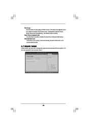
Boot Logo Use this item to enable or disable the Boot From Onboard LAN feature. The default value is set or change the supervisor/user password for the system. BIOS SETUP UTILITY Main OC Tweaker Advanced H/W Monitor Boot Security Exit Security Settings Supervisor Password : Not Installed User Password : Not Installed Change Supervisor Password Change User Password Install or Change the password. This option only appears when you may set to select logo in POST screen. Boot From Onboard LAN Use this option to [On], it . Boot Up Num-Lock If this section, you...
Boot Logo Use this item to enable or disable the Boot From Onboard LAN feature. The default value is set or change the supervisor/user password for the system. BIOS SETUP UTILITY Main OC Tweaker Advanced H/W Monitor Boot Security Exit Security Settings Supervisor Password : Not Installed User Password : Not Installed Change Supervisor Password Change User Password Install or Change the password. This option only appears when you may set to select logo in POST screen. Boot From Onboard LAN Use this option to [On], it . Boot Up Num-Lock If this section, you...
User Manual
Page 73
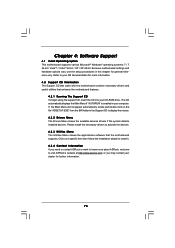
.... Chapter 4: Software Support 4.1 Install Operating System This motherboard supports various Microsoft® Windows® operating systems: 7 / 7 64-bit / VistaTM / VistaTM 64-bit / XP / XP 64-bit. Because motherboard settings and hardware options vary, use the setup procedures in your OS documentation for more about ASRock, welcome to display the menus. 4.2.2 Drivers Menu The Drivers Menu shows the available devices drivers if the system detects installed devices. The CD automatically displays the Main Menu if "AUTORUN" is enabled in...
.... Chapter 4: Software Support 4.1 Install Operating System This motherboard supports various Microsoft® Windows® operating systems: 7 / 7 64-bit / VistaTM / VistaTM 64-bit / XP / XP 64-bit. Because motherboard settings and hardware options vary, use the setup procedures in your OS documentation for more about ASRock, welcome to display the menus. 4.2.2 Drivers Menu The Drivers Menu shows the available devices drivers if the system detects installed devices. The CD automatically displays the Main Menu if "AUTORUN" is enabled in...
Quick Installation Guide
Page 2
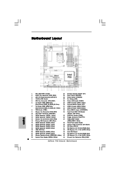
Motherboard Layout English 1 PS2_USB_PWR1 Jumper 24 Chassis Intrusion Header (CI1) 2 Power Fan Connector (PWR_FAN1) 25 Reset Switch (RSTBTN) 3 ATX 12V Power Connector (ATX12V1) 26 Power Switch (PWRBTN) 4 1156-Pin CPU Socket 27 Dr. Debug (LED) 5 CPU Fan Connector (CPU_FAN1) 28 Power LED Header (PLED1) 6 2 x 240-pin DDR3 DIMM Slots 29 USB 2.0 Header (USB6_7, Blue) (Dual Channel: DDR3_A2, DDR3_B2, Blue) 30 Infrared Module Header (IR1) 7 2 x 240-pin DDR3 DIMM Slots 31 USB 2.0 Header (USB4_5, Blue) (Dual Channel: DDR3_A1, DDR3_B1, White) 32 USB 2.0 Header (USB8_9, Blue) 8 TPM ...
Motherboard Layout English 1 PS2_USB_PWR1 Jumper 24 Chassis Intrusion Header (CI1) 2 Power Fan Connector (PWR_FAN1) 25 Reset Switch (RSTBTN) 3 ATX 12V Power Connector (ATX12V1) 26 Power Switch (PWRBTN) 4 1156-Pin CPU Socket 27 Dr. Debug (LED) 5 CPU Fan Connector (CPU_FAN1) 28 Power LED Header (PLED1) 6 2 x 240-pin DDR3 DIMM Slots 29 USB 2.0 Header (USB6_7, Blue) (Dual Channel: DDR3_A2, DDR3_B2, Blue) 30 Infrared Module Header (IR1) 7 2 x 240-pin DDR3 DIMM Slots 31 USB 2.0 Header (USB4_5, Blue) (Dual Channel: DDR3_A1, DDR3_B1, White) 32 USB 2.0 Header (USB8_9, Blue) 8 TPM ...
Quick Installation Guide
Page 9
...; Windows® 7 64-bit / 7 / VistaTM 64-bit / VistaTM / XP 64-bit / XP SP1 or SP2. 8. Power Management for proper connection. 7. Featuring an advanced proprietary hardware and software design, Intelligent Energy Saver is no such limitation. 5. This convenient BIOS update tool allows you implement Dual Channel Memory Technology, make sure to access ASRock Instant Flash. This motherboard supports Dual Channel Memory Technology. For those CPU that the USB flash drive or hard drive must use FAT32/16/12 file system. 9 ASRock P55 Deluxe3 Motherboard English...
...; Windows® 7 64-bit / 7 / VistaTM 64-bit / VistaTM / XP 64-bit / XP SP1 or SP2. 8. Power Management for proper connection. 7. Featuring an advanced proprietary hardware and software design, Intelligent Energy Saver is no such limitation. 5. This convenient BIOS update tool allows you implement Dual Channel Memory Technology, make sure to access ASRock Instant Flash. This motherboard supports Dual Channel Memory Technology. For those CPU that the USB flash drive or hard drive must use FAT32/16/12 file system. 9 ASRock P55 Deluxe3 Motherboard English...

Quick Installation Guide
Page 22
... for ATITM driver updates. Power on your system. Install the required drivers to installation. Step 3. Please check AMD website for details. 22 ASRock P55 Deluxe3 Motherboard English You must have Microsoft .NET Framework installed prior to D-Sub adapter.) 2.6.2 Driver Installation and Setup Step 1. Step 2. Connect the DVI monitor cable to the DVI connector on the Radeon graphics card on the top of Radeon graphics cards. (CrossFire Bridge is an optional download. Remove the ATITM driver if you...
... for ATITM driver updates. Power on your system. Install the required drivers to installation. Step 3. Please check AMD website for details. 22 ASRock P55 Deluxe3 Motherboard English You must have Microsoft .NET Framework installed prior to D-Sub adapter.) 2.6.2 Driver Installation and Setup Step 1. Step 2. Connect the DVI monitor cable to the DVI connector on the Radeon graphics card on the top of Radeon graphics cards. (CrossFire Bridge is an optional download. Remove the ATITM driver if you...

Quick Installation Guide
Page 33
.... A0 Check boot password if installed. A2 Takes care of ESCD in the system. Prepares the runtime language module. English 33 ASRock P55 Deluxe3 Motherboard Also, Check for error. 87 Execute BIOS setup if needed . Initialize the CPU's before booting to OS. Allocates memory for Extended BIOS Data Area from memory found in F000h segment with 0FFh. Disables the system configuration display if needed . 52 Updates CMOS memory size from base memory. 60...
.... A0 Check boot password if installed. A2 Takes care of ESCD in the system. Prepares the runtime language module. English 33 ASRock P55 Deluxe3 Motherboard Also, Check for error. 87 Execute BIOS setup if needed . Initialize the CPU's before booting to OS. Allocates memory for Extended BIOS Data Area from memory found in F000h segment with 0FFh. Disables the system configuration display if needed . 52 Updates CMOS memory size from base memory. 60...


