User Manual
Page 6
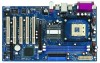
...5Gb/s data transfer rate (Not Support "RAID and "Hot Plug" functions) Floppy Port: Supports up to 2 floppy disk drives Audio: 5.1 channels AC'97 Audio PCI LAN: Speed: 802.3u (10/100 Ethernet), supports Wake-On-LAN Hardware Monitor: CPU temperature sensing, Chassis temperature sensing,... CPU overheat shutdown to protect CPU life (ASRock U-COP)(see CAUTION 3), CPU fan tachometer, Chassis fan tachometer, Voltage monitoring: +12V, +5V, +...
...5Gb/s data transfer rate (Not Support "RAID and "Hot Plug" functions) Floppy Port: Supports up to 2 floppy disk drives Audio: 5.1 channels AC'97 Audio PCI LAN: Speed: 802.3u (10/100 Ethernet), supports Wake-On-LAN Hardware Monitor: CPU temperature sensing, Chassis temperature sensing,... CPU overheat shutdown to protect CPU life (ASRock U-COP)(see CAUTION 3), CPU fan tachometer, Chassis fan tachometer, Voltage monitoring: +12V, +5V, +...

User Manual
Page 8
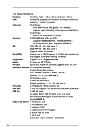
...Center: Line Out Bottom: Mic In USB 2.0 T: USB4 1 B: USB5 USB4_5 AUX1 CD1 1 AUDIO1 JR1 JL1 AUDIO CODEC 22 21 PCI LAN Super I/O 2MB BIOS 1 Intel 848 Chipset IDE2 IDE1 1.5V_AGP1 P4i48 PCI 1 FSB800DDR400 PCI 2 USB2.0 AGP8X Intel ICH5 PCI 3 5.1CH SATA CLRCMOS0 PCI 4 SATA1 SATA2 CMOS Battery ... 20 Game Port Connector (GAME1) 21 BIOS FWH Chip 22 PCI Slots (PCI1- 5) 23 JL1 Jumper 24 JR1 Jumper 25 Front Panel Audio Header (AUDIO1) 26 Internal Audio Connector: AUX1 (White) 27 Internal Audio Connector: CD1 (Black) 28 Shared USB 2.0 Header (USB4_5, Blue) 29 CPU Fan Connector (CPU_FAN1) 8
...Center: Line Out Bottom: Mic In USB 2.0 T: USB4 1 B: USB5 USB4_5 AUX1 CD1 1 AUDIO1 JR1 JL1 AUDIO CODEC 22 21 PCI LAN Super I/O 2MB BIOS 1 Intel 848 Chipset IDE2 IDE1 1.5V_AGP1 P4i48 PCI 1 FSB800DDR400 PCI 2 USB2.0 AGP8X Intel ICH5 PCI 3 5.1CH SATA CLRCMOS0 PCI 4 SATA1 SATA2 CMOS Battery ... 20 Game Port Connector (GAME1) 21 BIOS FWH Chip 22 PCI Slots (PCI1- 5) 23 JL1 Jumper 24 JR1 Jumper 25 Front Panel Audio Header (AUDIO1) 26 Internal Audio Connector: AUX1 (White) 27 Internal Audio Connector: CD1 (Black) 28 Shared USB 2.0 Header (USB4_5, Blue) 29 CPU Fan Connector (CPU_FAN1) 8

User Manual
Page 14
... BIOS, you must boot up events. The illustration shows a 3-pin jumper whose pin1 and pin2 are short, both the front panel and the rear panel audio connectors can work. Please rem ember to enable (see p.8 No. 23) JR1 JL1 Note: If the jumpers JL1 and JR1 are "Short" when jumper cap...
... BIOS, you must boot up events. The illustration shows a 3-pin jumper whose pin1 and pin2 are short, both the front panel and the rear panel audio connectors can work. Please rem ember to enable (see p.8 No. 23) JR1 JL1 Note: If the jumpers JL1 and JR1 are "Short" when jumper cap...
User Manual
Page 16
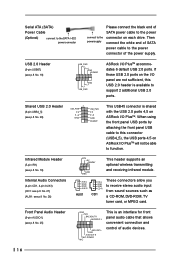
... 2.0 ports on the I/O panel are not sufficient, this connector (USB4_5), the USB ports 4,5 on ASRock I /O PlusTM accommodates 6 default USB 2.0 ports. Infrared Module Header (5-pin IR1) (see p.8 No. 18) Internal Audio Connectors (4-pin CD1, 4-pin AUX1) (CD1: see p.8 No. 27) (AUX1: see p.8 No...Shared USB 2.0 Header (9-pin USB4_5) (see p.8 No. 19) USB_PWR P-6 P+6 GND DUMMY 1 GND P+7 P-7 USB_PWR ASRock I /O PlusTM will not be able to function. L GND A U D - Front Panel Audio Header (9-pin AUDIO1) (see p.8 No. 26) IRTX +5V DUMMY 1 GND IRRX This header supports an optional wireless...
... 2.0 ports on the I/O panel are not sufficient, this connector (USB4_5), the USB ports 4,5 on ASRock I /O PlusTM accommodates 6 default USB 2.0 ports. Infrared Module Header (5-pin IR1) (see p.8 No. 18) Internal Audio Connectors (4-pin CD1, 4-pin AUX1) (CD1: see p.8 No. 27) (AUX1: see p.8 No...Shared USB 2.0 Header (9-pin USB4_5) (see p.8 No. 19) USB_PWR P-6 P+6 GND DUMMY 1 GND P+7 P-7 USB_PWR ASRock I /O PlusTM will not be able to function. L GND A U D - Front Panel Audio Header (9-pin AUDIO1) (see p.8 No. 26) IRTX +5V DUMMY 1 GND IRRX This header supports an optional wireless...
User Manual
Page 34
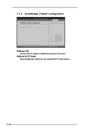
OnBoard LAN Use this item to enable or disable the onboard LAN device. 3.7.2 SouthBridge Chipset Configuration BIOS SETUP UTILITY SouthBridge Chipset Configuration Onboard LAN Onboard AC97 Audio [Enabled] [Auto] Chipset Enable / Disable onboard LAN. +F1 F9 F10 ESC Select Screen Select Item Change Option General Help Load Defaults Save and Exit Exit v02.54 (C) Copyright 1985-2003, American Megatrends, Inc. OnBoard AC'97 Audio Select [Disabled] or [Auto] for the onboard AC'97 Audio feature. 34
OnBoard LAN Use this item to enable or disable the onboard LAN device. 3.7.2 SouthBridge Chipset Configuration BIOS SETUP UTILITY SouthBridge Chipset Configuration Onboard LAN Onboard AC97 Audio [Enabled] [Auto] Chipset Enable / Disable onboard LAN. +F1 F9 F10 ESC Select Screen Select Item Change Option General Help Load Defaults Save and Exit Exit v02.54 (C) Copyright 1985-2003, American Megatrends, Inc. OnBoard AC'97 Audio Select [Disabled] or [Auto] for the onboard AC'97 Audio feature. 34


