User Manual
Page 3
...1.2 Specifications 6 1.3 Motherboard Layout 8 1.4 ASRock I/O PlusTM 9 2 Installation 10 Pre-installation Precautions 10 2.1 CPU Installation 11 2.2 Installation of CPU Fan and Heatsink 11 2.3 Installation of Memory Modules (DIMM 12 2.4 Expansion Slots (PCI and AGP Slots 13 2.5 Jumpers Setup 14 2.6 Onboard Headers and Connectors 15 2.7 Serial ATA (SATA) Hard Disks Installation 18 2.8 Making An SATA Driver Diskette 18 3 BIOS SETUP UTILITY 19 3.1 Introduction 19 3.1.1 BIOS Menu Bar 19 3.1.2 Navigation Keys 20 3.2 Main Screen 20 3.3 Advanced Screen 21 3.3.1 CPU Configuration 21...
...1.2 Specifications 6 1.3 Motherboard Layout 8 1.4 ASRock I/O PlusTM 9 2 Installation 10 Pre-installation Precautions 10 2.1 CPU Installation 11 2.2 Installation of CPU Fan and Heatsink 11 2.3 Installation of Memory Modules (DIMM 12 2.4 Expansion Slots (PCI and AGP Slots 13 2.5 Jumpers Setup 14 2.6 Onboard Headers and Connectors 15 2.7 Serial ATA (SATA) Hard Disks Installation 18 2.8 Making An SATA Driver Diskette 18 3 BIOS SETUP UTILITY 19 3.1 Introduction 19 3.1.1 BIOS Menu Bar 19 3.1.2 Navigation Keys 20 3.2 Main Screen 20 3.3 Advanced Screen 21 3.3.1 CPU Configuration 21...
User Manual
Page 5
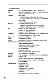
... ASRock P4i48 Motherboard (ATX Form Factor: 12.0-in x 7.0-in, 30.5 cm x 17.8 cm) ASRock P4i48 Quick Installation Guide ASRock P4i48 Support CD One 80-conductor Ultra ATA 66/100 IDE Ribbon Cable One Ribbon Cable for purchasing ASRock P4i48 motherboard, a reliable motherboard produced under ASRock's consistently stringent quality control. In this manual, chapter 1 and 2 contain introduction of the Support CD. Chapter 1 Introduction Thank you for a 3.5-in Floppy Drive One Serial ATA (SATA) Data Cable One Serial ATA (SATA) HDD Power Cable (Optional) One ASRock...
... ASRock P4i48 Motherboard (ATX Form Factor: 12.0-in x 7.0-in, 30.5 cm x 17.8 cm) ASRock P4i48 Quick Installation Guide ASRock P4i48 Support CD One 80-conductor Ultra ATA 66/100 IDE Ribbon Cable One Ribbon Cable for purchasing ASRock P4i48 motherboard, a reliable motherboard produced under ASRock's consistently stringent quality control. In this manual, chapter 1 and 2 contain introduction of the Support CD. Chapter 1 Introduction Thank you for a 3.5-in Floppy Drive One Serial ATA (SATA) Data Cable One Serial ATA (SATA) HDD Power Cable (Optional) One ASRock...
User Manual
Page 6
... DMA Mode 5 Supports up to 4 IDE devices Serial ATA: Supports up to 2 SATA devices at 1.5Gb/s data transfer rate (Not Support "RAID and "Hot Plug" functions) Floppy Port: Supports up to 2 floppy disk drives Audio: 5.1 channels AC'97 Audio PCI LAN: Speed: 802.3u (10/100 Ethernet), supports Wake-On-LAN Hardware Monitor: CPU temperature sensing, Chassis temperature sensing, CPU overheat shutdown to protect CPU life (ASRock U-COP)(see CAUTION 3), CPU fan tachometer, Chassis fan tachometer, Voltage monitoring: +12V, +5V, +3V, Vcore PCI slots: 5 PCI slots with PCI Specification...
... DMA Mode 5 Supports up to 4 IDE devices Serial ATA: Supports up to 2 SATA devices at 1.5Gb/s data transfer rate (Not Support "RAID and "Hot Plug" functions) Floppy Port: Supports up to 2 floppy disk drives Audio: 5.1 channels AC'97 Audio PCI LAN: Speed: 802.3u (10/100 Ethernet), supports Wake-On-LAN Hardware Monitor: CPU temperature sensing, Chassis temperature sensing, CPU overheat shutdown to protect CPU life (ASRock U-COP)(see CAUTION 3), CPU fan tachometer, Chassis fan tachometer, Voltage monitoring: +12V, +5V, +3V, Vcore PCI slots: 5 PCI slots with PCI Specification...
User Manual
Page 7
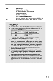
... memory module. 3. Power Management for USB 2.0 works fine under Microsoft® Windows® 98/ ME. While CPU overheat is not recommended to perform over-clocking. Although this motherboard offers stepless control, it back again. BIOS: OS: AMI legal BIOS, Supports "Plug and Play", ACPI 1.1 compliance wake up events, Supports jumperfree, SMBIOS 2.3.1 support, CPU frequency stepless control (only for the memory support frequency and its corresponding CPU FSB frequency. It may not work properly under Microsoft® Windows...
... memory module. 3. Power Management for USB 2.0 works fine under Microsoft® Windows® 98/ ME. While CPU overheat is not recommended to perform over-clocking. Although this motherboard offers stepless control, it back again. BIOS: OS: AMI legal BIOS, Supports "Plug and Play", ACPI 1.1 compliance wake up events, Supports jumperfree, SMBIOS 2.3.1 support, CPU frequency stepless control (only for the memory support frequency and its corresponding CPU FSB frequency. It may not work properly under Microsoft® Windows...

User Manual
Page 8
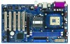
... AUDIO CODEC 22 21 PCI LAN Super I/O 2MB BIOS 1 Intel 848 Chipset IDE2 IDE1 1.5V_AGP1 P4i48 PCI 1 FSB800DDR400 PCI 2 USB2.0 AGP8X Intel ICH5 PCI 3 5.1CH SATA CLRCMOS0 PCI 4 SATA1 SATA2 CMOS Battery CHA_FAN1 PCI 5 GAME1 FLOPPY1 USB67 1 SPEAKER1 1 IR1 1 PLED PWRBTN PANEL 1 1 HDLED RESET 9 10 11 12 13 14 15 16 20 1 PS2_USB_PWR1 Jumper 2 CPU Socket 3 CPU Heatsink Retention Module 4 North Bridge Controller 5 184-pin DDR DIMM Slots (DDR1- 2) 6 ATX Power Connector (ATXPWR1) 7 Secondary IDE Connector (IDE2, Black) 8 Primary IDE Connector...
... AUDIO CODEC 22 21 PCI LAN Super I/O 2MB BIOS 1 Intel 848 Chipset IDE2 IDE1 1.5V_AGP1 P4i48 PCI 1 FSB800DDR400 PCI 2 USB2.0 AGP8X Intel ICH5 PCI 3 5.1CH SATA CLRCMOS0 PCI 4 SATA1 SATA2 CMOS Battery CHA_FAN1 PCI 5 GAME1 FLOPPY1 USB67 1 SPEAKER1 1 IR1 1 PLED PWRBTN PANEL 1 1 HDLED RESET 9 10 11 12 13 14 15 16 20 1 PS2_USB_PWR1 Jumper 2 CPU Socket 3 CPU Heatsink Retention Module 4 North Bridge Controller 5 184-pin DDR DIMM Slots (DDR1- 2) 6 ATX Power Connector (ATXPWR1) 7 Secondary IDE Connector (IDE2, Black) 8 Primary IDE Connector...
User Manual
Page 13
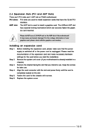
... P4i48 motherboard. Remove the bracket facing the slot that you start the installation. AGP slot: The AGP slot is unplugged. Please do NOT use . Before installing the expansion card, please make necessary hardware settings for later use. Step 3. Fasten the card to install a graphics card. Step 2. Replace the system cover. 13 PCI slots: PCI slots are 5 PCI slots and 1 AGP slot on the slot. Align the card connector with the slot and press firmly until the card is already installed in a chassis...
... P4i48 motherboard. Remove the bracket facing the slot that you start the installation. AGP slot: The AGP slot is unplugged. Please do NOT use . Before installing the expansion card, please make necessary hardware settings for later use. Step 3. Fasten the card to install a graphics card. Step 2. Replace the system cover. 13 PCI slots: PCI slots are 5 PCI slots and 1 AGP slot on the slot. Align the card connector with the slot and press firmly until the card is already installed in a chassis...
User Manual
Page 16
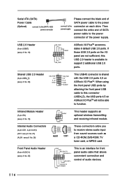
... USB 2.0 ports on the I/O panel are not sufficient, this connector (USB4_5), the USB ports 4,5 on ASRock I /O PlusTM will not be able to receive stereo audio input from sound sources such as a CD-ROM, DVD-ROM, TV tuner card, or MPEG card. L GND A U D - Then powersupply connect the white end of SATA power cable to the power connector of audio devices. 16 Front Panel Audio Header (9-pin AUDIO1) (see p.8 No. 26) IRTX +5V DUMMY 1 GND IRRX This header supports an optional...
... USB 2.0 ports on the I/O panel are not sufficient, this connector (USB4_5), the USB ports 4,5 on ASRock I /O PlusTM will not be able to receive stereo audio input from sound sources such as a CD-ROM, DVD-ROM, TV tuner card, or MPEG card. L GND A U D - Then powersupply connect the white end of SATA power cable to the power connector of audio devices. 16 Front Panel Audio Header (9-pin AUDIO1) (see p.8 No. 26) IRTX +5V DUMMY 1 GND IRRX This header supports an optional...
User Manual
Page 18
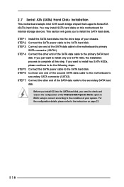
... chassis. You may install SATA hard disks on page 23. 18 STEP 3: Connect one end of the SATA data cable to check and ensure the configuration of the OnBoard IDE Operate Mode option in BIOS setup is complete at this motherboard for internal storage devices. STEP 6: Connect one end of the second SATA data cable to the instruction on this step. STEP 5: Connect the SATA power cable to the SATA hard disk. For the configuration details, please refer to the motherboard's secondary SATA connector...
... chassis. You may install SATA hard disks on page 23. 18 STEP 3: Connect one end of the SATA data cable to check and ensure the configuration of the OnBoard IDE Operate Mode option in BIOS setup is complete at this motherboard for internal storage devices. STEP 6: Connect one end of the second SATA data cable to the instruction on this step. STEP 5: Connect the SATA power cable to the SATA hard disk. For the configuration details, please refer to the motherboard's secondary SATA connector...
User Manual
Page 19
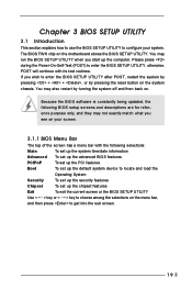
... the Power-On-Self-Test (POST) to configure your screen. 3.1.1 BIOS Menu Bar The top of the screen has a menu bar with its test routines. Because the BIOS software is constantly being updated, the following selections: Main To set up the system time/date information Advanced To set up the advanced BIOS features PCIPnP To set up the PCI features Boot To set up the default system device to enter the BIOS SETUP UTILITY after POST...
... the Power-On-Self-Test (POST) to configure your screen. 3.1.1 BIOS Menu Bar The top of the screen has a menu bar with its test routines. Because the BIOS software is constantly being updated, the following selections: Main To set up the system time/date information Advanced To set up the advanced BIOS features PCIPnP To set up the PCI features Boot To set up the default system device to enter the BIOS SETUP UTILITY after POST...

User Manual
Page 21
... Technology [Auto] Select how to Sub Screen F1 General Help F9 Load Defaults F10 Save and Exit ESC Exit v02.54 (C) Copyright 1985-2003, American Megatrends, Inc. CPU Configuration IDE Configuration Floppy Configuration SuperIO Configuration Hardware Health Configuration ACPI Configuration USB Configuration Configure CPU Select Screen Select Item Enter Go to set the configurations for better system stability. 21 Spread Spectrum This item should always be [Disabled] for the following item. Main BIOS SETUP UTILITY Advanced PCI PnP Boot Security Chipset...
... Technology [Auto] Select how to Sub Screen F1 General Help F9 Load Defaults F10 Save and Exit ESC Exit v02.54 (C) Copyright 1985-2003, American Megatrends, Inc. CPU Configuration IDE Configuration Floppy Configuration SuperIO Configuration Hardware Health Configuration ACPI Configuration USB Configuration Configure CPU Select Screen Select Item Enter Go to set the configurations for better system stability. 21 Spread Spectrum This item should always be [Disabled] for the following item. Main BIOS SETUP UTILITY Advanced PCI PnP Boot Security Chipset...
User Manual
Page 23
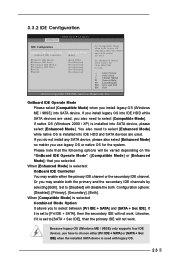
3.3.2 IDE Configuration Advanced BIOS SETUP UTILITY IDE Configuration OnBoard IDE Operate Mode OnBoard IDE Controller Primary IDE Master Primary IDE Slave Secondary IDE Master Secondary IDE Slave SATA1 SATA2 [Enhanced Mode] [Both] [Hard Disk] [Not Detected] [Not Detected] [Not Detected] [Not Detected] [Not Detected] Set [Compatible Mode] when both Legacy OS (MS-DOS, Win Me / 98SE) and SATA device are used . +F1 F9 F10 ESC Select Screen Select Item Change Option General Help Load Defaults Save and Exit Exit v02.54 (C) Copyright 1985-2003...
3.3.2 IDE Configuration Advanced BIOS SETUP UTILITY IDE Configuration OnBoard IDE Operate Mode OnBoard IDE Controller Primary IDE Master Primary IDE Slave Secondary IDE Master Secondary IDE Slave SATA1 SATA2 [Enhanced Mode] [Both] [Hard Disk] [Not Detected] [Not Detected] [Not Detected] [Not Detected] [Not Detected] Set [Compatible Mode] when both Legacy OS (MS-DOS, Win Me / 98SE) and SATA device are used . +F1 F9 F10 ESC Select Screen Select Item Change Option General Help Load Defaults Save and Exit Exit v02.54 (C) Copyright 1985-2003...
User Manual
Page 24
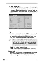
... BIOS, use a disk utility, such as the example in the following instruction, which can write or read data from the hard disk. We will use of IDE device. [Auto]: Select [Auto] to automatically detect the hard disk drive. Configuration options: [Not Installed], [Auto], [CD/DVD], and [ARMD]. [Not Installed]: Select [Not Installed] to disable the use the "Primary IDE Master" as FDISK, to partition and format the new IDE hard disk drives. IDE Device Configuration You may set the partition of the Primary IDE hard disk drives...
... BIOS, use a disk utility, such as the example in the following instruction, which can write or read data from the hard disk. We will use of IDE device. [Auto]: Select [Auto] to automatically detect the hard disk drive. Configuration options: [Not Installed], [Auto], [CD/DVD], and [ARMD]. [Not Installed]: Select [Not Installed] to disable the use the "Primary IDE Master" as FDISK, to partition and format the new IDE hard disk drives. IDE Device Configuration You may set the partition of the Primary IDE hard disk drives...
User Manual
Page 25
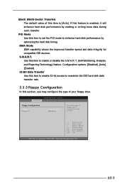
.... S.M.A.R.T. Configuration options: [Disabled], [Auto], [Enabled]. 32-Bit Data Transfer Use this item to enable 32-bit access to maximize the IDE hard disk data transfer rate. 3.3.3 Floppy Configuration In this item to the system. +F1 F9 F10 ESC Select Screen Select Item Change Option General Help Load Defaults Save and Exit Exit v02.54 (C) Copyright 1985-2003, American Megatrends, Inc. 25 BIOS SETUP UTILITY Advanced Floppy Configuration Floppy A Floppy B [1.44 MB 312"] [Disabled] Select the type of floppy drive connected to enable or disable...
.... S.M.A.R.T. Configuration options: [Disabled], [Auto], [Enabled]. 32-Bit Data Transfer Use this item to enable 32-bit access to maximize the IDE hard disk data transfer rate. 3.3.3 Floppy Configuration In this item to the system. +F1 F9 F10 ESC Select Screen Select Item Change Option General Help Load Defaults Save and Exit Exit v02.54 (C) Copyright 1985-2003, American Megatrends, Inc. 25 BIOS SETUP UTILITY Advanced Floppy Configuration Floppy A Floppy B [1.44 MB 312"] [Disabled] Select the type of floppy drive connected to enable or disable...
User Manual
Page 26
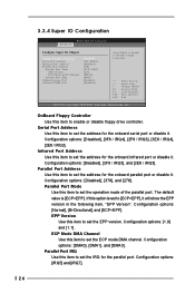
... enable or disable floppy drive controller. EPP Version Use this item to Enable or Disable Floppy Controller. +F1 F9 F10 ESC Select Screen Select Item Change Option General Help Load Defaults Save and Exit Exit v02.54 (C) Copyright 1985-2003, American Megatrends, Inc. Serial Port Address Use this item to set the address for the onboard infrared port or disable it. 3.3.4 Super IO Configuration Advanced BIOS SETUP UTILITY Configure Super IO Chipset OnBoard Floppy Controller Serial Port Address Infrared Port Address Parallel Port Address Parallel Port Mode EPP Version...
... enable or disable floppy drive controller. EPP Version Use this item to Enable or Disable Floppy Controller. +F1 F9 F10 ESC Select Screen Select Item Change Option General Help Load Defaults Save and Exit Exit v02.54 (C) Copyright 1985-2003, American Megatrends, Inc. Serial Port Address Use this item to set the address for the onboard infrared port or disable it. 3.3.4 Super IO Configuration Advanced BIOS SETUP UTILITY Configure Super IO Chipset OnBoard Floppy Controller Serial Port Address Infrared Port Address Parallel Port Address Parallel Port Mode EPP Version...
User Manual
Page 28
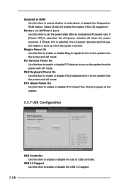
... system starts to power on the system. 3.3.7 USB Configuration BIOS SETUP UTILITY Advanced USB Configuration USB Devices Enabled : None USB Controller USB 2.0 Support Legacy USB Support [Enabled] [Enabled] [Disabled] To enable or disable the onboard USB controllers. +F1 F9 F10 ESC Select Screen Select Item Change Option General Help Load Defaults Save and Exit Exit v02.54 (C) Copyright 1985-2003, American Megatrends, Inc. Ring-In Power On Use this item to select whether to auto-detect or disable the Suspend-toRAM feature. RTC Alarm Power On Use this...
... system starts to power on the system. 3.3.7 USB Configuration BIOS SETUP UTILITY Advanced USB Configuration USB Devices Enabled : None USB Controller USB 2.0 Support Legacy USB Support [Enabled] [Enabled] [Disabled] To enable or disable the onboard USB controllers. +F1 F9 F10 ESC Select Screen Select Item Change Option General Help Load Defaults Save and Exit Exit v02.54 (C) Copyright 1985-2003, American Megatrends, Inc. Ring-In Power On Use this item to select whether to auto-detect or disable the Suspend-toRAM feature. RTC Alarm Power On Use this...
User Manual
Page 29
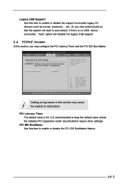
... USB device connected, "Auto" option will start to auto-detect; PCI Latency Timer PCI IDE BusMaster [64] [Enabled] Value in this item to enable or disable the support to emulate legacy I/O devices such as mouse, keyboard,... Setting wrong values in units of PCI clocks for PCI device latency timer register. +F1 F9 F10 ESC Select Screen Select Item Change Option General Help Load Defaults Save and Exit Exit v02.54 (C) Copyright 1985-2003, American Megatrends, Inc. Main Advanced BIOS SETUP UTILITY...
... USB device connected, "Auto" option will start to auto-detect; PCI Latency Timer PCI IDE BusMaster [64] [Enabled] Value in this item to enable or disable the support to emulate legacy I/O devices such as mouse, keyboard,... Setting wrong values in units of PCI clocks for PCI device latency timer register. +F1 F9 F10 ESC Select Screen Select Item Change Option General Help Load Defaults Save and Exit Exit v02.54 (C) Copyright 1985-2003, American Megatrends, Inc. Main Advanced BIOS SETUP UTILITY...

User Manual
Page 30
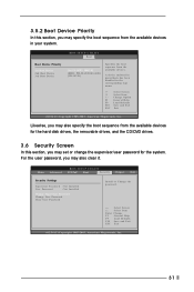
..., American Megatrends, Inc. 3.5.1 Boot Settings Configuration BIOS SETUP UTILITY Boot Boot Settings Configuration Boot From Network Bootup Num-Lock [Disabled] [On] To enable or disable the boot from network feature. +F1 F9 F10 ESC Select Screen Select Item Change Option General Help Load Defaults Save and Exit Exit v02.54 (C) Copyright 1985-2003, American Megatrends, Inc. BIOS SETUP UTILITY Main Advanced PCIPnP Boot Security Chipset Exit Boot Settings Boot Settings Configuration Boot Device Priority Hard Disk Drives Removable Drives CD / DVD Drives Configure Settings during System...
..., American Megatrends, Inc. 3.5.1 Boot Settings Configuration BIOS SETUP UTILITY Boot Boot Settings Configuration Boot From Network Bootup Num-Lock [Disabled] [On] To enable or disable the boot from network feature. +F1 F9 F10 ESC Select Screen Select Item Change Option General Help Load Defaults Save and Exit Exit v02.54 (C) Copyright 1985-2003, American Megatrends, Inc. BIOS SETUP UTILITY Main Advanced PCIPnP Boot Security Chipset Exit Boot Settings Boot Settings Configuration Boot Device Priority Hard Disk Drives Removable Drives CD / DVD Drives Configure Settings during System...
User Manual
Page 31
... UTILITY Main Advanced PCIPnP Boot Security Chipset Exit Security Settings Supervisor Password : Not Installed User Password : Not Installed Change Supervisor Password Change User Password Clear User Password Install or Change the password. A device enclosed in parenthesis has been disabled in your system. Select Screen Select Item Enter Change F1 General Help F9 Load Defaults F10 Save and Exit ESC Exit v02.54 (C) Copyright 1985-2003, American Megatrends, Inc. 31 BIOS SETUP UTILITY Boot Boot Device Priority 1st Boot Device 2nd Boot Device 3rd Boot Device [1st FLOPPY DRIVE] [HDD...
... UTILITY Main Advanced PCIPnP Boot Security Chipset Exit Security Settings Supervisor Password : Not Installed User Password : Not Installed Change Supervisor Password Change User Password Clear User Password Install or Change the password. A device enclosed in parenthesis has been disabled in your system. Select Screen Select Item Enter Change F1 General Help F9 Load Defaults F10 Save and Exit ESC Exit v02.54 (C) Copyright 1985-2003, American Megatrends, Inc. 31 BIOS SETUP UTILITY Boot Boot Device Priority 1st Boot Device 2nd Boot Device 3rd Boot Device [1st FLOPPY DRIVE] [HDD...
User Manual
Page 34
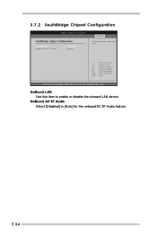
3.7.2 SouthBridge Chipset Configuration BIOS SETUP UTILITY SouthBridge Chipset Configuration Onboard LAN Onboard AC97 Audio [Enabled] [Auto] Chipset Enable / Disable onboard LAN. +F1 F9 F10 ESC Select Screen Select Item Change Option General Help Load Defaults Save and Exit Exit v02.54 (C) Copyright 1985-2003, American Megatrends, Inc. OnBoard AC'97 Audio Select [Disabled] or [Auto] for the onboard AC'97 Audio feature. 34 OnBoard LAN Use this item to enable or disable the onboard LAN device.
3.7.2 SouthBridge Chipset Configuration BIOS SETUP UTILITY SouthBridge Chipset Configuration Onboard LAN Onboard AC97 Audio [Enabled] [Auto] Chipset Enable / Disable onboard LAN. +F1 F9 F10 ESC Select Screen Select Item Change Option General Help Load Defaults Save and Exit Exit v02.54 (C) Copyright 1985-2003, American Megatrends, Inc. OnBoard AC'97 Audio Select [Disabled] or [Auto] for the onboard AC'97 Audio feature. 34 OnBoard LAN Use this item to enable or disable the onboard LAN device.
User Manual
Page 36
... using the support CD, insert the CD into your OS documentation for more information. 4.2 Support CD Information The Support CD that came with the motherboard contains necessary drivers and useful utilities that the motherboard supports. The CD automatically displays the Main Menu if "AUTORUN" is enabled in this demo program, you need to contact ASRock or want to know more about ASRock, welcome to your CD-ROM drive...
... using the support CD, insert the CD into your OS documentation for more information. 4.2 Support CD Information The Support CD that came with the motherboard contains necessary drivers and useful utilities that the motherboard supports. The CD automatically displays the Main Menu if "AUTORUN" is enabled in this demo program, you need to contact ASRock or want to know more about ASRock, welcome to your CD-ROM drive...


