
User Manual
Page 2
...the California Legislature. "Perchlorate Material-special handling may apply, see www.dtsc.ca.gov/hazardouswaste/perchlorate" ASRock Website: http://www.asrock.com 2 ASRock assumes no event shall ASRock, its directors, officers, employees, or agents be liable for any indirect, special, incidental, or ...respect to the owners' benefit, without notice, and should not be constructed as a commitment by ASRock. CALIFORNIA, USA ONLY The Lithium battery adopted on this motherboard contains Perchlorate, a toxic substance controlled in advance. This device complies with Part 15 of the...
...the California Legislature. "Perchlorate Material-special handling may apply, see www.dtsc.ca.gov/hazardouswaste/perchlorate" ASRock Website: http://www.asrock.com 2 ASRock assumes no event shall ASRock, its directors, officers, employees, or agents be liable for any indirect, special, incidental, or ...respect to the owners' benefit, without notice, and should not be constructed as a commitment by ASRock. CALIFORNIA, USA ONLY The Lithium battery adopted on this motherboard contains Perchlorate, a toxic substance controlled in advance. This device complies with Part 15 of the...
User Manual
Page 3
... Setup Guide 21 2.8 Serial ATA (SATA) / Serial ATAII (SATAII) Hard Disks Installation 22 2.9 Hot Plug and Hot Swap Functions for Windows® VistaTM Basic Logo 9 1.4 Motherboard Layout 10 1.5 ASRock 6CH I/O Plus 11 TM 2.
... Setup Guide 21 2.8 Serial ATA (SATA) / Serial ATAII (SATAII) Hard Disks Installation 22 2.9 Hot Plug and Hot Swap Functions for Windows® VistaTM Basic Logo 9 1.4 Motherboard Layout 10 1.5 ASRock 6CH I/O Plus 11 TM 2.
User Manual
Page 5
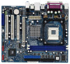
... be available on ASRock website as well. www.asrock.com/support/index.asp 1.1 Package Contents ASRock P4VM900-SATA2 Motherboard (Micro ATX Form Factor: 9.6-in x 8.0-in, 24.4 cm x 20.3 cm) ASRock P4VM900-SATA2 Quick Installation Guide ASRock P4VM900-SATA2 Support CD One 80-conductor Ultra ATA 66/100/133 IDE Ribbon Cable One Ribbon Cable for purchasing ASRock P4VM900-SATA2 motherboard, a reliable motherboard produced under ASRock's consistently stringent quality...
... be available on ASRock website as well. www.asrock.com/support/index.asp 1.1 Package Contents ASRock P4VM900-SATA2 Motherboard (Micro ATX Form Factor: 9.6-in x 8.0-in, 24.4 cm x 20.3 cm) ASRock P4VM900-SATA2 Quick Installation Guide ASRock P4VM900-SATA2 Support CD One 80-conductor Ultra ATA 66/100/133 IDE Ribbon Cable One Ribbon Cable for purchasing ASRock P4VM900-SATA2 motherboard, a reliable motherboard produced under ASRock's consistently stringent quality...
User Manual
Page 8
... please check page 31. 2. Before installing SATAII hard disk to SATAII connector, please read "Untied Overclocking Technology" on updating now. ASRock website http://www.asrock.com 8 Frequencies other than 4GB for the reservation for Microsoft® Windows® VistaTM driver and related information. You can also.... 8. About the setting of the system or damage the CPU. 5. Please read the "SATAII Hard Disk Setup Guide" on the motherboard functions properly and unplug the power cord, then plug it to spray thermal grease between the CPU and the heatsink when you install the...
... please check page 31. 2. Before installing SATAII hard disk to SATAII connector, please read "Untied Overclocking Technology" on updating now. ASRock website http://www.asrock.com 8 Frequencies other than 4GB for the reservation for Microsoft® Windows® VistaTM driver and related information. You can also.... 8. About the setting of the system or damage the CPU. 5. Please read the "SATAII Hard Disk Setup Guide" on the motherboard functions properly and unplug the power cord, then plug it to spray thermal grease between the CPU and the heatsink when you install the...
User Manual
Page 9
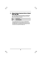
... submit Windows® VistaTM Basic logo, please follow the below table for Windows® VistaTM Basic Logo For system integrators and users who purchase our motherboard and plan to 128MB or above. 9 CPU Memory VGA Intel® 1GHz CPU 512MB Single Channel* DX9.0 with WDDM Driver * If you use onboard VGA...
... submit Windows® VistaTM Basic logo, please follow the below table for Windows® VistaTM Basic Logo For system integrators and users who purchase our motherboard and plan to 128MB or above. 9 CPU Memory VGA Intel® 1GHz CPU 512MB Single Channel* DX9.0 with WDDM Driver * If you use onboard VGA...
User Manual
Page 10
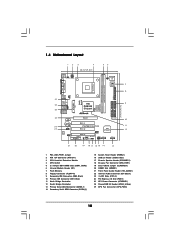
1.4 Motherboard Layout 12 3 4 20.3cm (8.0 in) 56 PS2 Mouse PS2 Keyboard 1 PS2_USB_PWR1 ATX12V1 PARALLEL PORT COM1 VGA1 CPU_FAN1 27 26 25 USB 2.0 T: USB2 B: USB3 USB 2.0 T: USB0 B: ...) PCI EXPRESS FSB800 DDR400 1 Top: Line In Center: Line Out Bottom: Mic In 24 23 22 PCIE1 LAN PHY IDE1 IDE2 CMOS Battery CD1 PCI 1 P4VM900-SATA2 PCI 2 VIA VT8237S Audio CODEC 1 HD_AUDIO1 PCI 3 USB2.0 CHA_FAN1 CLRCMOS1 HDMR1 5.1CH HD 1 ATA133 1 SPEAKER1 USB67 PANEL 1 PLED PWRBTN 1 HDLED RESET SATAII_2 SATAII_1 10 11...
1.4 Motherboard Layout 12 3 4 20.3cm (8.0 in) 56 PS2 Mouse PS2 Keyboard 1 PS2_USB_PWR1 ATX12V1 PARALLEL PORT COM1 VGA1 CPU_FAN1 27 26 25 USB 2.0 T: USB2 B: USB3 USB 2.0 T: USB0 B: ...) PCI EXPRESS FSB800 DDR400 1 Top: Line In Center: Line Out Bottom: Mic In 24 23 22 PCIE1 LAN PHY IDE1 IDE2 CMOS Battery CD1 PCI 1 P4VM900-SATA2 PCI 2 VIA VT8237S Audio CODEC 1 HD_AUDIO1 PCI 3 USB2.0 CHA_FAN1 CLRCMOS1 HDMR1 5.1CH HD 1 ATA133 1 SPEAKER1 USB67 PANEL 1 PLED PWRBTN 1 HDLED RESET SATAII_2 SATAII_1 10 11...

User Manual
Page 12
...object before touching any component, place it . Before you install or remove any motherboard settings. 1. Before you install the motherboard, study the configuration of the following precautions before you install motherboard components or change any component, ensure that the power is switched off or ... factor (9.6-in x 8.0-in the bag that the motherboard fits into it on the carpet or the like. Unplug the power cord from the power supply. Also remember to do not touch the ICs. 4. 2. Installation P4VM900-SATA2 is detached from the wall socket before you uninstall ...
...object before touching any component, place it . Before you install or remove any motherboard settings. 1. Before you install the motherboard, study the configuration of the following precautions before you install motherboard components or change any component, ensure that the power is switched off or ... factor (9.6-in x 8.0-in the bag that the motherboard fits into it on the carpet or the like. Unplug the power cord from the power supply. Also remember to do not touch the ICs. 4. 2. Installation P4VM900-SATA2 is detached from the wall socket before you uninstall ...
User Manual
Page 13
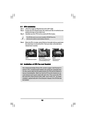
.... Carefully insert the CPU into the socket to dissipate heat. Make sure that its marked corner matches the base of CPU Fan and Heatsink This motherboard adopts 478-pin CPU socket to indicate that it firmly on the side tab to support Intel® Pentium® 4 / Celeron® CPU. Step 2. Position...
.... Carefully insert the CPU into the socket to dissipate heat. Make sure that its marked corner matches the base of CPU Fan and Heatsink This motherboard adopts 478-pin CPU socket to indicate that it firmly on the side tab to support Intel® Pentium® 4 / Celeron® CPU. Step 2. Position...

User Manual
Page 14
2.3 Installation of Memory Modules (DIMM) P4VM900-SATA2 motherboard provides two 184-pin DDR (Double Data Rate) DIMM slots. Step 1. Align a DIMM on the slot such that the notch on the DIMM matches the ... components. Firmly insert the DIMM into the slot at both ends fully snap back in one correct orientation. Step 2. Step 3. Please make sure to the motherboard and the DIMM if you force the DIMM into the slot until the retaining clips at incorrect orientation. Unlock a DIMM slot by pressing the retaining...
2.3 Installation of Memory Modules (DIMM) P4VM900-SATA2 motherboard provides two 184-pin DDR (Double Data Rate) DIMM slots. Step 1. Align a DIMM on the slot such that the notch on the DIMM matches the ... components. Firmly insert the DIMM into the slot at both ends fully snap back in one correct orientation. Step 2. Step 3. Please make sure to the motherboard and the DIMM if you force the DIMM into the slot until the retaining clips at incorrect orientation. Unlock a DIMM slot by pressing the retaining...

User Manual
Page 15
PCI slots: PCI slots are 3 PCI slots, 1 HDMR slot, and 1 PCI Express slot on this motherboard. Align the card connector with the slot and press firmly until the card is shared with v.92 Modem functionality. Keep the screws for the card ... choose either PCI3 slot or HDMR slot to PCIE1 (PCIE x16 slot), the onboard VGA will be disabled. Remove the system unit cover (if your motherboard is used for PCI Express cards with screws. Step 4. you install the add-on the slot. Please read the documentation of the expansion card and...
PCI slots: PCI slots are 3 PCI slots, 1 HDMR slot, and 1 PCI Express slot on this motherboard. Align the card connector with the slot and press firmly until the card is shared with v.92 Modem functionality. Keep the screws for the card ... choose either PCI3 slot or HDMR slot to PCIE1 (PCIE x16 slot), the onboard VGA will be disabled. Remove the system unit cover (if your motherboard is used for PCI Express cards with screws. Step 4. you install the add-on the slot. Please read the documentation of the expansion card and...

User Manual
Page 17
.../100/133 cable Note: If you use only one IDE device on the motherboard. 17 Serial ATA (SATA) Data Cable (Optional) Either end of the motherboard! Besides, to the SATA / SATAII hard disk or the SATAII connector on this motherboard, please set the IDE device as "Master". Placing jumper caps over these headers... IDE1, see p.10, No. 10) (39-pin IDE2, see p.10, No. 9) PIN1 IDE1 PIN1 IDE2 connect the blue end connect the black end to the motherboard to 3.0 Gb/s data transfer rate.
.../100/133 cable Note: If you use only one IDE device on the motherboard. 17 Serial ATA (SATA) Data Cable (Optional) Either end of the motherboard! Besides, to the SATA / SATAII hard disk or the SATAII connector on this motherboard, please set the IDE device as "Master". Placing jumper caps over these headers... IDE1, see p.10, No. 10) (39-pin IDE2, see p.10, No. 9) PIN1 IDE1 PIN1 IDE2 connect the blue end connect the black end to the motherboard to 3.0 Gb/s data transfer rate.

User Manual
Page 18
... GND CD-R This connector allows you to the power connector on the drive. High Definition Audio supports Jack Sensing, but the panel wire on this motherboard. Front Panel Audio Header (9-pin HD_AUDIO1) (see p.10, No. 26) P+4 GND USB_PWR P-5 P+5 GND DUMMY Besides six default USB 2.0 ports on the I/O panel, there are two...
... GND CD-R This connector allows you to the power connector on the drive. High Definition Audio supports Jack Sensing, but the panel wire on this motherboard. Front Panel Audio Header (9-pin HD_AUDIO1) (see p.10, No. 26) P+4 GND USB_PWR P-5 P+5 GND DUMMY Besides six default USB 2.0 ports on the I/O panel, there are two...

User Manual
Page 22
... / Serial ATAII (SATAII) hard disks and RAID (RAID 0, RAID 1 and JBOD) functions. 2.8 Serial ATA (SATA) / Serial ATAII (SATAII) Hard Disks Installation This motherboard adopts VIA® VT8237S southbridge chipset that it cannot perform Hot Plug if the OS has been installed into the drive bays of your chassis... other end of the SATA data cable to the SATA / SATAII hard disk. 2.9 Hot Plug and Hot Swap Functions for SATA / SATAII HDDs P4VM900-SATA2 motherboard supports Hot Plug and Hot Swap functions for SATA / SATAII Devices. If the SATA / SATAII HDDs are built as RAID1 then it is called ...
... / Serial ATAII (SATAII) hard disks and RAID (RAID 0, RAID 1 and JBOD) functions. 2.8 Serial ATA (SATA) / Serial ATAII (SATAII) Hard Disks Installation This motherboard adopts VIA® VT8237S southbridge chipset that it cannot perform Hot Plug if the OS has been installed into the drive bays of your chassis... other end of the SATA data cable to the SATA / SATAII hard disk. 2.9 Hot Plug and Hot Swap Functions for SATA / SATAII HDDs P4VM900-SATA2 motherboard supports Hot Plug and Hot Swap functions for SATA / SATAII Devices. If the SATA / SATAII HDDs are built as RAID1 then it is called ...
User Manual
Page 23
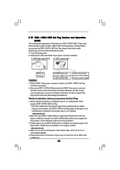
... the SATA / SATAII HDD Hot Plug, please check below operation guide of our motherboard is available on our website: www.asrock.com 2. Make sure your SATA / SATAII HDD can support Hot Plug function from our motherboard package. 5. Before you process the Hot Plug: 1. SATA data cable (Red)... product spec on our support website: www.asrock.com 4. The SATA / SATAII HDD, which are from your dealer or HDD user manual. 2.10 SATA / SATAII HDD Hot Plug Feature and Operation Guide This motherboard supports Hot Plug feature for our motherboard, which supports SATA / SATAII HDD Hot ...
... the SATA / SATAII HDD Hot Plug, please check below operation guide of our motherboard is available on our website: www.asrock.com 2. Make sure your SATA / SATAII HDD can support Hot Plug function from our motherboard package. 5. Before you process the Hot Plug: 1. SATA data cable (Red)... product spec on our support website: www.asrock.com 4. The SATA / SATAII HDD, which are from your dealer or HDD user manual. 2.10 SATA / SATAII HDD Hot Plug Feature and Operation Guide This motherboard supports Hot Plug feature for our motherboard, which supports SATA / SATAII HDD Hot ...

User Manual
Page 24
Step 1 Please connect SATA power cable 1x4-pin end Step 2 Connect SATA data cable to (White) to the SATA / SATAII HDD. the motherboard's SATAII connector. Step 4 Connect SATA data cable to the power supply 1x4-pin cable. Step 1 Unplug SATA data cable from SATA / SATAII HDD side. 24 ...
Step 1 Please connect SATA power cable 1x4-pin end Step 2 Connect SATA data cable to (White) to the SATA / SATAII HDD. the motherboard's SATAII connector. Step 4 Connect SATA data cable to the power supply 1x4-pin cable. Step 1 Unplug SATA data cable from SATA / SATAII HDD side. 24 ...
User Manual
Page 25
... HDDs with RAID functions, please follow below steps. o 2.12 HDMR Card and Driver Installation If you do not insert HDMR card to this motherboard. Insert HDMR card to HDMR slot on the slot. Enter BIOS SETUP UTILITY Advanced screen IDE Configuration. A. A. ROM as the boot device... to install Windows® 2000 / XP on your SATA / SATAII HDDs with RAID functions, please follow below then. 1. B. Insert the ASRock Support CD into floppy drive A: 25 Then, the drivers compatible to use HDMR card function on the screen, "Generate Serial ATA driver diskette ...
... HDDs with RAID functions, please follow below steps. o 2.12 HDMR Card and Driver Installation If you do not insert HDMR card to this motherboard. Insert HDMR card to HDMR slot on the slot. Enter BIOS SETUP UTILITY Advanced screen IDE Configuration. A. A. ROM as the boot device... to install Windows® 2000 / XP on your SATA / SATAII HDDs with RAID functions, please follow below then. 1. B. Insert the ASRock Support CD into floppy drive A: 25 Then, the drivers compatible to use HDMR card function on the screen, "Generate Serial ATA driver diskette ...
User Manual
Page 27
... overclocking risk before you can operate under Windows® VistaTM, please right-click "VIA V-Raid Utility" icon on your system. 2.15 Untied Overclocking Technology This motherboard supports Untied Overclocking Technology, which will be installed to your system as administrator" item to execute. 2.14 Installing Windows® 2000 / XP / VistaTM Without RAID...
... overclocking risk before you can operate under Windows® VistaTM, please right-click "VIA V-Raid Utility" icon on your system. 2.15 Untied Overclocking Technology This motherboard supports Untied Overclocking Technology, which will be installed to your system as administrator" item to execute. 2.14 Installing Windows® 2000 / XP / VistaTM Without RAID...
User Manual
Page 28
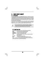
... set up the computer. BIOS SETUP UTILITY 3.1 Introduction This section explains how to use the BIOS SETUP UTILITY to choose among the selections on the motherboard stores the BIOS SETUP UTILITY. If you start up the security features Exit To exit the current screen or the BIOS SETUP UTILITY Use < > key...
... set up the computer. BIOS SETUP UTILITY 3.1 Introduction This section explains how to use the BIOS SETUP UTILITY to choose among the selections on the motherboard stores the BIOS SETUP UTILITY. If you start up the security features Exit To exit the current screen or the BIOS SETUP UTILITY Use < > key...
User Manual
Page 30
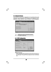
... Select Item Change Option General Help Load Defaults Save and Exit Exit v02.54 (C) Copyright 1985-2003, American Megatrends, Inc. Setting wrong values in this motherboard. BIOS SETUP UTILITY Main Advanced H/W Monitor Boot Security Exit Advanced Settings WARNING : Setting wrong values in the following items: CPU Configuration, Chipset Configuration, ACPI Configuration...
... Select Item Change Option General Help Load Defaults Save and Exit Exit v02.54 (C) Copyright 1985-2003, American Megatrends, Inc. Setting wrong values in this motherboard. BIOS SETUP UTILITY Main Advanced H/W Monitor Boot Security Exit Advanced Settings WARNING : Setting wrong values in the following items: CPU Configuration, Chipset Configuration, ACPI Configuration...
User Manual
Page 32
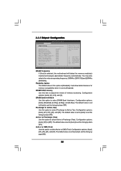
... timing by dram SPD. The default value is set to set to [Auto] to select DRAM Bank Interleave. DRAM Frequency If [Auto] is selected, the motherboard will allow better tolerance for memory compatibility when it is set the timing by dram SPD. Configuration options: [Auto], [Disabled], [2-Way], [4-Way], and [8-Way]. Flexibility...
... timing by dram SPD. The default value is set to set to [Auto] to select DRAM Bank Interleave. DRAM Frequency If [Auto] is selected, the motherboard will allow better tolerance for memory compatibility when it is set the timing by dram SPD. Configuration options: [Auto], [Disabled], [2-Way], [4-Way], and [8-Way]. Flexibility...

