User Manual
Page 1
All rights reserved. 1 P4VM900-SATA2 User Manual Version 1.0 Published August 2007 Copyright©2007 ASRock INC.
All rights reserved. 1 P4VM900-SATA2 User Manual Version 1.0 Published August 2007 Copyright©2007 ASRock INC.

User Manual
Page 2
... Material-special handling may not cause harmful interference, and (2) this device must accept any defect or error in this manual, ASRock does not provide warranty of any means, except duplication of documentation by any kind, either expressed or implied, including ...: (1) this device may apply, see www.dtsc.ca.gov/hazardouswaste/perchlorate" ASRock Website: http://www.asrock.com 2 Copyright Notice: No part of this manual. CALIFORNIA, USA ONLY The Lithium battery adopted on this manual may or may not be registered trademarks or copyrights of their respective companies, ...
... Material-special handling may not cause harmful interference, and (2) this device must accept any defect or error in this manual, ASRock does not provide warranty of any means, except duplication of documentation by any kind, either expressed or implied, including ...: (1) this device may apply, see www.dtsc.ca.gov/hazardouswaste/perchlorate" ASRock Website: http://www.asrock.com 2 Copyright Notice: No part of this manual. CALIFORNIA, USA ONLY The Lithium battery adopted on this manual may or may not be registered trademarks or copyrights of their respective companies, ...
User Manual
Page 5
... the hardware installation. Because the motherboard specifications and the BIOS software might be updated, the content of this manual will be subject to change without further notice. www.asrock.com/support/index.asp 1.1 Package Contents ASRock P4VM900-SATA2 Motherboard (Micro ATX Form Factor: 9.6-in x 8.0-in Floppy Drive One Serial ATA (SATA) Cable (Optional) One Serial...
... the hardware installation. Because the motherboard specifications and the BIOS software might be updated, the content of this manual will be subject to change without further notice. www.asrock.com/support/index.asp 1.1 Package Contents ASRock P4VM900-SATA2 Motherboard (Micro ATX Form Factor: 9.6-in x 8.0-in Floppy Drive One Serial ATA (SATA) Cable (Optional) One Serial...
User Manual
Page 13
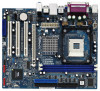
... firmly on the side tab to indicate that its marked corner matches the base of the pins. Then connect the CPU fan to the instruction manuals of CPU Fan and Heatsink This motherboard adopts 478-pin CPU socket to secure the CPU. The lever clicks on the socket while you push...
... firmly on the side tab to indicate that its marked corner matches the base of the pins. Then connect the CPU fan to the instruction manuals of CPU Fan and Heatsink This motherboard adopts 478-pin CPU socket to secure the CPU. The lever clicks on the socket while you push...

User Manual
Page 18
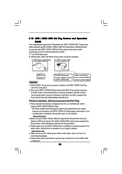
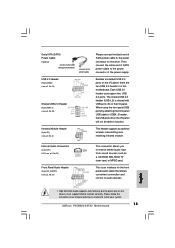
... audio input CD1 from sound sources such as a CD-ROM, DVD-ROM, TV tuner card, or MPEG card. Please follow the instruction in our manual and chassis manual to the power connector of the power supply. Each USB 2.0 header can support two USB 2.0 ports. Internal Audio Connectors (4-pin CD1) (CD1: see p.10...
... audio input CD1 from sound sources such as a CD-ROM, DVD-ROM, TV tuner card, or MPEG card. Please follow the instruction in our manual and chassis manual to the power connector of the power supply. Each USB 2.0 header can support two USB 2.0 ports. Internal Audio Connectors (4-pin CD1) (CD1: see p.10...
User Manual
Page 23
...SATAII HDD. Please make sure the SATA / SATAII driver is indicated in the product spec on our support website: www.asrock.com 4. Make sure your dealer or HDD user manual. SATA power cable with SATA 15-pin power connector interface A. SATA data cable (Red) B. Without SATA 15-pin ...power connector and IDE 1x4-pin conventional power connector interfaces, the IDE 1x4-pin conventional power connector interface is available on our website: www.asrock.com 2. The latest SATA / SATAII driver is definitely not able to use the SATA power cable & data cable, which cannot support Hot...
...SATAII HDD. Please make sure the SATA / SATAII driver is indicated in the product spec on our support website: www.asrock.com 4. Make sure your dealer or HDD user manual. SATA power cable with SATA 15-pin power connector interface A. SATA data cable (Red) B. Without SATA 15-pin ...power connector and IDE 1x4-pin conventional power connector interfaces, the IDE 1x4-pin conventional power connector interface is available on our website: www.asrock.com 2. The latest SATA / SATAII driver is definitely not able to use the SATA power cable & data cable, which cannot support Hot...

Quick Installation Guide
Page 4
... and the BIOS software might be updated, the content of this manual will be found in the user manual presented in Floppy Drive One Serial ATA (SATA) Cable (Optional) One Serial ATA (SATA) HDD Power Cable (Optional) One ASRock 6CH I/O PlusTM Shield 4 ASRock P4VM900-SATA2 Motherboard English You may find the latest VGA cards and CPU...
... and the BIOS software might be updated, the content of this manual will be found in the user manual presented in Floppy Drive One Serial ATA (SATA) Cable (Optional) One Serial ATA (SATA) HDD Power Cable (Optional) One ASRock 6CH I/O PlusTM Shield 4 ASRock P4VM900-SATA2 Motherboard English You may find the latest VGA cards and CPU...
Quick Installation Guide
Page 7
... the chipset limitation, the actual memory size may be less than the recommended CPU bus frequencies may cause the instability of "User Manual" in the future. ASRock website http://www.asrock.com 7 ASRock P4VM900-SATA2 Motherboard English As long as we have the latest driver, we will automatically shutdown. Please visit our website for system usage...
... the chipset limitation, the actual memory size may be less than the recommended CPU bus frequencies may cause the instability of "User Manual" in the future. ASRock website http://www.asrock.com 7 ASRock P4VM900-SATA2 Motherboard English As long as we have the latest driver, we will automatically shutdown. Please visit our website for system usage...
Quick Installation Guide
Page 10
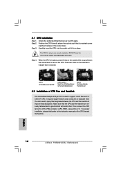
...lever. Then connect the CPU fan to a 90° angle. 2.1 CPU Installation Step 1. Carefully insert the CPU into the socket to the instruction manuals of the pins. Unlock the socket by lifting the lever up to the CPU_FAN connector (CPU_FAN1, see p.2 No. 27). You also need to spray... and the heatsink to dissipate heat. For proper installation, please kindly refer to avoid bending of the CPU fan and the heatsink. English 10 ASRock P4VM900-SATA2 Motherboard Lift Lever Up to 90° CPU Marked Corner Socket Marked Corner STEP 1: Lift The Socket Lever Up to 90° STEP 2/...
...lever. Then connect the CPU fan to a 90° angle. 2.1 CPU Installation Step 1. Carefully insert the CPU into the socket to the instruction manuals of the pins. Unlock the socket by lifting the lever up to the CPU_FAN connector (CPU_FAN1, see p.2 No. 27). You also need to spray... and the heatsink to dissipate heat. For proper installation, please kindly refer to avoid bending of the CPU fan and the heatsink. English 10 ASRock P4VM900-SATA2 Motherboard Lift Lever Up to 90° CPU Marked Corner Socket Marked Corner STEP 1: Lift The Socket Lever Up to 90° STEP 2/...
Quick Installation Guide
Page 15
... audio devices. This is shared with USB ports 45 on this motherboard. Please follow the instruction in our manual and chassis manual to the power connector of SATA power cable to install your system. 15 ASRock P4VM900-SATA2 Motherboard Each USB 2.0 header can support two USB 2.0 ports. This header supports an optional wireless transmitting and...
... audio devices. This is shared with USB ports 45 on this motherboard. Please follow the instruction in our manual and chassis manual to the power connector of SATA power cable to install your system. 15 ASRock P4VM900-SATA2 Motherboard Each USB 2.0 header can support two USB 2.0 ports. This header supports an optional wireless transmitting and...
Quick Installation Guide
Page 23
It is a menu-driven program, which allows you to scroll through its test routines. When you wish to the User Manual (PDF file) contained in your CD-ROM drive. It will enhance motherboard features. For the detailed information about BIOS Setup, please refer to enter BIOS ... and to be user-friendly. If you start up the computer, please press during the Power-On-Self-Test (POST) to display the menus. 23 ASRock P4VM900-SATA2 Motherboard English BIOS Information The Flash Memory on the file "ASSETUP.EXE" from the BIN folder in the Support CD to enter BIOS Setup utility...
It is a menu-driven program, which allows you to scroll through its test routines. When you wish to the User Manual (PDF file) contained in your CD-ROM drive. It will enhance motherboard features. For the detailed information about BIOS Setup, please refer to enter BIOS ... and to be user-friendly. If you start up the computer, please press during the Power-On-Self-Test (POST) to display the menus. 23 ASRock P4VM900-SATA2 Motherboard English BIOS Information The Flash Memory on the file "ASSETUP.EXE" from the BIN folder in the Support CD to enter BIOS Setup utility...

RAID Installation Guide
Page 7
... is selected in step 2, user can be selected from 4K to select them respectively. There are two methods to let user select the array drives manually. Use the arrow key to highlight the "Block Size" and press .
... is selected in step 2, user can be selected from 4K to select them respectively. There are two methods to let user select the array drives manually. Use the arrow key to highlight the "Block Size" and press .

RAID Installation Guide
Page 20
... select array disks for this array will be limited on this step. Select Array Disks 20 Besides, you have to select disks for the array manually. As soon as you select one type by clicking corresponding item and click . Select Controller and Creating Method Select a controller to create array. Selecting "Custom... all available disks in the available disks list, and you have to select the creation method in both cases. You may adjust the selected disks manually in this controller. B. C.
... select array disks for this array will be limited on this step. Select Array Disks 20 Besides, you have to select disks for the array manually. As soon as you select one type by clicking corresponding item and click . Select Controller and Creating Method Select a controller to create array. Selecting "Custom... all available disks in the available disks list, and you have to select the creation method in both cases. You may adjust the selected disks manually in this controller. B. C.
