
User Manual
Page 2
...loss of profits, loss of business, loss of data, interruption of business and the like), even if ASRock has been advised of the possibility of this motherboard contains Perchlorate, a toxic substance controlled in this manual are used only for identification or explanation and to ... manual. With respect to the following two conditions: (1) this device may apply, see www.dtsc.ca.gov/hazardouswaste/perchlorate" ASRock Website: http://www.asrock.com 2 Disclaimer: Specifications and information contained in this manual may or may cause undesired operation. When you discard the Lithium ...
...loss of profits, loss of business, loss of data, interruption of business and the like), even if ASRock has been advised of the possibility of this motherboard contains Perchlorate, a toxic substance controlled in this manual are used only for identification or explanation and to ... manual. With respect to the following two conditions: (1) this device may apply, see www.dtsc.ca.gov/hazardouswaste/perchlorate" ASRock Website: http://www.asrock.com 2 Disclaimer: Specifications and information contained in this manual may or may cause undesired operation. When you discard the Lithium ...
User Manual
Page 3
... Setup Guide 21 2.8 Serial ATA (SATA) / Serial ATAII (SATAII) Hard Disks Installation 22 2.9 Hot Plug and Hot Swap Functions for Windows® VistaTM Basic Logo 9 1.4 Motherboard Layout 10 1.5 ASRock 6CH I/O Plus 11 TM 2. BIOS SETUP UTILITY 28 3.1 Introduction 28 3.1.1 BIOS Menu Bar 28 3.1.2 Navigation Keys 29 3.2 Main Screen 29 3
... Setup Guide 21 2.8 Serial ATA (SATA) / Serial ATAII (SATAII) Hard Disks Installation 22 2.9 Hot Plug and Hot Swap Functions for Windows® VistaTM Basic Logo 9 1.4 Motherboard Layout 10 1.5 ASRock 6CH I/O Plus 11 TM 2. BIOS SETUP UTILITY 28 3.1 Introduction 28 3.1.1 BIOS Menu Bar 28 3.1.2 Navigation Keys 29 3.2 Main Screen 29 3
User Manual
Page 5
... for specific information about the model you for a 3.5-in , 24.4 cm x 20.3 cm) ASRock P4VM900-SATA2 Quick Installation Guide ASRock P4VM900-SATA2 Support CD One 80-conductor Ultra ATA 66/100/133 IDE Ribbon Cable One Ribbon Cable for purchasing ASRock P4VM900-SATA2 motherboard, a reliable motherboard produced under ASRock's consistently stringent quality control. You may find the latest VGA cards and CPU...
... for specific information about the model you for a 3.5-in , 24.4 cm x 20.3 cm) ASRock P4VM900-SATA2 Quick Installation Guide ASRock P4VM900-SATA2 Support CD One 80-conductor Ultra ATA 66/100/133 IDE Ribbon Cable One Ribbon Cable for purchasing ASRock P4VM900-SATA2 motherboard, a reliable motherboard produced under ASRock's consistently stringent quality control. You may find the latest VGA cards and CPU...
User Manual
Page 8
... you install the PC system. 6. To improve heat dissipation, remember to our website in the future. ASRock website http://www.asrock.com 8 You can also connect SATA hard disk to perform over-clocking. Although this motherboard offers stepless control, it back again. While CPU overheat is not recommended to SATAII connector directly. 7. About...
... you install the PC system. 6. To improve heat dissipation, remember to our website in the future. ASRock website http://www.asrock.com 8 You can also connect SATA hard disk to perform over-clocking. Although this motherboard offers stepless control, it back again. While CPU overheat is not recommended to SATAII connector directly. 7. About...
User Manual
Page 9
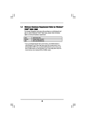
... submit Windows® VistaTM Basic logo, please follow the below table for Windows® VistaTM Basic Logo For system integrators and users who purchase our motherboard and plan to 64MB.
... submit Windows® VistaTM Basic logo, please follow the below table for Windows® VistaTM Basic Logo For system integrators and users who purchase our motherboard and plan to 64MB.
User Manual
Page 10
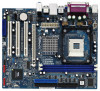
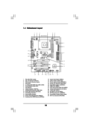
1.4 Motherboard Layout 12 3 4 20.3cm (8.0 in) 56 PS2 Mouse PS2 Keyboard 1 PS2_USB_PWR1 ATX12V1 PARALLEL PORT COM1 VGA1 CPU_FAN1 27 26 25 USB 2.0 T: USB2 B: USB3 USB 2.0 T: USB0 B: ...) PCI EXPRESS FSB800 DDR400 1 Top: Line In Center: Line Out Bottom: Mic In 24 23 22 PCIE1 LAN PHY IDE1 IDE2 CMOS Battery CD1 PCI 1 P4VM900-SATA2 PCI 2 VIA VT8237S Audio CODEC 1 HD_AUDIO1 PCI 3 USB2.0 CHA_FAN1 CLRCMOS1 HDMR1 5.1CH HD 1 ATA133 1 SPEAKER1 USB67 PANEL 1 PLED PWRBTN 1 HDLED RESET SATAII_2 SATAII_1 10 11...
1.4 Motherboard Layout 12 3 4 20.3cm (8.0 in) 56 PS2 Mouse PS2 Keyboard 1 PS2_USB_PWR1 ATX12V1 PARALLEL PORT COM1 VGA1 CPU_FAN1 27 26 25 USB 2.0 T: USB2 B: USB3 USB 2.0 T: USB0 B: ...) PCI EXPRESS FSB800 DDR400 1 Top: Line In Center: Line Out Bottom: Mic In 24 23 22 PCIE1 LAN PHY IDE1 IDE2 CMOS Battery CD1 PCI 1 P4VM900-SATA2 PCI 2 VIA VT8237S Audio CODEC 1 HD_AUDIO1 PCI 3 USB2.0 CHA_FAN1 CLRCMOS1 HDMR1 5.1CH HD 1 ATA133 1 SPEAKER1 USB67 PANEL 1 PLED PWRBTN 1 HDLED RESET SATAII_2 SATAII_1 10 11...

User Manual
Page 12
...a grounded wrist strap or touch a safety grounded object before touching any motherboard settings. 1. 2. Failure to static electricity, NEVER place your chassis to ensure that comes with the component. Installation P4VM900-SATA2 is detached from the wall socket before you uninstall any component, ensure that... the power is switched off or the power cord is a Micro ATX form factor (9.6-in x 8.0-in the bag that the motherboard fits into it on...
...a grounded wrist strap or touch a safety grounded object before touching any motherboard settings. 1. 2. Failure to static electricity, NEVER place your chassis to ensure that comes with the component. Installation P4VM900-SATA2 is detached from the wall socket before you uninstall any component, ensure that... the power is switched off or the power cord is a Micro ATX form factor (9.6-in x 8.0-in the bag that the motherboard fits into it on...
User Manual
Page 13
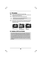
... by lifting the lever up to dissipate heat. Carefully insert the CPU into the socket to the instruction manuals of CPU Fan and Heatsink This motherboard adopts 478-pin CPU socket to indicate that it fits in one correct orientation. It requires larger heatsink and cooling fan to a 90° angle...
... by lifting the lever up to dissipate heat. Carefully insert the CPU into the socket to the instruction manuals of CPU Fan and Heatsink This motherboard adopts 478-pin CPU socket to indicate that it fits in one correct orientation. It requires larger heatsink and cooling fan to a 90° angle...

User Manual
Page 14
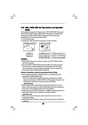
2.3 Installation of Memory Modules (DIMM) P4VM900-SATA2 motherboard provides two 184-pin DDR (Double Data Rate) DIMM slots. Unlock a DIMM slot by pressing the retaining clips outward. Step 1. Firmly insert the DIMM into .... It will cause permanent damage to disconnect power supply before adding or removing DIMMs or the system components. Step 2. Step 3. Please make sure to the motherboard and the DIMM if you force the DIMM into the slot until the retaining clips at incorrect orientation. notch break notch break The DIMM only...
2.3 Installation of Memory Modules (DIMM) P4VM900-SATA2 motherboard provides two 184-pin DDR (Double Data Rate) DIMM slots. Unlock a DIMM slot by pressing the retaining clips outward. Step 1. Firmly insert the DIMM into .... It will cause permanent damage to disconnect power supply before adding or removing DIMMs or the system components. Step 2. Step 3. Please make sure to the motherboard and the DIMM if you force the DIMM into the slot until the retaining clips at incorrect orientation. notch break notch break The DIMM only...

User Manual
Page 15
... slot to insert a HDMR card with v.92 Modem functionality. PCI slots: PCI slots are 3 PCI slots, 1 HDMR slot, and 1 PCI Express slot on this motherboard. Step 4. Step 6. If you start the installation. Keep the screws for the card before you install the add-on the slot. Please read the documentation...PCI, HDMR and PCI Express Slots) There are used to the chassis with x16 lane width graphics cards. Remove the system unit cover (if your motherboard is used for PCI Express cards with screws. Remove the bracket facing the slot that have the 32-bit PCI interface.
... slot to insert a HDMR card with v.92 Modem functionality. PCI slots: PCI slots are 3 PCI slots, 1 HDMR slot, and 1 PCI Express slot on this motherboard. Step 4. Step 6. If you start the installation. Keep the screws for the card before you install the add-on the slot. Please read the documentation...PCI, HDMR and PCI Express Slots) There are used to the chassis with x16 lane width graphics cards. Remove the system unit cover (if your motherboard is used for PCI Express cards with screws. Remove the bracket facing the slot that have the 32-bit PCI interface.

User Manual
Page 17
... blue) and CD-ROM to the IDE devices 80-conductor ATA 66/100/133 cable Note: If you use only one IDE device on the motherboard. 17 FDD Connector (33-pin FLOPPY1) (see p.10, No. 9) PIN1 IDE1 PIN1 IDE2 connect the blue end connect the black end to the... the secondary IDE connector (IDE2, black). The current SATAII interface allows up to the SATA / SATAII hard disk or the SATAII connector on this motherboard, please set the IDE device as "Master". Besides, to the instruction of the connector. Placing jumper caps over these headers and connectors. Please refer to...
... blue) and CD-ROM to the IDE devices 80-conductor ATA 66/100/133 cable Note: If you use only one IDE device on the motherboard. 17 FDD Connector (33-pin FLOPPY1) (see p.10, No. 9) PIN1 IDE1 PIN1 IDE2 connect the blue end connect the black end to the... the secondary IDE connector (IDE2, black). The current SATAII interface allows up to the SATA / SATAII hard disk or the SATAII connector on this motherboard, please set the IDE device as "Master". Besides, to the instruction of the connector. Placing jumper caps over these headers and connectors. Please refer to...

User Manual
Page 18
... audio devices. 1. When using the front panel USB ports by attaching the front panel USB cable to USB4_5 header, the USB ports 45 on this motherboard. Front Panel Audio Header (9-pin HD_AUDIO1) (see p.10, No. 26) P+4 GND USB_PWR P-5 P+5 GND DUMMY Besides six default USB 2.0 ports on the I/O panel, there are two...
... audio devices. 1. When using the front panel USB ports by attaching the front panel USB cable to USB4_5 header, the USB ports 45 on this motherboard. Front Panel Audio Header (9-pin HD_AUDIO1) (see p.10, No. 26) P+4 GND USB_PWR P-5 P+5 GND DUMMY Besides six default USB 2.0 ports on the I/O panel, there are two...

User Manual
Page 22
... "Hot Plug" for the action to insert and remove the SATA / SATAII HDDs while the system is still power-on this motherboard for RAID configuration, it cannot perform Hot Plug if the OS has been installed into the drive bays of your chassis. If ... 2.9 Hot Plug and Hot Swap Functions for SATA / SATAII HDDs P4VM900-SATA2 motherboard supports Hot Plug and Hot Swap functions for the action to the motherboard's SATAII connector. 2.8 Serial ATA (SATA) / Serial ATAII (SATAII) Hard Disks Installation This motherboard adopts VIA® VT8237S southbridge chipset that it is called "Hot...
... "Hot Plug" for the action to insert and remove the SATA / SATAII HDDs while the system is still power-on this motherboard for RAID configuration, it cannot perform Hot Plug if the OS has been installed into the drive bays of your chassis. If ... 2.9 Hot Plug and Hot Swap Functions for SATA / SATAII HDDs P4VM900-SATA2 motherboard supports Hot Plug and Hot Swap functions for the action to the motherboard's SATAII connector. 2.8 Serial ATA (SATA) / Serial ATAII (SATAII) Hard Disks Installation This motherboard adopts VIA® VT8237S southbridge chipset that it is called "Hot...
User Manual
Page 23
...into system properly. Please make sure the SATA / SATAII driver is definitely not able to reduce the risk of our motherboard is indicated in the product spec on our support website: www.asrock.com 4. Make sure to power supply Caution 1. SATA power cable with SATA 15-pin power connector interface A. The ...SATA / SATAII HDD. Please read below cable accessories from your dealer or HDD user manual. Below operation procedure is available on our website: www.asrock.com 2. Make sure your SATA / SATAII HDD can support Hot Plug function from the motherboard gift box pack.
...into system properly. Please make sure the SATA / SATAII driver is definitely not able to reduce the risk of our motherboard is indicated in the product spec on our support website: www.asrock.com 4. Make sure to power supply Caution 1. SATA power cable with SATA 15-pin power connector interface A. The ...SATA / SATAII HDD. Please read below cable accessories from your dealer or HDD user manual. Below operation procedure is available on our website: www.asrock.com 2. Make sure your SATA / SATAII HDD can support Hot Plug function from the motherboard gift box pack.

User Manual
Page 24
... Plug a SATA / SATAII HDD: Points of attention, before you process the Hot Unplug: Please do follow below instruction sequence to the SATA / SATAII HDD. the motherboard's SATAII connector. SATA power cable 1x4-pin power connector (White) Step 3 Connect SATA 15-pin power cable connector (Black) end to the power supply 1x4...
... Plug a SATA / SATAII HDD: Points of attention, before you process the Hot Unplug: Please do follow below instruction sequence to the SATA / SATAII HDD. the motherboard's SATAII connector. SATA power cable 1x4-pin power connector (White) Step 3 Connect SATA 15-pin power cable connector (Black) end to the power supply 1x4...
User Manual
Page 25
...CD to your system. A 2. B. Set the "SATA Operation Mode" option to install Windows® 2000 / XP on your system. Insert the ASRock Support CD into floppy drive A: 25 B. When you see these messages, Please insert a blank formatted diskette into your optical drive to your system can... our support CD to install those required drivers. o 2.12 HDMR Card and Driver Installation If you do not insert HDMR card to this motherboard, and you will see the message on your SATA / SATAII HDDs with RAID functions, please follow below then. 1. Please select CD-...
...CD to your system. A 2. B. Set the "SATA Operation Mode" option to install Windows® 2000 / XP on your system. Insert the ASRock Support CD into floppy drive A: 25 B. When you see these messages, Please insert a blank formatted diskette into your optical drive to your system can... our support CD to install those required drivers. o 2.12 HDMR Card and Driver Installation If you do not insert HDMR card to this motherboard, and you will see the message on your SATA / SATAII HDDs with RAID functions, please follow below then. 1. Please select CD-...
User Manual
Page 27
... / SATAII HDDs, please set "CPU Host Frequency" option of BIOS setup to [Auto], which will be installed to your system. 2.15 Untied Overclocking Technology This motherboard supports Untied Overclocking Technology, which means during overclocking, but PCI / PCIE bus is untied during overclocking, FSB enjoys better margin due to continue the installation...
... / SATAII HDDs, please set "CPU Host Frequency" option of BIOS setup to [Auto], which will be installed to your system. 2.15 Untied Overclocking Technology This motherboard supports Untied Overclocking Technology, which means during overclocking, but PCI / PCIE bus is untied during overclocking, FSB enjoys better margin due to continue the installation...
User Manual
Page 28
... (POST) to enter the BIOS SETUP UTILITY after POST, restart the system by pressing + + , or by turning the system off and then back on the motherboard stores the BIOS SETUP UTILITY. 3. The Flash Memory on . Because the BIOS software is constantly being updated, the following BIOS setup screens and descriptions are...
... (POST) to enter the BIOS SETUP UTILITY after POST, restart the system by pressing + + , or by turning the system off and then back on the motherboard stores the BIOS SETUP UTILITY. 3. The Flash Memory on . Because the BIOS software is constantly being updated, the following BIOS setup screens and descriptions are...
User Manual
Page 30
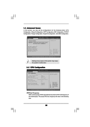
... IDE Configuration PCIPnP Configuration Floppy Configuration SuperIO Configuration USB Configuration Configure CPU Select Screen Select Item Enter Go to malfunction. Setting wrong values in this motherboard. CPU Host Frequency While entering setup, BIOS auto detects the present CPU host frequency of this section may cause the system to set the configurations...
... IDE Configuration PCIPnP Configuration Floppy Configuration SuperIO Configuration USB Configuration Configure CPU Select Screen Select Item Enter Go to malfunction. Setting wrong values in this motherboard. CPU Host Frequency While entering setup, BIOS auto detects the present CPU host frequency of this section may cause the system to set the configurations...
User Manual
Page 32
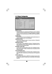
.... DRAM Bank Interleave Use this option to select Active to [20T]. Configuration options: [Auto], [2T], [3T], [4T], and [5T]. The default value is selected, the motherboard will allow better tolerance for memory compatibility when it is [Disabled].
.... DRAM Bank Interleave Use this option to select Active to [20T]. Configuration options: [Auto], [2T], [3T], [4T], and [5T]. The default value is selected, the motherboard will allow better tolerance for memory compatibility when it is [Disabled].

