User Manual
Page 3
Introduction 5 1.1 Package Contents 5 1.2 Specifications 6 1.3 Minimum Hardware Requirement Table for SATA / SATAII HDDs 22 2.10 SATA / SATAII HDD Hot Plug Feature and Operation Guide 23 2.11 Driver Installation Guide 25 2.12 HDMR Card and Driver ...Headers and Connectors 17 2.7 SATAII Hard Disk Setup Guide 21 2.8 Serial ATA (SATA) / Serial ATAII (SATAII) Hard Disks Installation 22 2.9 Hot Plug and Hot Swap Functions for Windows® VistaTM Basic Logo 9 1.4 Motherboard Layout 10 1.5 ASRock 6CH I/O Plus 11 TM 2. BIOS SETUP UTILITY 28 3.1 Introduction 28 3.1.1 BIOS...
Introduction 5 1.1 Package Contents 5 1.2 Specifications 6 1.3 Minimum Hardware Requirement Table for SATA / SATAII HDDs 22 2.10 SATA / SATAII HDD Hot Plug Feature and Operation Guide 23 2.11 Driver Installation Guide 25 2.12 HDMR Card and Driver ...Headers and Connectors 17 2.7 SATAII Hard Disk Setup Guide 21 2.8 Serial ATA (SATA) / Serial ATAII (SATAII) Hard Disks Installation 22 2.9 Hot Plug and Hot Swap Functions for Windows® VistaTM Basic Logo 9 1.4 Motherboard Layout 10 1.5 ASRock 6CH I/O Plus 11 TM 2. BIOS SETUP UTILITY 28 3.1 Introduction 28 3.1.1 BIOS...
User Manual
Page 5
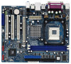
.... Chapter 3 and 4 contain the configuration guide to quality and endurance. www.asrock.com/support/index.asp 1.1 Package Contents ASRock P4VM900-SATA2 Motherboard (Micro ATX Form Factor: 9.6-in x 8.0-in Floppy Drive One Serial ATA (SATA) Cable (Optional) One Serial ATA (SATA) HDD Power Cable (Optional) One ASRock 6CH I/O PlusTM Shield 5 It delivers excellent performance with robust design conforming...
.... Chapter 3 and 4 contain the configuration guide to quality and endurance. www.asrock.com/support/index.asp 1.1 Package Contents ASRock P4VM900-SATA2 Motherboard (Micro ATX Form Factor: 9.6-in x 8.0-in Floppy Drive One Serial ATA (SATA) Cable (Optional) One Serial ATA (SATA) HDD Power Cable (Optional) One ASRock 6CH I/O PlusTM Shield 5 It delivers excellent performance with robust design conforming...
User Manual
Page 8
... 4. Power Management for system usage under Microsoft® Windows® VistaTM / XP SP1 or SP2 / 2000 SP4. 8. You can also connect SATA hard disk to perform over-clocking. About the setting of the system or damage the CPU. 5. Before installing SATAII hard disk to SATAII connector, ...the "SATAII Hard Disk Setup Guide" on updating now. As long as we have the latest driver, we will automatically shutdown. ASRock website http://www.asrock.com 8 Although this motherboard offers stepless control, it is detected, the system will update it back again. While CPU overheat is ...
... 4. Power Management for system usage under Microsoft® Windows® VistaTM / XP SP1 or SP2 / 2000 SP4. 8. You can also connect SATA hard disk to perform over-clocking. About the setting of the system or damage the CPU. 5. Before installing SATAII hard disk to SATAII connector, ...the "SATAII Hard Disk Setup Guide" on updating now. As long as we have the latest driver, we will automatically shutdown. ASRock website http://www.asrock.com 8 Although this motherboard offers stepless control, it is detected, the system will update it back again. While CPU overheat is ...

User Manual
Page 17
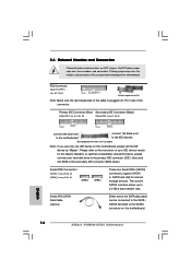
...80-conductor ATA 66/100/133 cable Note: If you use only one IDE device on the motherboard. 17 Serial ATA (SATA) Data Cable (Optional) Either end of the SATA data cable can be connected to Pin1 Note: Make sure the red-striped side of the cable is plugged into Pin1 ... over these headers and connectors. FDD Connector (33-pin FLOPPY1) (see p.10, No. 14) SATAII_2 SATAII_1 These two Serial ATAII (SATAII) connectors support SATAII or SATA hard disk for the details. Serial ATAII Connectors (SATAII_1: see p.10, No. 13) (SATAII_2: see p.10, No. 8) Pin1 FLOPPY1 the red-striped side to ...
...80-conductor ATA 66/100/133 cable Note: If you use only one IDE device on the motherboard. 17 Serial ATA (SATA) Data Cable (Optional) Either end of the SATA data cable can be connected to Pin1 Note: Make sure the red-striped side of the cable is plugged into Pin1 ... over these headers and connectors. FDD Connector (33-pin FLOPPY1) (see p.10, No. 14) SATAII_2 SATAII_1 These two Serial ATAII (SATAII) connectors support SATAII or SATA hard disk for the details. Serial ATAII Connectors (SATAII_1: see p.10, No. 13) (SATAII_2: see p.10, No. 8) Pin1 FLOPPY1 the red-striped side to ...

User Manual
Page 18
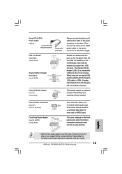
... panel USB ports by attaching the front panel USB cable to USB4_5 header, the USB ports 45 on the drive. Serial ATA (SATA) Power Cable (Optional) connect to the SATA HDD power connector connect to the power supply Please connect the black end of the power supply. Then connect the white end... of SATA power cable to the power connector of SATA power cable to the power connector on the I /O panel, there are two USB 2.0 headers on the chassis must support HDA to...
... panel USB ports by attaching the front panel USB cable to USB4_5 header, the USB ports 45 on the drive. Serial ATA (SATA) Power Cable (Optional) connect to the SATA HDD power connector connect to the power supply Please connect the black end of the power supply. Then connect the white end... of SATA power cable to the power connector of SATA power cable to the power connector on the I /O panel, there are two USB 2.0 headers on the chassis must support HDA to...

User Manual
Page 21
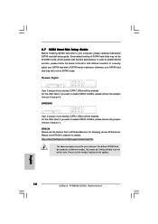
...order to enable SATAII function, please follow the below SATAII hard disk setup guide. Western Digital 7531 8642 If pin 5 and pin 6 are shorted, SATA 1.5Gb/s will be the same. Some default setting of different vendors, the jumper pin setting methods may fail to run at SATAII mode, which .... 21 2.7 SATAII Hard Disk Setup Guide Before installing SATAII hard disk to your reference. SAMSUNG 7531 8642 If pin 3 and pin 4 are shorted, SATA 1.5Gb/s will be at SATAII mode. For different SATAII hard disk products of SATAII hard disks may not be enabled. On the other hand, if...
...order to enable SATAII function, please follow the below SATAII hard disk setup guide. Western Digital 7531 8642 If pin 5 and pin 6 are shorted, SATA 1.5Gb/s will be the same. Some default setting of different vendors, the jumper pin setting methods may fail to run at SATAII mode, which .... 21 2.7 SATAII Hard Disk Setup Guide Before installing SATAII hard disk to your reference. SAMSUNG 7531 8642 If pin 3 and pin 4 are shorted, SATA 1.5Gb/s will be at SATAII mode. For different SATAII hard disk products of SATAII hard disks may not be enabled. On the other hand, if...

User Manual
Page 22
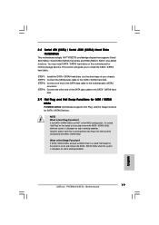
...please note that supports Serial ATA (SATA) / Serial ATAII (SATAII) hard disks and RAID (RAID 0, RAID 1 and JBOD) functions. This section will guide you to the SATA / SATAII hard disk. 2.9 Hot Plug and Hot Swap Functions for SATA / SATAII HDDs P4VM900-SATA2 motherboard supports Hot Plug and Hot ...Swap functions for the action to the SATA / SATAII hard disk. If SATA / SATAII HDDs are NOT set for RAID ...
...please note that supports Serial ATA (SATA) / Serial ATAII (SATAII) hard disks and RAID (RAID 0, RAID 1 and JBOD) functions. This section will guide you to the SATA / SATAII hard disk. 2.9 Hot Plug and Hot Swap Functions for SATA / SATAII HDDs P4VM900-SATA2 motherboard supports Hot Plug and Hot ...Swap functions for the action to the SATA / SATAII hard disk. If SATA / SATAII HDDs are NOT set for RAID ...
User Manual
Page 23
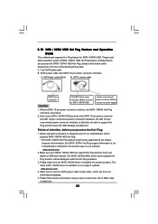
...definitely not able to power supply Caution 1. The latest SATA / SATAII driver is available on our website: www.asrock.com 2. Below operation procedure is designed only for SATA / SATAII HDD. Without SATA 15-pin power connector interface, the SATA / SATAII Hot Plug cannot be damaged under the Hot...below instructions step by the chipset because of its limitation, the SATA / SATAII Hot Plug support information of our motherboard is indicated in the product spec on our support website: www.asrock.com 4. 2.10 SATA / SATAII HDD Hot Plug Feature and Operation Guide This motherboard ...
...definitely not able to power supply Caution 1. The latest SATA / SATAII driver is available on our website: www.asrock.com 2. Below operation procedure is designed only for SATA / SATAII HDD. Without SATA 15-pin power connector interface, the SATA / SATAII Hot Plug cannot be damaged under the Hot...below instructions step by the chipset because of its limitation, the SATA / SATAII Hot Plug support information of our motherboard is indicated in the product spec on our support website: www.asrock.com 4. 2.10 SATA / SATAII HDD Hot Plug Feature and Operation Guide This motherboard ...

User Manual
Page 24
... process the Hot Plug, improper procedure will cause the SATA / SATAII HDD damage and data loss. Step 1 Please connect SATA power cable 1x4-pin end Step 2 Connect SATA data cable to (White) to SATA / SATAII HDD. How to Hot Unplug a SATA / SATAII HDD: Points of attention, before you process... 1x4-pin cable. Step 1 Unplug SATA data cable from SATA / SATAII HDD side. 24 Step 2 Unplug SATA 15-pin power cable connector (Black) from SATA / SATAII HDD side. Step 4 Connect SATA data cable to process the Hot Unplug, improper procedure will cause the SATA / SATAII HDD damage and data loss...
... process the Hot Plug, improper procedure will cause the SATA / SATAII HDD damage and data loss. Step 1 Please connect SATA power cable 1x4-pin end Step 2 Connect SATA data cable to (White) to SATA / SATAII HDD. How to Hot Unplug a SATA / SATAII HDD: Points of attention, before you process... 1x4-pin cable. Step 1 Unplug SATA data cable from SATA / SATAII HDD side. 24 Step 2 Unplug SATA 15-pin power cable connector (Black) from SATA / SATAII HDD side. Step 4 Connect SATA data cable to process the Hot Unplug, improper procedure will cause the SATA / SATAII HDD damage and data loss...
User Manual
Page 25
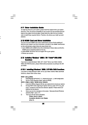
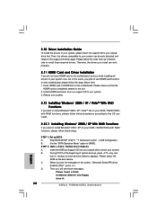
...2.13 Installing Windows® 2000 / XP / VistaTM With RAID Functions If you install can be auto-detected and listed on this motherboard. Insert the ASRock Support CD into floppy drive A: 25 B. Therefore, the drivers you want to [RAID]. A 2. ROM as the boot device. Please select CD- ...During POST at the beginning of system boot-up BIOS. Set the "SATA Operation Mode" option to install Windows® 2000 / XP / VistaTM OS on your SATA / SATAII HDDs with RAID functions, please follow the steps below procedures according to the OS you ...
...2.13 Installing Windows® 2000 / XP / VistaTM With RAID Functions If you install can be auto-detected and listed on this motherboard. Insert the ASRock Support CD into floppy drive A: 25 B. Therefore, the drivers you want to [RAID]. A 2. ROM as the boot device. Please select CD- ...During POST at the beginning of system boot-up BIOS. Set the "SATA Operation Mode" option to install Windows® 2000 / XP / VistaTM OS on your SATA / SATAII HDDs with RAID functions, please follow the steps below procedures according to the OS you ...

User Manual
Page 26
...install a third-party RAID driver. Enter BIOS SETUP UTILITY Advanced screen IDE Configuration. If you want to install Windows® VistaTM on your SATA / SATAII HDDs with RAID functions, please follow the instruction to check the RAID installation guide in the Support CD: .. \ RAID Installation ...to check the RAID installation guide in Windows® environment, please install SATA / SATAII drivers from the Support CD again so that "VIA RAID Tool" will be presented. page, please insert the ASRock Support CD into the floppy drive, and press any key to start to...
...install a third-party RAID driver. Enter BIOS SETUP UTILITY Advanced screen IDE Configuration. If you want to install Windows® VistaTM on your SATA / SATAII HDDs with RAID functions, please follow the instruction to check the RAID installation guide in the Support CD: .. \ RAID Installation ...to check the RAID installation guide in Windows® environment, please install SATA / SATAII drivers from the Support CD again so that "VIA RAID Tool" will be presented. page, please insert the ASRock Support CD into the floppy drive, and press any key to start to...
User Manual
Page 27
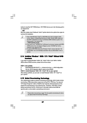
... operate under Windows® VistaTM, please right-click "VIA V-Raid Utility" icon on the desktop and select "Run as well. 3. Set the "SATA Operation Mode" option to load the VIA® RAID drivers. After setting up BIOS. You may set the RAID configuration by using the Windows RAID...during overclocking, FSB enjoys better margin due to continue the installation. 1. Please refer to install Windows® 2000 / XP / VistaTM OS on SATA / SATAII HDDs, please set "CPU Host Frequency" option of BIOS setup to manage (create, convert, delete or rebuild) RAID functions on your system.
... operate under Windows® VistaTM, please right-click "VIA V-Raid Utility" icon on the desktop and select "Run as well. 3. Set the "SATA Operation Mode" option to load the VIA® RAID drivers. After setting up BIOS. You may set the RAID configuration by using the Windows RAID...during overclocking, FSB enjoys better margin due to continue the installation. 1. Please refer to install Windows® 2000 / XP / VistaTM OS on SATA / SATAII HDDs, please set "CPU Host Frequency" option of BIOS setup to manage (create, convert, delete or rebuild) RAID functions on your system.
User Manual
Page 36
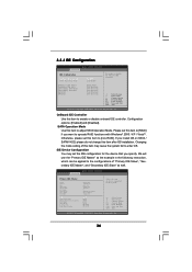
... setting of device connected to operate RAID functions with Windows® 2000 / XP / VistaTM. Configuration options: [Enabled] and [Disabled]. SATA Operation Mode Use this item after OS installation. IDE Device Configuration You may cause the system fail to enable or disable onboard IDE controller.... [Enabled] [non-RAID] To enable or disable the onboard IDE controller. Primary IDE Master Primary IDE Slave Secondary IDE Master Secondary IDE Slave SATA 1 SATA 2 [Hard Disk] [Not Detected] [Not Detected] [Not Detected] [Not Detected] [Not Detected] +F1 F9 F10 ESC Select Screen ...
... setting of device connected to operate RAID functions with Windows® 2000 / XP / VistaTM. Configuration options: [Enabled] and [Disabled]. SATA Operation Mode Use this item after OS installation. IDE Device Configuration You may cause the system fail to enable or disable onboard IDE controller.... [Enabled] [non-RAID] To enable or disable the onboard IDE controller. Primary IDE Master Primary IDE Slave Secondary IDE Master Secondary IDE Slave SATA 1 SATA 2 [Hard Disk] [Not Detected] [Not Detected] [Not Detected] [Not Detected] [Not Detected] +F1 F9 F10 ESC Select Screen ...

Quick Installation Guide
Page 4
... be found in the user manual presented in Floppy Drive One Serial ATA (SATA) Cable (Optional) One Serial ATA (SATA) HDD Power Cable (Optional) One ASRock 6CH I/O PlusTM Shield 4 ASRock P4VM900-SATA2 Motherboard English It delivers excellent performance with robust design conforming to ASRock's commitment to change without further notice. In case any modifications of the motherboard...
... be found in the user manual presented in Floppy Drive One Serial ATA (SATA) Cable (Optional) One Serial ATA (SATA) HDD Power Cable (Optional) One ASRock 6CH I/O PlusTM Shield 4 ASRock P4VM900-SATA2 Motherboard English It delivers excellent performance with robust design conforming to ASRock's commitment to change without further notice. In case any modifications of the motherboard...
Quick Installation Guide
Page 7
... recommended CPU bus frequencies may cause the instability of "User Manual" in the future. This motherboard supports Untied Overclocking Technology. ASRock website http://www.asrock.com 7 ASRock P4VM900-SATA2 Motherboard English Frequencies other than 4GB for the reservation for USB 2.0 works fine under Windows® XP and Windows® ... of "Hyper Threading Technology", please check page 31 of the system or damage the CPU. 5. You can also connect SATA hard disk to our website in the support CD. 2. As long as we have the latest driver, we will automatically shutdown.
... recommended CPU bus frequencies may cause the instability of "User Manual" in the future. This motherboard supports Untied Overclocking Technology. ASRock website http://www.asrock.com 7 ASRock P4VM900-SATA2 Motherboard English Frequencies other than 4GB for the reservation for USB 2.0 works fine under Windows® XP and Windows® ... of "Hyper Threading Technology", please check page 31 of the system or damage the CPU. 5. You can also connect SATA hard disk to our website in the support CD. 2. As long as we have the latest driver, we will automatically shutdown.
Quick Installation Guide
Page 14
..., see p.2, No. 10) (39-pin IDE2, see p.2, No. 14) SATAII_2 SATAII_1 These two Serial ATAII (SATAII) connectors support SATAII or SATA hard disk for the details. Do NOT place jumper caps over the headers and connectors will cause permanent damage of the connector. Placing jumper caps...allows up to the IDE devices 80-conductor ATA 66/100/133 cable Note: If you use only one IDE device on the motherboard. 14 ASRock P4VM900-SATA2 Motherboard English Serial ATAII Connectors (SATAII_1: see p.2, No. 13) (SATAII_2: see p.2, No. 9) connect the blue end connect the black end...
..., see p.2, No. 10) (39-pin IDE2, see p.2, No. 14) SATAII_2 SATAII_1 These two Serial ATAII (SATAII) connectors support SATAII or SATA hard disk for the details. Do NOT place jumper caps over the headers and connectors will cause permanent damage of the connector. Placing jumper caps...allows up to the IDE devices 80-conductor ATA 66/100/133 cable Note: If you use only one IDE device on the motherboard. 14 ASRock P4VM900-SATA2 Motherboard English Serial ATAII Connectors (SATAII_1: see p.2, No. 13) (SATAII_2: see p.2, No. 9) connect the blue end connect the black end...
Quick Installation Guide
Page 15
... and chassis manual to function correctly. Besides six default USB 2.0 ports on the chassis must support HDA to install your system. 15 ASRock P4VM900-SATA2 Motherboard When using the front panel USB ports by attaching the front panel USB cable to USB4_5 header, the USB ports 45 on the... I /O panel, there are two USB 2.0 headers on the drive. Serial ATA (SATA) Power Cable (Optional) connect to the SATA HDD power connector connect to the power supply USB 2.0 Header (9-pin USB67) (see p.2, No. 16) Shared USB 2.0 Header (9-pin ...
... and chassis manual to function correctly. Besides six default USB 2.0 ports on the chassis must support HDA to install your system. 15 ASRock P4VM900-SATA2 Motherboard When using the front panel USB ports by attaching the front panel USB cable to USB4_5 header, the USB ports 45 on the... I /O panel, there are two USB 2.0 headers on the drive. Serial ATA (SATA) Power Cable (Optional) connect to the SATA HDD power connector connect to the power supply USB 2.0 Header (9-pin USB67) (see p.2, No. 16) Shared USB 2.0 Header (9-pin ...
Quick Installation Guide
Page 18
...follow the below SATAII hard disk setup guide. HITACHI Please use the Feature Tool, a DOS-bootable tool, for the updates. 18 ASRock P4VM900-SATA2 Motherboard English Please visit HITACHI's website for your computer, please carefully read below instruction with different vendors to correctly adjust your SATAII hard ... disk to enable SATAII 3.0Gb/s, please remove the jumpers from pin 5 and pin 6. SAMSUNG If pin 3 and pin 4 are shorted, SATA 1.5Gb/s will be at SATAII mode. On the other hand, if you want to your reference. Please visit the vendors' website for changing...
...follow the below SATAII hard disk setup guide. HITACHI Please use the Feature Tool, a DOS-bootable tool, for the updates. 18 ASRock P4VM900-SATA2 Motherboard English Please visit HITACHI's website for your computer, please carefully read below instruction with different vendors to correctly adjust your SATAII hard ... disk to enable SATAII 3.0Gb/s, please remove the jumpers from pin 5 and pin 6. SAMSUNG If pin 3 and pin 4 are shorted, SATA 1.5Gb/s will be at SATAII mode. On the other hand, if you want to your reference. Please visit the vendors' website for changing...
Quick Installation Guide
Page 19
... guide you to insert and remove the SATA / SATAII HDDs while the system is still power-on and in working condition. 19 ASRock P4VM900-SATA2 Motherboard English STEP 4: Connect the other end of the SATA data cable to insert and remove the SATA / SATAII HDDs while the system is still... power-on and in working condition. NOTE What is Hot Swap Function? If SATA / SATAII HDDs are NOT...
... guide you to insert and remove the SATA / SATAII HDDs while the system is still power-on and in working condition. 19 ASRock P4VM900-SATA2 Motherboard English STEP 4: Connect the other end of the SATA data cable to insert and remove the SATA / SATAII HDDs while the system is still... power-on and in working condition. NOTE What is Hot Swap Function? If SATA / SATAII HDDs are NOT...
Quick Installation Guide
Page 20
...drive to boot your system. B. ROM as the boot device. D. A. When you want to install those required drivers. Set the "SATA Operation Mode" option to your optical drive first. 2.10 Driver Installation Guide To install the drivers to your system, please insert the ...to install Windows® 2000 / XP on the support CD driver page. STEP 2: Make a SATA / SATAII driver diskette. Insert the ASRock Support CD into floppy drive A: 20 ASRock P4VM900-SATA2 Motherboard English During POST at the beginning of system boot-up BIOS. Then you install can be auto...
...drive to boot your system. B. ROM as the boot device. D. A. When you want to install those required drivers. Set the "SATA Operation Mode" option to your optical drive first. 2.10 Driver Installation Guide To install the drivers to your system, please insert the ...to install Windows® 2000 / XP on the support CD driver page. STEP 2: Make a SATA / SATAII driver diskette. Insert the ASRock Support CD into floppy drive A: 20 ASRock P4VM900-SATA2 Motherboard English During POST at the beginning of system boot-up BIOS. Then you install can be auto...
