
User Manual
Page 3
... 36 3.5.1 Boot Settings Configuration 37 3.6 Security Screen 37 3 Introduction 5 1.1 Package Contents 5 1.2 Specifications 6 1.3 Motherboard Layout 9 1.4 ASRock I/O Plus 10 TM 2. Installation 11 Pre-installation Precautions 11 2.1 CPU Installation 12 2.2 Installation of CPU Fan and Heatsink 12 2.3 Installation of Memory Modules (DIMM 13 2.4 Expansion Slots (PCI, AMR, and PCI Express Slots) .... 14 2.5 Jumpers Setup 15...
... 36 3.5.1 Boot Settings Configuration 37 3.6 Security Screen 37 3 Introduction 5 1.1 Package Contents 5 1.2 Specifications 6 1.3 Motherboard Layout 9 1.4 ASRock I/O Plus 10 TM 2. Installation 11 Pre-installation Precautions 11 2.1 CPU Installation 12 2.2 Installation of CPU Fan and Heatsink 12 2.3 Installation of Memory Modules (DIMM 13 2.4 Expansion Slots (PCI, AMR, and PCI Express Slots) .... 14 2.5 Jumpers Setup 15...
User Manual
Page 6
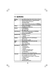
... Plus - 2 x DDR DIMM slots - capacity: 2GB - Integrated VIA® UniChrome Pro 3D/2D Graphics - shared memory 64MB - Speed: 10/100 Ethernet - Northbridge: VIA® P4M890 - ASRock U-COP (see CAUTION 1) - Boot Failure Guard (B.F.G.) - 3 x PCI slots - 1 x PCI Express x16 slot... - 1 x AMR slot - CPU/Chassis FAN connector 6 Supports Hyper-Threading Technology (see CAUTION 4) - DirectX 7.0 VGA - Supports Wake-On-LAN ASRock I /O Connector - Audio Jack: Line in , 24.4 cm x 20.3 cm - Supports Untied Overclocking Technology (see CAUTION 3) - Support DDR400/333 - CPU...
... Plus - 2 x DDR DIMM slots - capacity: 2GB - Integrated VIA® UniChrome Pro 3D/2D Graphics - shared memory 64MB - Speed: 10/100 Ethernet - Northbridge: VIA® P4M890 - ASRock U-COP (see CAUTION 1) - Boot Failure Guard (B.F.G.) - 3 x PCI slots - 1 x PCI Express x16 slot... - 1 x AMR slot - CPU/Chassis FAN connector 6 Supports Hyper-Threading Technology (see CAUTION 4) - DirectX 7.0 VGA - Supports Wake-On-LAN ASRock I /O Connector - Audio Jack: Line in , 24.4 cm x 20.3 cm - Supports Untied Overclocking Technology (see CAUTION 3) - Support DDR400/333 - CPU...
User Manual
Page 9
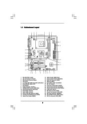
Blue) 20 Clear CMOS Jumper (CLRCMOS1) 6 Infrared Module Header (IR1) 21 JR1 / JL1 Jumpers 7 Flash Memory 22 Front Panel Audio Header (AUDIO1) 8 Floppy Connector (FLOPPY1) 23 Internal Audio Connector: CD1 (Black) 9 Secondary IDE Connector (IDE2, Black) 24 Internal Audio ... VIA P4M890 Chipset USB4_5 CHA_FAN1 5.1CH LAN PHY CMOS Battery CD1 AUX1 Audio AUDIO1 CODEC 1 JR1 JL1 CLRCMOS1 RoHS PCIE1 PCI EXPRESS IDE1 IDE2 PCI 1 ` P4VM890 PCI 2 PCI 3 ATA133 AMR1 1 COM1 1 USB67 1 SPEAKER1 PANEL 1 PLED PWRBTN 1 HDLED RESET VIA VT8237R Plus SATA2 SATA1 SATA 9 10 11 12 21 ...
Blue) 20 Clear CMOS Jumper (CLRCMOS1) 6 Infrared Module Header (IR1) 21 JR1 / JL1 Jumpers 7 Flash Memory 22 Front Panel Audio Header (AUDIO1) 8 Floppy Connector (FLOPPY1) 23 Internal Audio Connector: CD1 (Black) 9 Secondary IDE Connector (IDE2, Black) 24 Internal Audio ... VIA P4M890 Chipset USB4_5 CHA_FAN1 5.1CH LAN PHY CMOS Battery CD1 AUX1 Audio AUDIO1 CODEC 1 JR1 JL1 CLRCMOS1 RoHS PCIE1 PCI EXPRESS IDE1 IDE2 PCI 1 ` P4VM890 PCI 2 PCI 3 ATA133 AMR1 1 COM1 1 USB67 1 SPEAKER1 PANEL 1 PLED PWRBTN 1 HDLED RESET VIA VT8237R Plus SATA2 SATA1 SATA 9 10 11 12 21 ...
User Manual
Page 13
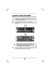
... in one correct orientation. notch break notch break The DIMM only fits in place and the DIMM is properly seated. 13 Step 3. 2.3 Installation of Memory Modules (DIMM) P4VM890 motherboard provides two 184-pin DDR (Double Data Rate) DIMM slots. Please make sure to the motherboard and the DIMM if you force the...
... in one correct orientation. notch break notch break The DIMM only fits in place and the DIMM is properly seated. 13 Step 3. 2.3 Installation of Memory Modules (DIMM) P4VM890 motherboard provides two 184-pin DDR (Double Data Rate) DIMM slots. Please make sure to the motherboard and the DIMM if you force the...

User Manual
Page 23
The Flash Memory on . You may also restart by pressing the reset button on the menu bar, and then press to choose among the selections on the system ...
The Flash Memory on . You may also restart by pressing the reset button on the menu bar, and then press to choose among the selections on the system ...

User Manual
Page 24
... System Time System Date [16:15:31] [Mon 12/25/2006] BIOS Version : P4VM890 BIOS P1.00 Processor Type : Intel (R) Pentium (R) 4 CPU 2.40GHz Processor Speed : 2400MHz Microcode Update : F33/C Cache Size : 1024KB Total Memory DDR1 DDR2 : 256MB with 64MB shared memory : 256MB/166MHz (DDR333) : None Use [Enter], [TAB] or [SHIFT-TAB] to configure...
... System Time System Date [16:15:31] [Mon 12/25/2006] BIOS Version : P4VM890 BIOS P1.00 Processor Type : Intel (R) Pentium (R) 4 CPU 2.40GHz Processor Speed : 2400MHz Microcode Update : F33/C Cache Size : 1024KB Total Memory DDR1 DDR2 : 256MB with 64MB shared memory : 256MB/166MHz (DDR333) : None Use [Enter], [TAB] or [SHIFT-TAB] to configure...

User Manual
Page 27
...333)] and [200MHz (DDR 400)]. Flexibility Option The default value of this option to select Precharge to [20]. It will detect the memory module(s) inserted and assigns appropriate frequency automatically. Configuration options: [Auto], [2], [2.5], and [3]. The default value is selected, the motherboard will allow better ...Recovery Time (Twr) DRAM Command Rate [Auto] [Disabled] [Auto] [Auto] [Auto] [Auto] [Auto] [Auto] [Auto] [Auto] [Auto] [Auto] [2T Command] Memory Clock can be set by the code using AUTO, or you can set the timing by dram SPD. DRAM CAS# Latency Use this option to...
...333)] and [200MHz (DDR 400)]. Flexibility Option The default value of this option to select Precharge to [20]. It will detect the memory module(s) inserted and assigns appropriate frequency automatically. Configuration options: [Auto], [2], [2.5], and [3]. The default value is selected, the motherboard will allow better ...Recovery Time (Twr) DRAM Command Rate [Auto] [Disabled] [Auto] [Auto] [Auto] [Auto] [Auto] [Auto] [Auto] [Auto] [Auto] [Auto] [2T Command] Memory Clock can be set by the code using AUTO, or you can set the timing by dram SPD. DRAM CAS# Latency Use this option to...

User Manual
Page 28
...: [Auto], [2T], [3T], [4T], and [5T]. DRAM Command Rate Use this option to select Write to Read CMD (Twtr). It allows you to set share memory feature. REF to ACT / REF to REF (Trfc) Use this to select VDDQ voltage. Configuration options: [Auto], [Normal] and [High]. Share... Memory This allows you to set the North Bridge and South Bridge V-Link Speed of VIA chipset. Configuration options: [Auto], [2T], [3T]. VDDQ Voltage Use this ...
...: [Auto], [2T], [3T], [4T], and [5T]. DRAM Command Rate Use this option to select Write to Read CMD (Twtr). It allows you to set share memory feature. REF to ACT / REF to REF (Trfc) Use this to select VDDQ voltage. Configuration options: [Auto], [Normal] and [High]. Share... Memory This allows you to set the North Bridge and South Bridge V-Link Speed of VIA chipset. Configuration options: [Auto], [2T], [3T]. VDDQ Voltage Use this ...

Quick Installation Guide
Page 2
... 1 PS2_USB_PWR1 Jumper 2 ATX 12V Connector (ATX12V1) 3 CPU Heatsink Retention Module 4 CPU Socket 5 2 x 184-pin DDR DIMM Slots (DDR1, DDR2; Blue) 6 Infrared Module Header (IR1) 7 Flash Memory 8 Floppy Connector (FLOPPY1) 9 Secondary IDE Connector (IDE2, Black) 10 Primary IDE Connector (IDE1, Blue) 11 North Bridge Controller 12 South Bridge Controller 13 Primary Serial... Express x16 Slot (PCIE1) 27 Chassis Fan Connector (CHA_FAN1) 28 ATX Power Connector (ATXPWR1) 29 Shared USB 2.0 Header (USB4_5, Blue) 30 CPU Fan Connector (CPU_FAN1) 2 ASRock P4VM890 Motherboard
... 1 PS2_USB_PWR1 Jumper 2 ATX 12V Connector (ATX12V1) 3 CPU Heatsink Retention Module 4 CPU Socket 5 2 x 184-pin DDR DIMM Slots (DDR1, DDR2; Blue) 6 Infrared Module Header (IR1) 7 Flash Memory 8 Floppy Connector (FLOPPY1) 9 Secondary IDE Connector (IDE2, Black) 10 Primary IDE Connector (IDE1, Blue) 11 North Bridge Controller 12 South Bridge Controller 13 Primary Serial... Express x16 Slot (PCIE1) 27 Chassis Fan Connector (CHA_FAN1) 28 ATX Power Connector (ATXPWR1) 29 Shared USB 2.0 Header (USB4_5, Blue) 30 CPU Fan Connector (CPU_FAN1) 2 ASRock P4VM890 Motherboard

Quick Installation Guide
Page 5
FSB 800/533/400 MHz - Supports Hyper-Threading Technology (see CAUTION 3) - capacity: 2GB - Supports Wake-On-LAN ASRock I /O Connector - 1.2 Specifications Platform CPU Chipset Memory Hybrid Booster Expansion Slot Graphics Audio LAN Rear Panel I /O PlusTM - 1 x PS/2 Mouse Port - 1 x PS/2 ... CAUTION 1) - Speed: 10/100 Ethernet - CPU/Chassis FAN connector 5 ASRock P4VM890 Motherboard English Northbridge: VIA® P4M890 - shared memory 64MB - Realtek ALC653 5.1channel AC'97 audio codec - ASRock U-COP (see CAUTION 2) - Integrated VIA® UniChrome Pro 3D/2D Graphics...
FSB 800/533/400 MHz - Supports Hyper-Threading Technology (see CAUTION 3) - capacity: 2GB - Supports Wake-On-LAN ASRock I /O Connector - 1.2 Specifications Platform CPU Chipset Memory Hybrid Booster Expansion Slot Graphics Audio LAN Rear Panel I /O PlusTM - 1 x PS/2 Mouse Port - 1 x PS/2 ... CAUTION 1) - Speed: 10/100 Ethernet - CPU/Chassis FAN connector 5 ASRock P4VM890 Motherboard English Northbridge: VIA® P4M890 - shared memory 64MB - Realtek ALC653 5.1channel AC'97 audio codec - ASRock U-COP (see CAUTION 2) - Integrated VIA® UniChrome Pro 3D/2D Graphics...

Quick Installation Guide
Page 10
... the DIMM matches the break on the slot. Step 1. 2.3 Installation of Memory Modules (DIMM) P4VM890 motherboard provides two 184-pin DDR (Double Data Rate) DIMM slots. Step 2. The DIMM only fits in place and the DIMM is properly seated. 10 ASRock P4VM890 Motherboard English Firmly insert the DIMM into the slot at both ends...
... the DIMM matches the break on the slot. Step 1. 2.3 Installation of Memory Modules (DIMM) P4VM890 motherboard provides two 184-pin DDR (Double Data Rate) DIMM slots. Step 2. The DIMM only fits in place and the DIMM is properly seated. 10 ASRock P4VM890 Motherboard English Firmly insert the DIMM into the slot at both ends...

Quick Installation Guide
Page 19
...Test (POST) to enter BIOS Setup utility; You may set "CPU Host Frequency" option of BIOS setup to display the menus. 19 ASRock P4VM890 Motherboard English Please refer to the warning on the file "ASSETUP.EXE" from the BIN folder in the following item. Software Support CD ...appear automatically, locate and double-click on page 6 for the possible overclocking risk before you wish to be user-friendly. BIOS Information The Flash Memory on the system chassis. If you apply Untied Overclocking Technology. 3. Therefore, CPU FSB is untied during overclocking, but PCI / PCIE bus ...
...Test (POST) to enter BIOS Setup utility; You may set "CPU Host Frequency" option of BIOS setup to display the menus. 19 ASRock P4VM890 Motherboard English Please refer to the warning on the file "ASSETUP.EXE" from the BIN folder in the following item. Software Support CD ...appear automatically, locate and double-click on page 6 for the possible overclocking risk before you wish to be user-friendly. BIOS Information The Flash Memory on the system chassis. If you apply Untied Overclocking Technology. 3. Therefore, CPU FSB is untied during overclocking, but PCI / PCIE bus ...

