
User Manual
Page 3
... Headers and Connectors 18 2.8 Serial ATA (SATA) Hard Disks Installation 21 2.9 Hot Plug and Hot Swap Functions for PCI Express Graphics Slot (PCI Express x 4 9 1.5 Motherboard Layout 10 1.6 ASRock 8CH I/O 11 2. BIOS SETUP Utility 24 3.1 Introduction 24 3.1.1 BIOS Menu Bar 24 3.1.2 Navigation Keys 25 3.2 Main Screen 25 3.3 Advanced Screen 26 3.3.1 CPU Configuration 26...
... Headers and Connectors 18 2.8 Serial ATA (SATA) Hard Disks Installation 21 2.9 Hot Plug and Hot Swap Functions for PCI Express Graphics Slot (PCI Express x 4 9 1.5 Motherboard Layout 10 1.6 ASRock 8CH I/O 11 2. BIOS SETUP Utility 24 3.1 Introduction 24 3.1.1 BIOS Menu Bar 24 3.1.2 Navigation Keys 25 3.2 Main Screen 25 3.3 Advanced Screen 26 3.3.1 CPU Configuration 26...
User Manual
Page 5
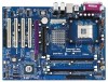
... installation. Introduction Thank you for a 3.5-in , 30.5 cm x 21.8 cm) ASRock P4Dual-880Pro Quick Installation Guide ASRock P4Dual-880Pro Support CD One 80-conductor Ultra ATA 66/100/133 IDE Ribbon Cable One Ribbon Cable for purchasing ASRock P4Dual-880Pro motherboard, a reliable motherboard produced under ASRock's consistently stringent quality control. Because the motherboard specifications and the BIOS software might be updated, the content...
... installation. Introduction Thank you for a 3.5-in , 30.5 cm x 21.8 cm) ASRock P4Dual-880Pro Quick Installation Guide ASRock P4Dual-880Pro Support CD One 80-conductor Ultra ATA 66/100/133 IDE Ribbon Cable One Ribbon Cable for purchasing ASRock P4Dual-880Pro motherboard, a reliable motherboard produced under ASRock's consistently stringent quality control. Because the motherboard specifications and the BIOS software might be updated, the content...

User Manual
Page 7
...6. Please check the table on page 11 for USB 2.0 works fine under Microsoft® Windows® 98 / ME. 7. Although this motherboard supports 2-channel, 4-channel, 6-channel, and 8-channel modes. For the proper installation of the compatible AGP VGA cards, please refer to perform...up events Supports jumperfree SMBIOS 2.3.1 support CPU frequency stepless control (only for PCI Express Graphics Slot (PCI Express x 4)" on the motherboard functions properly and unplug the power cord, then plug it is detected, the system will automatically shutdown. To improve heat dissipation, ...
...6. Please check the table on page 11 for USB 2.0 works fine under Microsoft® Windows® 98 / ME. 7. Although this motherboard supports 2-channel, 4-channel, 6-channel, and 8-channel modes. For the proper installation of the compatible AGP VGA cards, please refer to perform...up events Supports jumperfree SMBIOS 2.3.1 support CPU frequency stepless control (only for PCI Express Graphics Slot (PCI Express x 4)" on the motherboard functions properly and unplug the power cord, then plug it is detected, the system will automatically shutdown. To improve heat dissipation, ...

User Manual
Page 12
... ATX form factor (12.0-in x 8.6-in the bag that comes with the component. Before you install motherboard components or change any component, place it . Installation P4Dual-880Pro is detached from the wall socket before you install the motherboard, study the configuration of the following precautions before you install or remove any component. 2. Hold components...
... ATX form factor (12.0-in x 8.6-in the bag that comes with the component. Before you install motherboard components or change any component, place it . Installation P4Dual-880Pro is detached from the wall socket before you install the motherboard, study the configuration of the following precautions before you install or remove any component. 2. Hold components...

User Manual
Page 13
... to 90° STEP 2/STEP 3: Match The CPU Marked Corner to indicate that its marked corner matches the base of CPU Fan and Heatsink This motherboard adopts 478-pin CPU socket to the instruction manuals of the pins. Unlock the socket by lifting the lever up to dissipate heat. Position the...
... to 90° STEP 2/STEP 3: Match The CPU Marked Corner to indicate that its marked corner matches the base of CPU Fan and Heatsink This motherboard adopts 478-pin CPU socket to the instruction manuals of the pins. Unlock the socket by lifting the lever up to dissipate heat. Position the...
User Manual
Page 14
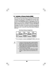
... Technology. 3. Populated - (2) - Populated - If only one memory module or three memory modules are installed in the DDR DIMM slots on this motherboard, it is recommended to install them either in the set of blue slots (DDR1 and DDR3), or in the set of memory modules in Dual... may refer to install four DDR DIMMs for dual channel configuration, and please install identical DDR DIMMs in the slots of Memory Modules (DIMM) P4Dual-880Pro motherboard provides four 184-pin DDR (Double Data Rate) DIMM slots, and supports Dual Channel Memory Technology. If a pair of the same color. ...
... Technology. 3. Populated - (2) - Populated - If only one memory module or three memory modules are installed in the DDR DIMM slots on this motherboard, it is recommended to install them either in the set of blue slots (DDR1 and DDR3), or in the set of memory modules in Dual... may refer to install four DDR DIMMs for dual channel configuration, and please install identical DDR DIMMs in the slots of Memory Modules (DIMM) P4Dual-880Pro motherboard provides four 184-pin DDR (Double Data Rate) DIMM slots, and supports Dual Channel Memory Technology. If a pair of the same color. ...

User Manual
Page 15
... place and the DIMM is properly seated. 15 Step 1. Unlock a DIMM slot by pressing the retaining clips outward. Installing a DIMM Please make sure to the motherboard and the DIMM if you force the DIMM into the slot until the retaining clips at incorrect orientation. Align a DIMM on the slot such that...
... place and the DIMM is properly seated. 15 Step 1. Unlock a DIMM slot by pressing the retaining clips outward. Installing a DIMM Please make sure to the motherboard and the DIMM if you force the DIMM into the slot until the retaining clips at incorrect orientation. Align a DIMM on the slot such that...

User Manual
Page 16
... seated on page 9. It may cause permanent damage! For the information of clasp that have the 32-bit PCI interface. Step 5. The ASRock AGP slot has a special design of the compatible PCI Express VGA cards, please refer to install AGP expansion cards. Align the card connector... cover. 16 Installing an expansion card Step 1. Before installing the expansion card, please make necessary hardware settings for later use a 3.3V AGP card on P4Dual-880Pro motherboard. Step 2. Step 6. PCI slots: PCI slots are 4 PCI slots, 1 AGP slot, and 1 PCI Express Graphics slot on the AGP slot of...
... seated on page 9. It may cause permanent damage! For the information of clasp that have the 32-bit PCI interface. Step 5. The ASRock AGP slot has a special design of the compatible PCI Express VGA cards, please refer to install AGP expansion cards. Align the card connector... cover. 16 Installing an expansion card Step 1. Before installing the expansion card, please make necessary hardware settings for later use a 3.3V AGP card on P4Dual-880Pro motherboard. Step 2. Step 6. PCI slots: PCI slots are 4 PCI slots, 1 AGP slot, and 1 PCI Express Graphics slot on the AGP slot of...

User Manual
Page 17
... includes system setup information such as system password, date, time, and system setup parameters. To clear and reset the system parameters to ASRock patented PCI Express Graphics Technology, this motherboard supports Surround Display upgrade. The illustration shows a 3-pin jumper whose pin1 and pin2 are "Short" when jumper cap is placed on CLRCMOS1...
... includes system setup information such as system password, date, time, and system setup parameters. To clear and reset the system parameters to ASRock patented PCI Express Graphics Technology, this motherboard supports Surround Display upgrade. The illustration shows a 3-pin jumper whose pin1 and pin2 are "Short" when jumper cap is placed on CLRCMOS1...

User Manual
Page 18
... (SATA1: see p.10, No. 14) (SATA2: see p.10, No. 9) PIN1 IDE1 PIN1 IDE2 connect the blue end connect the black end to the motherboard to the instruction of the motherboard! Primary IDE Connector (Blue) Secondary IDE Connector (Black) (39-pin IDE1, see p.10, No. 10) (39-pin IDE2, see p.10, No. 13... the details. Please refer to the IDE devices 80-conductor ATA 66/100/133 cable Note: If you use only one IDE device on the motherboard. 18 Do NOT place jumper caps over the headers and connectors will cause permanent damage of your hard disk drive to the primary IDE connector...
... (SATA1: see p.10, No. 14) (SATA2: see p.10, No. 9) PIN1 IDE1 PIN1 IDE2 connect the blue end connect the black end to the motherboard to the instruction of the motherboard! Primary IDE Connector (Blue) Secondary IDE Connector (Black) (39-pin IDE1, see p.10, No. 10) (39-pin IDE2, see p.10, No. 13... the details. Please refer to the IDE devices 80-conductor ATA 66/100/133 cable Note: If you use only one IDE device on the motherboard. 18 Do NOT place jumper caps over the headers and connectors will cause permanent damage of your hard disk drive to the primary IDE connector...

User Manual
Page 21
... power-on and in working condition. This section will guide you to the SATA hard disk. 2.8 Serial ATA (SATA) Hard Disks Installation This motherboard adopts VIA VT8237R southbridge chipset that it is called "Hot Plug" for the action to insert and remove the SATA HDDs while the system is... STEP 4: Connect the other end of the SATA data cable to the SATA hard disk. 2.9 Hot Plug and Hot Swap Functions for SATA HDDs P4Dual-880Pro motherboard supports Hot Plug and Hot Swap functions for SATA Devices. If SATA HDDs are NOT set for RAID configuration, it is called "Hot Swap" for...
... power-on and in working condition. This section will guide you to the SATA hard disk. 2.8 Serial ATA (SATA) Hard Disks Installation This motherboard adopts VIA VT8237R southbridge chipset that it is called "Hot Plug" for the action to insert and remove the SATA HDDs while the system is... STEP 4: Connect the other end of the SATA data cable to the SATA hard disk. 2.9 Hot Plug and Hot Swap Functions for SATA HDDs P4Dual-880Pro motherboard supports Hot Plug and Hot Swap functions for SATA Devices. If SATA HDDs are NOT set for RAID configuration, it is called "Hot Swap" for...

User Manual
Page 24
... with the following BIOS setup screens and descriptions are for reference purpose only, and they may also restart by pressing the reset button on the motherboard stores the BIOS SETUP UTILITY.
... with the following BIOS setup screens and descriptions are for reference purpose only, and they may also restart by pressing the reset button on the motherboard stores the BIOS SETUP UTILITY.
User Manual
Page 26
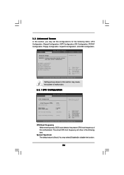
... Exit v02.54 (C) Copyright 1985-2003, American Megatrends, Inc. CPU Host Frequency While entering setup, BIOS auto detects the present CPU host frequency of this motherboard. 3.3 Advanced Screen In this section, you may set the CPU host frequency. +F1 F9 F10 ESC Select Screen Select Item Change Option General Help Load...
... Exit v02.54 (C) Copyright 1985-2003, American Megatrends, Inc. CPU Host Frequency While entering setup, BIOS auto detects the present CPU host frequency of this motherboard. 3.3 Advanced Screen In this section, you may set the CPU host frequency. +F1 F9 F10 ESC Select Screen Select Item Change Option General Help Load...

User Manual
Page 27
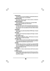
...module(s) inserted and assigns appropriate frequency automatically. Set to keep the CPU from overheated. DRAM Frequency If [Auto] is selected, the motherboard will be equal to time the CPU frequency, it requires a computer system with an Intel Pentium®4 processor that supports Hyper-...Threading technology and an operating system that includes optimization for this motherboard. If it shows "Locked", then the item Ratio CMOS Setting will be hidden. CPU Thermal Throttling You may also select other...
...module(s) inserted and assigns appropriate frequency automatically. Set to keep the CPU from overheated. DRAM Frequency If [Auto] is selected, the motherboard will be equal to time the CPU frequency, it requires a computer system with an Intel Pentium®4 processor that supports Hyper-...Threading technology and an operating system that includes optimization for this motherboard. If it shows "Locked", then the item Ratio CMOS Setting will be hidden. CPU Thermal Throttling You may also select other...
User Manual
Page 28
... default value of this feature when using ISA cards that are not PCI 2.1 compliant. 28 The default value is [Auto]. DRAM CAS# Latency Use this motherboard, you to select among [Normal] and [High] for graphics memory. DRAM Bus Selection The default value is [Auto], which will free the PCI Bus when...
... default value of this feature when using ISA cards that are not PCI 2.1 compliant. 28 The default value is [Auto]. DRAM CAS# Latency Use this motherboard, you to select among [Normal] and [High] for graphics memory. DRAM Bus Selection The default value is [Auto], which will free the PCI Bus when...

User Manual
Page 35
... Monitoring Screen In this section, it allows you to monitor the status of the hardware on your system, including the parameters of the CPU temperature, motherboard temperature, CPU fan speed, chassis fan speed, and the critical voltage.
... Monitoring Screen In this section, it allows you to monitor the status of the hardware on your system, including the parameters of the CPU temperature, motherboard temperature, CPU fan speed, chassis fan speed, and the critical voltage.

User Manual
Page 39
...in the Support CD to visit ASRock's website at http://www.asrock.com; Please install the necessary drivers to know more information. 4.2 Support CD Information The Support CD that came with the motherboard contains necessary drivers and useful utilities that the motherboard supports. Click on the file ... drivers if the system detects installed devices. or you need to contact ASRock or want to activate the devices. 4.2.3 Utilities Menu The Utilities Menu shows the applications software that enhance the motherboard features. 4.2.1 Running The Support CD To begin using the support CD,...
...in the Support CD to visit ASRock's website at http://www.asrock.com; Please install the necessary drivers to know more information. 4.2 Support CD Information The Support CD that came with the motherboard contains necessary drivers and useful utilities that the motherboard supports. Click on the file ... drivers if the system detects installed devices. or you need to contact ASRock or want to activate the devices. 4.2.3 Utilities Menu The Utilities Menu shows the applications software that enhance the motherboard features. 4.2.1 Running The Support CD To begin using the support CD,...

