
User Manual
Page 3
Exit Menu 28 3 Contents 1 Introduction 4 1.1 Package Contents 4 1.2 Specifications 5 1.3 Motherboard Layout (P4AL-8X 7 1.4 Motherboard Layout (P4AL-8XM 8 1.5 ASRock I/OTM (P4AL-8X / P4AL-8XM 9 2 Installation 10 2.1 Screw Holes 10 2.2 Pre-installation Precautions 10 2.3 CPU Installation 11 ... 20 4.1 Installing Operating System 20 4.2 Support CD Information 20 4.2.1 Running Support CD 20 4.2.2 Drivers Menu 20 4.2.3 Utilities Menu 20 4.2.4 ASRock "PC-DIY Live Demo" Program 20 4.2.5 Contact Information 20 Appendix: Advanced BIOS Setup 21 1 Advanced Menu 21 2 Security Menu 25 ...
Exit Menu 28 3 Contents 1 Introduction 4 1.1 Package Contents 4 1.2 Specifications 5 1.3 Motherboard Layout (P4AL-8X 7 1.4 Motherboard Layout (P4AL-8XM 8 1.5 ASRock I/OTM (P4AL-8X / P4AL-8XM 9 2 Installation 10 2.1 Screw Holes 10 2.2 Pre-installation Precautions 10 2.3 CPU Installation 11 ... 20 4.1 Installing Operating System 20 4.2 Support CD Information 20 4.2.1 Running Support CD 20 4.2.2 Drivers Menu 20 4.2.3 Utilities Menu 20 4.2.4 ASRock "PC-DIY Live Demo" Program 20 4.2.5 Contact Information 20 Appendix: Advanced BIOS Setup 21 1 Advanced Menu 21 2 Security Menu 25 ...

User Manual
Page 4
... on ASRock website as well. ASRock website http://www.asrock.com 1.1 Package Contents ASRock P4AL-8X motherboard (ATX form factor: 12.0" x 7.8", 30.5 x 19.8 cm) or ASRock P4AL-8XM motherboard (Micro ATX form factor: 9.6" x 7.8", 24.4 x 19.8 cm) ASRock P4AL-8X / P4AL-8XM Quick Installation Guide ASRock Intel-ALi Support CD 1 cable for IDE devices (1 x ATA 66 / 100 / 133) 1 cable for purchasing ASRock P4AL-8X / P4AL-8XM motherboard, a reliable motherboard produced under ASRock's consistently...
... on ASRock website as well. ASRock website http://www.asrock.com 1.1 Package Contents ASRock P4AL-8X motherboard (ATX form factor: 12.0" x 7.8", 30.5 x 19.8 cm) or ASRock P4AL-8XM motherboard (Micro ATX form factor: 9.6" x 7.8", 24.4 x 19.8 cm) ASRock P4AL-8X / P4AL-8XM Quick Installation Guide ASRock Intel-ALi Support CD 1 cable for IDE devices (1 x ATA 66 / 100 / 133) 1 cable for purchasing ASRock P4AL-8X / P4AL-8XM motherboard, a reliable motherboard produced under ASRock's consistently...

User Manual
Page 6
...recommended CPU bus frequencies may cause permanent damage! 4. Please check if the CPU fan on P4AL-8X / P4AL-8XM motherboard! Do NOT plug a 3.3V AGP card in the AGP slot on the motherboard functions properly before you install the PC system. 3. It may not work properly under ... legal BIOS; About the setting of the system or damage the CPU and the motherboard. 6 When the CPU frequency of P4AL-8X / P4AL-8XM is detected, the system will also be overclocked proportionally. Although P4AL-8X / P4AL-8XM offers stepless control, it is not recommended to perform over clocking. ACPI 1.1...
...recommended CPU bus frequencies may cause permanent damage! 4. Please check if the CPU fan on P4AL-8X / P4AL-8XM motherboard! Do NOT plug a 3.3V AGP card in the AGP slot on the motherboard functions properly before you install the PC system. 3. It may not work properly under ... legal BIOS; About the setting of the system or damage the CPU and the motherboard. 6 When the CPU frequency of P4AL-8X / P4AL-8XM is detected, the system will also be overclocked proportionally. Although P4AL-8X / P4AL-8XM offers stepless control, it is not recommended to perform over clocking. ACPI 1.1...

User Manual
Page 7
1.3 Motherboard Layout (P4AL-8X) 22 36 2 19.8cm (7.8 in) PS/2 1 Mouse PS2_USB_PWR1 PS/2 Keyboard CPU_FAN1 COM1 PGA478B 5 1 PARALLEL PORT ATXPWR1 DDR1 (64/72 bit, 184-pin module) DDR2 (64/... 133 26 27 25 AGP1 8 19 7 AUDIO CODEC PCI 1 Super I/O 18 2MB 11 BIOS PCI 2 ALi 16 M1563 CLRTC1 1 17 PCI 3 PCI 4 PCI 5 ` P4AL-8X USB2.0 5.1CH CMOS Battery CHA_FAN1 FLOPPY1 USB45 SPEAKER1 1 1 PANEL 1 IR1 PLED PWRBTN 1 1 HDLED RESET 9 10 13 15 14 12 1 ATX power connector (ATXPWR1) 2 CPU socket 3 ...
1.3 Motherboard Layout (P4AL-8X) 22 36 2 19.8cm (7.8 in) PS/2 1 Mouse PS2_USB_PWR1 PS/2 Keyboard CPU_FAN1 COM1 PGA478B 5 1 PARALLEL PORT ATXPWR1 DDR1 (64/72 bit, 184-pin module) DDR2 (64/... 133 26 27 25 AGP1 8 19 7 AUDIO CODEC PCI 1 Super I/O 18 2MB 11 BIOS PCI 2 ALi 16 M1563 CLRTC1 1 17 PCI 3 PCI 4 PCI 5 ` P4AL-8X USB2.0 5.1CH CMOS Battery CHA_FAN1 FLOPPY1 USB45 SPEAKER1 1 1 PANEL 1 IR1 PLED PWRBTN 1 1 HDLED RESET 9 10 13 15 14 12 1 ATX power connector (ATXPWR1) 2 CPU socket 3 ...
User Manual
Page 8
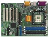
1.4 Motherboard Layout (P4AL-8XM) 22 362 4 19.8cm (7.8 in) PS/2 1 PS2_USB_PWR1 Mouse PS/2 Keyboard CPU_FAN1 COM1 PGA478B 5 1 PARALLEL PORT ATXPWR1 DDR1 (64/72 bit, 184-pin module) DDR2 (... 24 GGAAMMEE AAUUDDIIOO11 Line out LiLInnineein A8XN LAN PHY USB2.0 Chipset MMIniicc in CD1 5.1CH 23 AUX1 ` DDR400 ATA 133 20 Audio1 1 P4AL-8XM JR1 JL1 26 27 AGP 8X 25 AUDIO CODEC AGP1 19 7 8 IDE1 IDE2 CMOS Battery 2MB 11 BIOS PCI 1 Super I/O PCI 2 FLOPPY1 1 USB45 ALi M1563 CHA_FAN1 IR1 1 CLRTC1...
1.4 Motherboard Layout (P4AL-8XM) 22 362 4 19.8cm (7.8 in) PS/2 1 PS2_USB_PWR1 Mouse PS/2 Keyboard CPU_FAN1 COM1 PGA478B 5 1 PARALLEL PORT ATXPWR1 DDR1 (64/72 bit, 184-pin module) DDR2 (... 24 GGAAMMEE AAUUDDIIOO11 Line out LiLInnineein A8XN LAN PHY USB2.0 Chipset MMIniicc in CD1 5.1CH 23 AUX1 ` DDR400 ATA 133 20 Audio1 1 P4AL-8XM JR1 JL1 26 27 AGP 8X 25 AUDIO CODEC AGP1 19 7 8 IDE1 IDE2 CMOS Battery 2MB 11 BIOS PCI 1 Super I/O PCI 2 FLOPPY1 1 USB45 ALi M1563 CHA_FAN1 IR1 1 CLRTC1...

User Manual
Page 10
...wall socket before installing or removing the motherboard. Failure to do so may cause physical injuries to ensure that comes with the component. P4AL-8XM is an ATX form factor (12.0" x 7.8", 30.5 x 19.8 cm) motherboard; Failure to do so may cause ...damages to motherboard components. 2.1 Screw Holes Place screws into it on the carpet or the like. Before you handle components. 3. Before you install motherboard components or change any component. 2. Chapter 2 Installation P4AL-8X is a Micro ATX form factor (9.6" x 7.8", 24.4 x 19.8 cm) motherboard. Also remember...
...wall socket before installing or removing the motherboard. Failure to do so may cause physical injuries to ensure that comes with the component. P4AL-8XM is an ATX form factor (12.0" x 7.8", 30.5 x 19.8 cm) motherboard; Failure to do so may cause ...damages to motherboard components. 2.1 Screw Holes Place screws into it on the carpet or the like. Before you handle components. 3. Before you install motherboard components or change any component. 2. Chapter 2 Installation P4AL-8X is a Micro ATX form factor (9.6" x 7.8", 24.4 x 19.8 cm) motherboard. Also remember...

User Manual
Page 12
...Step 1. Step 3. The ASRock AGP slot has a special locking mechanism which can securely fasten the graphics card inserted. Installing an expansion card Step 1. Before installing the expansion card, read the documentation of Memory Modules (DIMM) P4AL-8X / P4AL-8XM motherboard provides three 184-pin ... the screws for the card. Align the card connector with screws. Remove the system unit cover (if your motherboard is completely seated on P4AL-8X / P4AL-8XM motherboard! 2.5 Installation of the expansion card and make sure to install expansion cards that have the 32-bit PCI ...
...Step 1. Step 3. The ASRock AGP slot has a special locking mechanism which can securely fasten the graphics card inserted. Installing an expansion card Step 1. Before installing the expansion card, read the documentation of Memory Modules (DIMM) P4AL-8X / P4AL-8XM motherboard provides three 184-pin ... the screws for the card. Align the card connector with screws. Remove the system unit cover (if your motherboard is completely seated on P4AL-8X / P4AL-8XM motherboard! 2.5 Installation of the expansion card and make sure to install expansion cards that have the 32-bit PCI ...

User Manual
Page 14
... MPEG card. 14 Connector FDD connector Figure Description (33-pin FLOPPY1) (see p.7/p.8 item 13) USB_PWR P-5 P+5 GND DUMMY 1 GND P+4 P-4 USB_PWR ASRock I/OTM provides you to the secondary IDE connector (IDE2, black). USB 2.0 header (9-pin USB45) (see p.7/p.8 item 10) Pin1 FLOPPY1 Red marking Note..., 4-pin AUX1) (CD1: see p.7/p.8 item 24) (AUX1: see p.7/p.8 item 8) PIN1 IDE1 PIN1 IDE2 Connect this BLUE end to the motherboard 80-Pin ATA 100/133 cable Connect this USB 2.0 header is available for 2 additional USB 2.0 ports. These connectors allow you 4 default USB...
... MPEG card. 14 Connector FDD connector Figure Description (33-pin FLOPPY1) (see p.7/p.8 item 13) USB_PWR P-5 P+5 GND DUMMY 1 GND P+4 P-4 USB_PWR ASRock I/OTM provides you to the secondary IDE connector (IDE2, black). USB 2.0 header (9-pin USB45) (see p.7/p.8 item 10) Pin1 FLOPPY1 Red marking Note..., 4-pin AUX1) (CD1: see p.7/p.8 item 24) (AUX1: see p.7/p.8 item 8) PIN1 IDE1 PIN1 IDE2 Connect this BLUE end to the motherboard 80-Pin ATA 100/133 cable Connect this USB 2.0 header is available for 2 additional USB 2.0 ports. These connectors allow you 4 default USB...

User Manual
Page 16
... is designed to enter the BIOS Setup after POST, restart the system by pressing + + , or by turning the system off and then back on the motherboard stores the BIOS Setup Utility. Press during the Power-On-Self-Test (POST) to enter the BIOS Setup Utility, otherwise, POST continues with their corresponding...
... is designed to enter the BIOS Setup after POST, restart the system by pressing + + , or by turning the system off and then back on the motherboard stores the BIOS Setup Utility. Press during the Power-On-Self-Test (POST) to enter the BIOS Setup Utility, otherwise, POST continues with their corresponding...
User Manual
Page 20
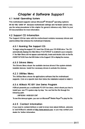
... PC-DIY live demo, which shows you need to contact ASRock or want to know more information. 4.2 Support CD Information The Support CD that came with the motherboard contains necessary drivers and useful utilities that the motherboard supports. Click on the file ASSETUP.EXE from the BIN ...you may contact your CD-ROM drive. Install the necessary drivers to your OS documentation for more about ASRock, welcome to visit ASRock's website at http://www.asrock.com; Because motherboard settings and hardware options vary, use the setup procedures in your own PC system step by step. ...
... PC-DIY live demo, which shows you need to contact ASRock or want to know more information. 4.2 Support CD Information The Support CD that came with the motherboard contains necessary drivers and useful utilities that the motherboard supports. Click on the file ASSETUP.EXE from the BIN ...you may contact your CD-ROM drive. Install the necessary drivers to your OS documentation for more about ASRock, welcome to visit ASRock's website at http://www.asrock.com; Because motherboard settings and hardware options vary, use the setup procedures in your own PC system step by step. ...
User Manual
Page 21
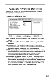
... will detect the memory module(s) inserted and assigns appropriate frequency automatically. Whether the option is open or locked is selected, the motherboard will equal the core speed of the installed motherboard. CPU Host Frequency: This shows current CPU host frequency of the installed processor. DRAM Frequency: If [Auto] is determined by the...
... will detect the memory module(s) inserted and assigns appropriate frequency automatically. Whether the option is open or locked is selected, the motherboard will equal the core speed of the installed motherboard. CPU Host Frequency: This shows current CPU host frequency of the installed processor. DRAM Frequency: If [Auto] is determined by the...

User Manual
Page 24
... select [Enable] or [Disabled] for the onboard serial ports or disable serial ports. OnBoard AC'97 Audio: Select [Disabled], [Auto] or [Enabled] for CPU temperature, Motherboard temperature, CPU fan speed, and critical voltage. It allows you to select Midi IRQ. OnBoard Serial Port: Use this onboard infrared port feature. Configuration options...
... select [Enable] or [Disabled] for the onboard serial ports or disable serial ports. OnBoard AC'97 Audio: Select [Disabled], [Auto] or [Enabled] for CPU temperature, Motherboard temperature, CPU fan speed, and critical voltage. It allows you to select Midi IRQ. OnBoard Serial Port: Use this onboard infrared port feature. Configuration options...

