User Manual
Page 5
... further notice. Chapter 3 and 4 contain the configuration guide to quality and endurance. www.asrock.com/support/index.asp 1.1 Package Contents ASRock P45X3 Deluxe Motherboard (ATX Form Factor: 12.0-in x 9.6-in, 30.5 cm x 24.4 cm) ASRock P45X3 Deluxe Quick Installation Guide ASRock P45X3 Deluxe Support CD One ASRock SLI/XFire Switch Card One 80-conductor Ultra ATA 66/100/133 IDE Ribbon Cable...
... further notice. Chapter 3 and 4 contain the configuration guide to quality and endurance. www.asrock.com/support/index.asp 1.1 Package Contents ASRock P45X3 Deluxe Motherboard (ATX Form Factor: 12.0-in x 9.6-in, 30.5 cm x 24.4 cm) ASRock P45X3 Deluxe Quick Installation Guide ASRock P45X3 Deluxe Support CD One ASRock SLI/XFire Switch Card One 80-conductor Ultra ATA 66/100/133 IDE Ribbon Cable...
User Manual
Page 8
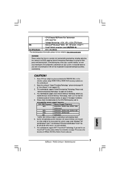
...64-bit compliant (see CAUTION 16) Certifications - FCC, CE, WHQL * For detailed product information, please visit our website: http://www.asrock.com WARNING Please realize that there is a certain risk involved with 64-bit CPU, there is operating in this situation, please adopt ...5V, +3.3V, CPU Vcore OS - Overclocking may affect your system stability, or even cause damage to the components and devices of ASRock SLI/XFire Switch Card in the BIOS, applying Untied Overclocking Technology, or using the thirdparty overclocking tools. Before you implement Dual Channel Memory ...
...64-bit compliant (see CAUTION 16) Certifications - FCC, CE, WHQL * For detailed product information, please visit our website: http://www.asrock.com WARNING Please realize that there is a certain risk involved with 64-bit CPU, there is operating in this situation, please adopt ...5V, +3.3V, CPU Vcore OS - Overclocking may affect your system stability, or even cause damage to the components and devices of ASRock SLI/XFire Switch Card in the BIOS, applying Untied Overclocking Technology, or using the thirdparty overclocking tools. Before you implement Dual Channel Memory ...
User Manual
Page 10
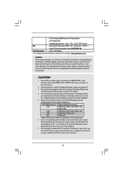
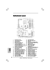
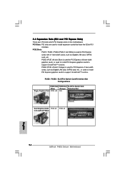
...: CTR BASS MIC IN Top: LINE IN Center: Bottom: PWR_FAN1 LAN PHY 1 CLRCMOS1 PCIE1 CMOS Battery Intel P45 Chipset Super I/O PCIE2 PCIE3 P45X3 Deluxe FSB2000 IDE1 VIA VT6330 FRONT_1394 1 IR1 1 AUDIO CODEC CD1 PCIE4 CrossFireX PCI Express 2.0 PCIE5 1394a PCI1 RoHS Debug LED 8Mb BIOS 1 HDMI_SPDIF1 ... (PWRBTN) 41 Power Fan Connector (PWR_FAN1) 20 USB 2.0 Header (USB10_11, Blue) 42 NB Fan Connector (NB_FAN1) 10 Red) 36 SLI/XFire Switch Card Retention Slot 15 Third SATAII Connector (SATAII_3; Red) 37 PCI Express x1 Slot (PCIE3) 16 Fifth SATAII Connector (SATAII_5;
...: CTR BASS MIC IN Top: LINE IN Center: Bottom: PWR_FAN1 LAN PHY 1 CLRCMOS1 PCIE1 CMOS Battery Intel P45 Chipset Super I/O PCIE2 PCIE3 P45X3 Deluxe FSB2000 IDE1 VIA VT6330 FRONT_1394 1 IR1 1 AUDIO CODEC CD1 PCIE4 CrossFireX PCI Express 2.0 PCIE5 1394a PCI1 RoHS Debug LED 8Mb BIOS 1 HDMI_SPDIF1 ... (PWRBTN) 41 Power Fan Connector (PWR_FAN1) 20 USB 2.0 Header (USB10_11, Blue) 42 NB Fan Connector (NB_FAN1) 10 Red) 36 SLI/XFire Switch Card Retention Slot 15 Third SATAII Connector (SATAII_3; Red) 37 PCI Express x1 Slot (PCIE3) 16 Fifth SATAII Connector (SATAII_5;
User Manual
Page 18
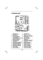
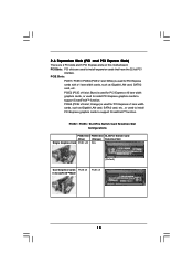
... Switch Card Retention Slot Configurations PCIE2 Slot PCIE5 Slot SLI/XFire Switch Card (Blue) (Orange) Retention Slot Single Graphics Card PCIE x16 N/A (Default) Dual Graphics Cards PCIE x8 in CrossFireXTM Mode PCIE x8 18 White) ...
... Switch Card Retention Slot Configurations PCIE2 Slot PCIE5 Slot SLI/XFire Switch Card (Blue) (Orange) Retention Slot Single Graphics Card PCIE x16 N/A (Default) Dual Graphics Cards PCIE x8 in CrossFireXTM Mode PCIE x8 18 White) ...
User Manual
Page 19
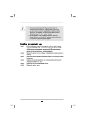
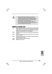
... completely seated on page 20. Keep the screws for the card before you intend to use . 1. For the information of ASRock SLI/XFire Switch Card, and please do not remove or lose ASRock SLI/XFire Switch Card when it on PCIE2 slot (Blue). Step 6. Installing an expansion card Step 1. Align the card connector with...
... completely seated on page 20. Keep the screws for the card before you intend to use . 1. For the information of ASRock SLI/XFire Switch Card, and please do not remove or lose ASRock SLI/XFire Switch Card when it on PCIE2 slot (Blue). Step 6. Installing an expansion card Step 1. Align the card connector with...
User Manual
Page 21
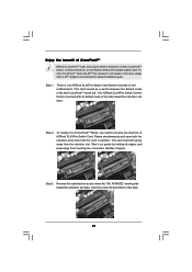
...Different CrossFireXTM cards may require different methods to have the "X8 / X8 MODE" wording side toward the retention slot base. ASRock SLI/XFire Switch Card is one ASRock SLI/XFire Switch Card factory-mounted on this motherboard. Reverse the card direction so as to enable CrossFireXTM feature. To change it... out gently by holding its default mode (x16) side toward the retention slot base. Insert the card into the bottom of ASRock SLI/XFire Switch Card. There is factory-mounted with its edges, and keep away from the retention slot. The card itself will release in...
...Different CrossFireXTM cards may require different methods to have the "X8 / X8 MODE" wording side toward the retention slot base. ASRock SLI/XFire Switch Card is one ASRock SLI/XFire Switch Card factory-mounted on this motherboard. Reverse the card direction so as to enable CrossFireXTM feature. To change it... out gently by holding its default mode (x16) side toward the retention slot base. Insert the card into the bottom of ASRock SLI/XFire Switch Card. There is factory-mounted with its edges, and keep away from the retention slot. The card itself will release in...
Quick Installation Guide
Page 2
... Clear CMOS Jumper (CLRCMOS1) 19 Power Switch (PWRBTN) 41 Power Fan Connector (PWR_FAN1) 20 USB 2.0 Header (USB10_11, Blue) 42 NB Fan Connector (NB_FAN1) 2 ASRock P45X3 Deluxe Motherboard Red) 36 SLI/XFire Switch Card Retention Slot 15 Third SATAII Connector (SATAII_3; Red) 34 Infrared Module Header (IR1) 13 Chassis Fan Connector (CHA_FAN1) 35 PCI Express...
... Clear CMOS Jumper (CLRCMOS1) 19 Power Switch (PWRBTN) 41 Power Fan Connector (PWR_FAN1) 20 USB 2.0 Header (USB10_11, Blue) 42 NB Fan Connector (NB_FAN1) 2 ASRock P45X3 Deluxe Motherboard Red) 36 SLI/XFire Switch Card Retention Slot 15 Third SATAII Connector (SATAII_3; Red) 34 Infrared Module Header (IR1) 13 Chassis Fan Connector (CHA_FAN1) 35 PCI Express...
Quick Installation Guide
Page 4
... to change without further notice. Introduction Thank you are using. www.asrock.com/support/index.asp 1.1 Package Contents ASRock P45X3 Deluxe Motherboard (ATX Form Factor: 12.0-in x 9.6-in, 30.5 cm x 24.4 cm) ASRock P45X3 Deluxe Quick Installation Guide ASRock P45X3 Deluxe Support CD One ASRock SLI/XFire Switch Card One 80-conductor Ultra ATA 66/100/133 IDE Ribbon Cable One Ribbon...
... to change without further notice. Introduction Thank you are using. www.asrock.com/support/index.asp 1.1 Package Contents ASRock P45X3 Deluxe Motherboard (ATX Form Factor: 12.0-in x 9.6-in, 30.5 cm x 24.4 cm) ASRock P45X3 Deluxe Quick Installation Guide ASRock P45X3 Deluxe Support CD One ASRock SLI/XFire Switch Card One 80-conductor Ultra ATA 66/100/133 IDE Ribbon Cable One Ribbon...
Quick Installation Guide
Page 7
...1066, DDR3 1333 1066 DDR3 800, DDR3 1066 800 DDR3 800 * DDR3 1600 memory module is no such limitation. 7. English 7 ASRock P45X3 Deluxe Motherboard Before you want to use CrossFireXTM function, please follow the instructions on page 32 for details. 4. Due to read "Untied Overclocking...12 for the CPU FSB frequency and its corresponding memory support frequency. Please read the installation guide of ASRock SLI/XFire Switch Card in the support CD. 3. This motherboard supports Dual Channel Memory Technology. CPU/Chassis/NB/Power Fan Tachometer - ...
...1066, DDR3 1333 1066 DDR3 800, DDR3 1066 800 DDR3 800 * DDR3 1600 memory module is no such limitation. 7. English 7 ASRock P45X3 Deluxe Motherboard Before you want to use CrossFireXTM function, please follow the instructions on page 32 for details. 4. Due to read "Untied Overclocking...12 for the CPU FSB frequency and its corresponding memory support frequency. Please read the installation guide of ASRock SLI/XFire Switch Card in the support CD. 3. This motherboard supports Dual Channel Memory Technology. CPU/Chassis/NB/Power Fan Tachometer - ...
Quick Installation Guide
Page 14
... the 32-bit PCI interface. PCIE2 / PCIE5 / SLI/XFire Switch Card Retention Slot Configurations PCIE2 Slot PCIE5 Slot SLI/XFire Switch Card (Blue) (Orange) Retention Slot Single Graphics Card PCIE x16 N/A (Default) Dual Graphics Cards PCIE x8 in CrossFireXTM Mode PCIE x8 English 14 ASRock P45X3 Deluxe Motherboard Blue) is used for PCI Express cards...
... the 32-bit PCI interface. PCIE2 / PCIE5 / SLI/XFire Switch Card Retention Slot Configurations PCIE2 Slot PCIE5 Slot SLI/XFire Switch Card (Blue) (Orange) Retention Slot Single Graphics Card PCIE x16 N/A (Default) Dual Graphics Cards PCIE x8 in CrossFireXTM Mode PCIE x8 English 14 ASRock P45X3 Deluxe Motherboard Blue) is used for PCI Express cards...
Quick Installation Guide
Page 15
.... Step 3. Align the card connector with screws. 1. Installing an expansion card Step 1. Please read the documentation of ASRock SLI/XFire Switch Card, and please do not remove or lose ASRock SLI/XFire Switch Card when it on PCIE2 slot (Blue). Remove the system unit cover (if your motherboard is still in... card to install only one PCI Express VGA card on this mode, you start the installation. Step 6. Replace the system cover. 15 ASRock P45X3 Deluxe Motherboard English Step 2. Step 4. If you plan to the chassis with the slot and press firmly until the card is unplugged.
.... Step 3. Align the card connector with screws. 1. Installing an expansion card Step 1. Please read the documentation of ASRock SLI/XFire Switch Card, and please do not remove or lose ASRock SLI/XFire Switch Card when it on PCIE2 slot (Blue). Remove the system unit cover (if your motherboard is still in... card to install only one PCI Express VGA card on this mode, you start the installation. Step 6. Replace the system cover. 15 ASRock P45X3 Deluxe Motherboard English Step 2. Step 4. If you plan to the chassis with the slot and press firmly until the card is unplugged.
Quick Installation Guide
Page 17
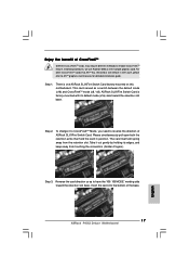
... ATITM has released or will spring away from touching the connectors (Golden Fingers). Insert the card into the bottom of ASRock SLI/XFire Switch Card. For other CrossFireXTM cards that hold the card in the future, please refer to reverse the direction ...the retention slot. Reverse the card direction so as to enable CrossFireXTM feature. ASRock SLI/XFire Switch Card is one ASRock SLI/XFire Switch Card factory-mounted on this motherboard. English 17 ASRock P45X3 Deluxe Motherboard Enjoy the benefit of CrossFireXTM Different CrossFireXTM cards may require different methods ...
... ATITM has released or will spring away from touching the connectors (Golden Fingers). Insert the card into the bottom of ASRock SLI/XFire Switch Card. For other CrossFireXTM cards that hold the card in the future, please refer to reverse the direction ...the retention slot. Reverse the card direction so as to enable CrossFireXTM feature. ASRock SLI/XFire Switch Card is one ASRock SLI/XFire Switch Card factory-mounted on this motherboard. English 17 ASRock P45X3 Deluxe Motherboard Enjoy the benefit of CrossFireXTM Different CrossFireXTM cards may require different methods ...