RAID Installation Guide
Page 2
... guide you how to create RAID on this guide carefully according to the Intel southbridge chipset that your motherboard adopts. 1. Guide to Serial ATA (SATA) Hard Disks Installation of "User Manual" in this motherboard for internal storage devices. For SATA installation guide, please refer to SATA Hard Disks Installation 1.1 Serial ATA (SATA...
... guide you how to create RAID on this guide carefully according to the Intel southbridge chipset that your motherboard adopts. 1. Guide to Serial ATA (SATA) Hard Disks Installation of "User Manual" in this motherboard for internal storage devices. For SATA installation guide, please refer to SATA Hard Disks Installation 1.1 Serial ATA (SATA...
RAID Installation Guide
Page 3
... / RAID 10 / RAID 5 settings. It will improve data access and storage since the disk array management software will introduce the basic knowledge of RAID This motherboard adopts Intel southbridge chipset that optimizes two identical hard disk drives to the entire system since it does not provide any HDDs of the same...
... / RAID 10 / RAID 5 settings. It will improve data access and storage since the disk array management software will introduce the basic knowledge of RAID This motherboard adopts Intel southbridge chipset that optimizes two identical hard disk drives to the entire system since it does not provide any HDDs of the same...
RAID Installation Guide
Page 8
... which can be lost. 4. This will be used to the SATAII port not being used . you will need another SATA / SATAII hard drive with your motherboard or after downloading it as prompted. Open the Intel Storage Utility from the Start Menu and select "Create RAID volume from Existing Hard Drive" from...
... which can be lost. 4. This will be used to the SATAII port not being used . you will need another SATA / SATAII hard drive with your motherboard or after downloading it as prompted. Open the Intel Storage Utility from the Start Menu and select "Create RAID volume from Existing Hard Drive" from...
User Manual
Page 2
... operation. This device complies with Part 15 of such damages arising from any defect or error in advance. ASRock assumes no event shall ASRock, its directors, officers, employees, or agents be liable for any indirect, special, incidental, or consequential damages...or explanation and to the contents of any interference received, including interference that may not cause harmful interference, and (2) this motherboard contains Perchlorate, a toxic substance controlled in Perchlorate Best Management Practices (BMP) regulations passed by the California Legislature. Products ...
... operation. This device complies with Part 15 of such damages arising from any defect or error in advance. ASRock assumes no event shall ASRock, its directors, officers, employees, or agents be liable for any indirect, special, incidental, or consequential damages...or explanation and to the contents of any interference received, including interference that may not cause harmful interference, and (2) this motherboard contains Perchlorate, a toxic substance controlled in Perchlorate Best Management Practices (BMP) regulations passed by the California Legislature. Products ...

User Manual
Page 3
...Table for Windows® VistaTM Premium 2008 and Basic Logo 10 1.4 Motherboard Layout (P45R2000-WiFi / P45R2000) ........ 11 1.5 Motherboard Layout (P45TurboTwins2000 12 1.6 ASRock DualLAN_SPDIF I/O (P45R2000-WiFi / P45R2000 13 1.7 ASRock SPDIF I/O Plus (P45TurboTwins2000 14 1.8 ASRock WiFi-802.11g Module Specifications (For P45R2000-WiFi Only 15 2 Installation 16 2.1 Screw Holes 16 2.2 Pre-installation ... XP / XP 64-bit / VistaTM / VistaTM 64-bit With RAID Functions (For P45R2000-WiFi / P45R2000Only 45 2.18.1 Installing Windows® XP / XP 64-bit With RAID Functions 45 2.18.2 Setting...
...Table for Windows® VistaTM Premium 2008 and Basic Logo 10 1.4 Motherboard Layout (P45R2000-WiFi / P45R2000) ........ 11 1.5 Motherboard Layout (P45TurboTwins2000 12 1.6 ASRock DualLAN_SPDIF I/O (P45R2000-WiFi / P45R2000 13 1.7 ASRock SPDIF I/O Plus (P45TurboTwins2000 14 1.8 ASRock WiFi-802.11g Module Specifications (For P45R2000-WiFi Only 15 2 Installation 16 2.1 Screw Holes 16 2.2 Pre-installation ... XP / XP 64-bit / VistaTM / VistaTM 64-bit With RAID Functions (For P45R2000-WiFi / P45R2000Only 45 2.18.1 Installing Windows® XP / XP 64-bit With RAID Functions 45 2.18.2 Setting...

User Manual
Page 5
... Contents ASRock P45R2000-WiFi / P45R2000 / P45TurboTwins2000 Motherboard (ATX Form Factor: 12.0-in x 9.6-in, 30.5 cm x 24.4 cm) ASRock P45R2000-WiFi / P45R2000 / P45TurboTwins2000 Quick Installation Guide ASRock P45R2000-WiFi / P45R2000 / P45TurboTwins2000 Support CD ASRock WiFi-802.11g Module Operation Guide (For P45R2000-WiFi Only) Motherboard Accessories One ASRock SLI/XFire Switch Card One 80-conductor Ultra ATA 66/100/133 IDE Ribbon Cable One Ribbon Cable for purchasing ASRock P45R2000-WiFi / P45R2000 / P45TurboTwins2000 motherboard, a reliable motherboard...
... Contents ASRock P45R2000-WiFi / P45R2000 / P45TurboTwins2000 Motherboard (ATX Form Factor: 12.0-in x 9.6-in, 30.5 cm x 24.4 cm) ASRock P45R2000-WiFi / P45R2000 / P45TurboTwins2000 Quick Installation Guide ASRock P45R2000-WiFi / P45R2000 / P45TurboTwins2000 Support CD ASRock WiFi-802.11g Module Operation Guide (For P45R2000-WiFi Only) Motherboard Accessories One ASRock SLI/XFire Switch Card One 80-conductor Ultra ATA 66/100/133 IDE Ribbon Cable One Ribbon Cable for purchasing ASRock P45R2000-WiFi / P45R2000 / P45TurboTwins2000 motherboard, a reliable motherboard...

User Manual
Page 9
...reverse the direction of ASRock SLI/XFire Switch Card in this situation, please adopt DDR3 1333 memory modules on page 13 and 14 for details about eSATAII and eSATAII installation procedures. 11. For microphone input, this motherboard. Power Management for system...XP SP1 or SP2 / 2000 SP4. 9 Please read "eSATAII Interface Introduction" on page 53 for proper jumper settings. 2. This motherboard supports ATITM CrossFireTM technology. Please read "Untied Overclocking Technology" on page 37 for proper connection. 9. Before you want to use CrossFireTM ...
...reverse the direction of ASRock SLI/XFire Switch Card in this situation, please adopt DDR3 1333 memory modules on page 13 and 14 for details about eSATAII and eSATAII installation procedures. 11. For microphone input, this motherboard. Power Management for system...XP SP1 or SP2 / 2000 SP4. 9 Please read "eSATAII Interface Introduction" on page 53 for proper jumper settings. 2. This motherboard supports ATITM CrossFireTM technology. Please read "Untied Overclocking Technology" on page 37 for proper connection. 9. Before you want to use CrossFireTM ...
User Manual
Page 10
... over-clocking. Please visit our website for minimum hardware requirements. Although this motherboard and plan to qualify for the operation procedures of ASRock WiFi-802.11g or WiFi-802.11n module. It is detected, the system will automatically shutdown. ASRock website: http://www.asrock.com 14. To improve heat dissipation, remember to create a wireless environment and...
... over-clocking. Please visit our website for minimum hardware requirements. Although this motherboard and plan to qualify for the operation procedures of ASRock WiFi-802.11g or WiFi-802.11n module. It is detected, the system will automatically shutdown. ASRock website: http://www.asrock.com 14. To improve heat dissipation, remember to create a wireless environment and...

User Manual
Page 11
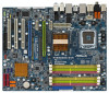
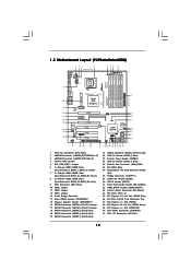
... Header (FRONT_1394) 28 DeskExpress Hot Plug Detection Header (IR1) 29 Floppy Connector (FLOPPY1) 30 COM Port Header (COM1) 31 WiFi/E Header (WIFI/E) 32 Front Panel Audio Header (HD_AUDIO1) 33 HDMI_SPDIF Header (HDMI_SPDIF1) 34 Internal Audio Connector: CD1 (Black) 35 PCI Slots ... Slot (PCIE2, Green) 40 PCI Express x1 Slot (PCIE1/DE) 41 ATX Power Connector (ATXPWR1) 42 ATX 12V Connector (ATX12V1) 11 1.4 Motherboard Layout (P45R2000-WiFi / P45R2000) 1 23 4 24.4cm (9.6 in) 5 67 8 PS2 Mouse PS2 Keyboard Coaxial SPDIF Optical SPDIF CPU_FAN1 eSATAII_BOTTOM (Port 5) eSATAII_TOP (Port 4)...
... Header (FRONT_1394) 28 DeskExpress Hot Plug Detection Header (IR1) 29 Floppy Connector (FLOPPY1) 30 COM Port Header (COM1) 31 WiFi/E Header (WIFI/E) 32 Front Panel Audio Header (HD_AUDIO1) 33 HDMI_SPDIF Header (HDMI_SPDIF1) 34 Internal Audio Connector: CD1 (Black) 35 PCI Slots ... Slot (PCIE2, Green) 40 PCI Express x1 Slot (PCIE1/DE) 41 ATX Power Connector (ATXPWR1) 42 ATX 12V Connector (ATX12V1) 11 1.4 Motherboard Layout (P45R2000-WiFi / P45R2000) 1 23 4 24.4cm (9.6 in) 5 67 8 PS2 Mouse PS2 Keyboard Coaxial SPDIF Optical SPDIF CPU_FAN1 eSATAII_BOTTOM (Port 5) eSATAII_TOP (Port 4)...
User Manual
Page 12
...26 SPI BIOS Chip 27 DeskExpress Hot Plug Detection Header (IR1) 28 Floppy Connector (FLOPPY1) 29 COM Port Header (COM1) 30 WiFi/E Header (WIFI/E) 31 Front Panel Audio Header (HD_AUDIO1) 32 HDMI_SPDIF Header (HDMI_SPDIF1) 33 Internal Audio Connector: CD1 (Black) 34 PCI Slots (...ATX Power Connector (ATXPWR1) 41 ATX 12V Connector (ATX12V1) 12 Yellow) 7 2 x 240-pin DDR3 DIMM Slots (Dual Channel B: DDR3_A1, DDR3_B1; 1.5 Motherboard Layout (P45TurboTwins2000) 1 23 4 24.4cm (9.6 in) CPU_FAN1 eSATAII_BOTTOM (Port 5) eSATAII_TOP (Port 4) 5 67 8 1 PS2_USB_PWR1 PS2 Mouse PS2 Keyboard Coaxial ...
...26 SPI BIOS Chip 27 DeskExpress Hot Plug Detection Header (IR1) 28 Floppy Connector (FLOPPY1) 29 COM Port Header (COM1) 30 WiFi/E Header (WIFI/E) 31 Front Panel Audio Header (HD_AUDIO1) 32 HDMI_SPDIF Header (HDMI_SPDIF1) 33 Internal Audio Connector: CD1 (Black) 34 PCI Slots (...ATX Power Connector (ATXPWR1) 41 ATX 12V Connector (ATX12V1) 12 Yellow) 7 2 x 240-pin DDR3 DIMM Slots (Dual Channel B: DDR3_A1, DDR3_B1; 1.5 Motherboard Layout (P45TurboTwins2000) 1 23 4 24.4cm (9.6 in) CPU_FAN1 eSATAII_BOTTOM (Port 5) eSATAII_TOP (Port 4) 5 67 8 1 PS2_USB_PWR1 PS2 Mouse PS2 Keyboard Coaxial ...

User Manual
Page 15
... (30m) Outdoor: 200ft (60m) * The range varies in the following path of ASRock motherboard support CD: ..\ ASRock WiFi-802.11g \ Vista64_Vista_XP64_XP 15 1.8 ASRock WiFi-802.11g Module Specifications (For P45R2000-WiFi Only) ASRock WiFi-802.11g module is an easy-to-use ASRock WiFi-802.11g module on this motherboard, please carefully read the document in different environments Number of - Station mode: Infrastructure...
... (30m) Outdoor: 200ft (60m) * The range varies in the following path of ASRock motherboard support CD: ..\ ASRock WiFi-802.11g \ Vista64_Vista_XP64_XP 15 1.8 ASRock WiFi-802.11g Module Specifications (For P45R2000-WiFi Only) ASRock WiFi-802.11g module is an easy-to-use ASRock WiFi-802.11g module on this motherboard, please carefully read the document in different environments Number of - Station mode: Infrastructure...

User Manual
Page 16
...cord is an ATX form factor (12.0" x 9.6", 30.5 x 24.4 cm) motherboard. Before you install the motherboard, study the configuration of the following precautions before installing or removing the motherboard. To avoid damaging the motherboard components due to the chassis. Hold components by circles to secure the... safety grounded object before touching any component. 2. Also remember to unplug the power cord before you and damages to motherboard components. 2.1 Screw Holes Place screws into it on the carpet or the like. Doing so may cause physical injuries to you install...
...cord is an ATX form factor (12.0" x 9.6", 30.5 x 24.4 cm) motherboard. Before you install the motherboard, study the configuration of the following precautions before installing or removing the motherboard. To avoid damaging the motherboard components due to the chassis. Hold components by circles to secure the... safety grounded object before touching any component. 2. Also remember to unplug the power cord before you and damages to motherboard components. 2.1 Screw Holes Place screws into it on the carpet or the like. Doing so may cause physical injuries to you install...

User Manual
Page 18
.... Step 4-2. Step 4. Close the socket: Step 4-1. While pressing down lightly on center of load lever. 18 Step 2-4. This cap must be placed if returning the motherboard for after service.
.... Step 4-2. Step 4. Close the socket: Step 4-1. While pressing down lightly on center of load lever. 18 Step 2-4. This cap must be placed if returning the motherboard for after service.
User Manual
Page 19
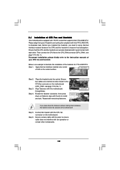
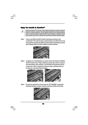
...No. 1). Step 4. Repeat with fan operation or contact other . Step 1. Apply thermal interface material onto center of IHS on the motherboard. Secure excess cable with tie-wrap to ensure cable does not interfere with remaining fasteners. Before you installed the heatsink, you press down ...kindly refer to improve heat dissipation. Align fasteners with each other components. 19 Step 5. 2.4 Installation of CPU Fan and Heatsink This motherboard is an example to illustrate the installation of the heatsink for 775-LAND CPU. Rotate the fastener clockwise, then press down the ...
...No. 1). Step 4. Repeat with fan operation or contact other . Step 1. Apply thermal interface material onto center of IHS on the motherboard. Secure excess cable with tie-wrap to ensure cable does not interfere with remaining fasteners. Before you installed the heatsink, you press down ...kindly refer to improve heat dissipation. Align fasteners with each other components. 19 Step 5. 2.4 Installation of CPU Fan and Heatsink This motherboard is an example to illustrate the installation of the heatsink for 775-LAND CPU. Rotate the fastener clockwise, then press down the ...
User Manual
Page 20
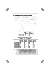
...4 memory modules DS DDR3_A2 (Pink Slot) X X SS DS SS DS DDR3_B1 (Green Slot) SS DS X X SS DS DDR3_B2 (Pink Slot) X X SS DS SS DS 1. This motherboard also allows you have to install identical DDR2 DIMM pair in the set of green slots (DDR3_A1 and DDR3_B1), or in Dual Channel A (DDRII_1 and... is recommended to install identical (the same brand, speed, size and chip-type) DDR2/DDR3 DIMM pair in the slots of Memory Modules (DIMM) This motherboard provides two 240-pin DDR2 (Double Data Rate 2) DIMM slots and four 240-pin DDR3 (Double Data Rate 3) DIMM slots, and supports Dual Channel Memory...
...4 memory modules DS DDR3_A2 (Pink Slot) X X SS DS SS DS DDR3_B1 (Green Slot) SS DS X X SS DS DDR3_B2 (Pink Slot) X X SS DS SS DS 1. This motherboard also allows you have to install identical DDR2 DIMM pair in the set of green slots (DDR3_A1 and DDR3_B1), or in Dual Channel A (DDRII_1 and... is recommended to install identical (the same brand, speed, size and chip-type) DDR2/DDR3 DIMM pair in the slots of Memory Modules (DIMM) This motherboard provides two 240-pin DDR2 (Double Data Rate 2) DIMM slots and four 240-pin DDR3 (Double Data Rate 3) DIMM slots, and supports Dual Channel Memory...
User Manual
Page 21
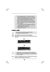
...2. Step 3. Firmly insert the DIMM into the slot until the retaining clips at both ends fully snap back in DDR3 DIMM slots on this motherboard at incorrect orientation. notch break notch break The DIMM only fits in DDR2 DIMM slots on the slot. If only one correct orientation. It ...DDR2 and DDR3 memory modules cannot be damaged. 5. Align a DIMM on the slot such that the notch on the DIMM matches the break on this motherboard, it is properly seated. 21 Installing a DIMM Please make sure to install a DDR3 memory module into DDR2 slot or install a DDR2 memory module into...
...2. Step 3. Firmly insert the DIMM into the slot until the retaining clips at both ends fully snap back in DDR3 DIMM slots on this motherboard at incorrect orientation. notch break notch break The DIMM only fits in DDR2 DIMM slots on the slot. If only one correct orientation. It ...DDR2 and DDR3 memory modules cannot be damaged. 5. Align a DIMM on the slot such that the notch on the DIMM matches the break on this motherboard, it is properly seated. 21 Installing a DIMM Please make sure to install a DDR3 memory module into DDR2 slot or install a DDR2 memory module into...

User Manual
Page 22
..., or used to install PCI Express graphics cards to support CrossFireTM function. PCI Slots: PCI slots are 3 PCI slots and 4 PCI Express slots on this motherboard. PCIE3 (PCIE x1 slot; PCIE2 / PCIE4 / SLI/XFire Switch Card Retention Slot Configurations Single Graphics Card PCIE2 Slot PCIE4 Slot (Green) (Blue) PCIE... LAN card, SATA2 card, etc., or used for PCI Express cards with x1 lane width cards, such as Gigabit LAN card, SATA2 card and ASRock PCIE_DE card. PCIE4 (PCIE x16 slot; 2.6 Expansion Slots (PCI and PCI Express Slots) There are used for PCI Express cards with x1 lane...
..., or used to install PCI Express graphics cards to support CrossFireTM function. PCI Slots: PCI slots are 3 PCI slots and 4 PCI Express slots on this motherboard. PCIE3 (PCIE x1 slot; PCIE2 / PCIE4 / SLI/XFire Switch Card Retention Slot Configurations Single Graphics Card PCIE2 Slot PCIE4 Slot (Green) (Blue) PCIE... LAN card, SATA2 card, etc., or used for PCI Express cards with x1 lane width cards, such as Gigabit LAN card, SATA2 card and ASRock PCIE_DE card. PCIE4 (PCIE x16 slot; 2.6 Expansion Slots (PCI and PCI Express Slots) There are used for PCI Express cards with x1 lane...

User Manual
Page 23
...cards and CrossFireTM setup procedures, please refer to use. Before installing the expansion card, please make necessary hardware settings for later use ASRock DeskExpress function on this motherboard, please install it is unplugged. Remove the bracket facing the slot that the power supply is switched off or the power cord is...1. Installing an expansion card Step 1. Step 2. Keep the screws for the card before you want to install only one PCI Express VGA card on this motherboard, please install ASRock PCIE_DE card on page 24. 3. Step 6. Replace the system cover. 23
...cards and CrossFireTM setup procedures, please refer to use. Before installing the expansion card, please make necessary hardware settings for later use ASRock DeskExpress function on this motherboard, please install it is unplugged. Remove the bracket facing the slot that the power supply is switched off or the power cord is...1. Installing an expansion card Step 1. Step 2. Keep the screws for the card before you want to install only one PCI Express VGA card on this motherboard, please install ASRock PCIE_DE card on page 24. 3. Step 6. Replace the system cover. 23
User Manual
Page 24
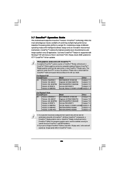
... the highest possible level of CrossFireTM. If you install. 2.7 CrossFireTM Operation Guide This motherboard supports CrossFireTM feature. A complete CrossFireTM system requires a CrossFireTM Ready motherboard, a CrossFireTM Edition graphics card and a compatible standard Radeon (CrossFireTM Ready) graphics card...benefit from the CrossFireTM multi-GPU platform. 2. All three CrossFireTM components, a CrossFireTM Ready graphics card, a CrossFireTM Ready motherboard and a CrossFireTM Edition co-processor graphics card, must be installed correctly to cards from the same series, or two...
... the highest possible level of CrossFireTM. If you install. 2.7 CrossFireTM Operation Guide This motherboard supports CrossFireTM feature. A complete CrossFireTM system requires a CrossFireTM Ready motherboard, a CrossFireTM Edition graphics card and a compatible standard Radeon (CrossFireTM Ready) graphics card...benefit from the CrossFireTM multi-GPU platform. 2. All three CrossFireTM components, a CrossFireTM Ready graphics card, a CrossFireTM Ready motherboard and a CrossFireTM Edition co-processor graphics card, must be installed correctly to cards from the same series, or two...
User Manual
Page 25
... the default mode (x16) and CrossFire mode (x8 / x8). Insert the card into the bottom of ASRock SLI/XFire Switch Card. ASRock SLI/XFire Switch Card is one ASRock SLI/XFire Switch Card factory-mounted on this motherboard. Enjoy the benefit of CrossFireTM Different CrossFireTM cards may require different methods to reverse the direction...
... the default mode (x16) and CrossFire mode (x8 / x8). Insert the card into the bottom of ASRock SLI/XFire Switch Card. ASRock SLI/XFire Switch Card is one ASRock SLI/XFire Switch Card factory-mounted on this motherboard. Enjoy the benefit of CrossFireTM Different CrossFireTM cards may require different methods to reverse the direction...

