RAID Installation Guide
Page 2
..., including RAID 0, RAID 1, RAID 10, RAID 5, and Intel Matrix Storage. For SATA installation guide, please refer to Serial ATA (SATA) Hard Disks Installation of "User Manual" in this motherboard for internal storage devices.
..., including RAID 0, RAID 1, RAID 10, RAID 5, and Intel Matrix Storage. For SATA installation guide, please refer to Serial ATA (SATA) Hard Disks Installation of "User Manual" in this motherboard for internal storage devices.

User Manual
Page 1
All rights reserved. 1 P45R2000-WiFi / P45R2000 / P45TurboTwins2000 User Manual Version 1.1 Published September 2008 Copyright©2008 ASRock INC.
All rights reserved. 1 P45R2000-WiFi / P45R2000 / P45TurboTwins2000 User Manual Version 1.1 Published September 2008 Copyright©2008 ASRock INC.
User Manual
Page 2
...in any form or by the California Legislature. ASRock assumes no event shall ASRock, its directors, officers, employees, or agents be constructed as a commitment by the purchaser for identification or explanation and to the contents of this manual, ASRock does not provide warranty of any defect or... error in the manual or product. With respect to the owners' benefit, without notice, and should not be liable for ...
...in any form or by the California Legislature. ASRock assumes no event shall ASRock, its directors, officers, employees, or agents be constructed as a commitment by the purchaser for identification or explanation and to the contents of this manual, ASRock does not provide warranty of any defect or... error in the manual or product. With respect to the owners' benefit, without notice, and should not be liable for ...

User Manual
Page 5
...) ASRock P45R2000-WiFi / P45R2000 / P45TurboTwins2000 Quick Installation Guide ASRock P45R2000-WiFi / P45R2000 / P45TurboTwins2000 Support CD ASRock WiFi-802.11g Module Operation Guide (For P45R2000-WiFi Only) Motherboard Accessories One ASRock SLI/XFire Switch Card One 80-conductor Ultra ATA 66/100/133 IDE Ribbon Cable One Ribbon Cable for purchasing ASRock P45R2000-WiFi / P45R2000 / P45TurboTwins2000 motherboard, a reliable motherboard produced under ASRock's consistently stringent quality control. In this manual will...
...) ASRock P45R2000-WiFi / P45R2000 / P45TurboTwins2000 Quick Installation Guide ASRock P45R2000-WiFi / P45R2000 / P45TurboTwins2000 Support CD ASRock WiFi-802.11g Module Operation Guide (For P45R2000-WiFi Only) Motherboard Accessories One ASRock SLI/XFire Switch Card One 80-conductor Ultra ATA 66/100/133 IDE Ribbon Cable One Ribbon Cable for purchasing ASRock P45R2000-WiFi / P45R2000 / P45TurboTwins2000 motherboard, a reliable motherboard produced under ASRock's consistently stringent quality control. In this manual will...
User Manual
Page 19
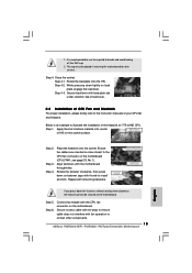
Please adopt the type of heatsink and cooling fan compliant with Intel 775-LAND CPU to the instruction manuals of your CPU fan and heatsink. For proper installation, please kindly refer to dissipate heat. Repeat with the CPU fan connector on the motherboard. If ...
Please adopt the type of heatsink and cooling fan compliant with Intel 775-LAND CPU to the instruction manuals of your CPU fan and heatsink. For proper installation, please kindly refer to dissipate heat. Repeat with the CPU fan connector on the motherboard. If ...
User Manual
Page 25
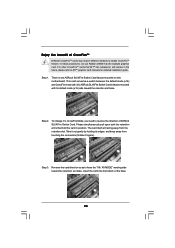
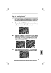
...retention slot base. This card served as the example graphics card. Step 2. Take it to CrossFire Mode, you need to ATITM graphics card manuals for detailed installation guide. Enjoy the benefit of CrossFireTM Different CrossFireTM cards may require different methods to have the "X8 / X8 MODE" ...other CrossFireTM cards that hold the card in the future, please refer to reverse the direction of the base. 25 ASRock SLI/XFire Switch Card is one ASRock SLI/XFire Switch Card factory-mounted on this motherboard. The card itself will release in position. Insert the card into...
...retention slot base. This card served as the example graphics card. Step 2. Take it to CrossFire Mode, you need to ATITM graphics card manuals for detailed installation guide. Enjoy the benefit of CrossFireTM Different CrossFireTM cards may require different methods to have the "X8 / X8 MODE" ...other CrossFireTM cards that hold the card in the future, please refer to reverse the direction of the base. 25 ASRock SLI/XFire Switch Card is one ASRock SLI/XFire Switch Card factory-mounted on this motherboard. The card itself will release in position. Insert the card into...
User Manual
Page 33
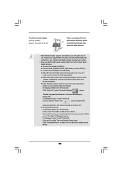
... is an interface for HD audio panel only. Click the icon on the chassis must support HDA to the "Front Mic" Tab in our manual and chassis manual to hear your system. 2. Please follow the instruction in the Realtek Control panel. MIC_RET and OUT_RET are for front panel audio cable that allows...
... is an interface for HD audio panel only. Click the icon on the chassis must support HDA to the "Front Mic" Tab in our manual and chassis manual to hear your system. 2. Please follow the instruction in the Realtek Control panel. MIC_RET and OUT_RET are for front panel audio cable that allows...
User Manual
Page 36
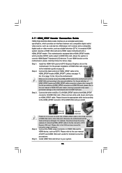
...pin) on this motherboard and the HDMI VGA card. For the pin definition of HDMI_SPDIF header and HDMI_SPDIF cable connectors, please refer to the user manual of HDMI VGA card vendor. For the pin definition of HDMI_SPDIF connectors on the motherboard. white end (2-pin) (B) white end (3-pin) (C) ...Step 4. Please do not connect the white end of HDMI_SPDIF cable to the VGA card user manual for detailed connection procedures. Please refer to the wrong connector of HDMI VGA card or other VGA card. A complete HDMI system requires a HDMI VGA...
...pin) on this motherboard and the HDMI VGA card. For the pin definition of HDMI_SPDIF header and HDMI_SPDIF cable connectors, please refer to the user manual of HDMI VGA card vendor. For the pin definition of HDMI_SPDIF connectors on the motherboard. white end (2-pin) (B) white end (3-pin) (C) ...Step 4. Please do not connect the white end of HDMI_SPDIF cable to the VGA card user manual for detailed connection procedures. Please refer to the wrong connector of HDMI VGA card or other VGA card. A complete HDMI system requires a HDMI VGA...
User Manual
Page 43
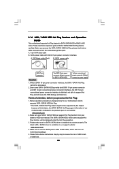
... HDD can support Hot Plug function from the motherboard gift box pack. Please make sure the SATA / SATAII driver is available on our website: www.asrock.com 2. A. 7-pin SATA data cable B. SATA power cable SATA 7-pin connector The SATA 15-pin power connector (Black) connect to SATA /... interface is designed only for SATA / SATAII HDD in the product spec on our support website: www.asrock.com 4. Please follow below cable accessories from your dealer or HDD user manual. 2.16 SATA / SATAII HDD Hot Plug Feature and Operation Guide This motherboard supports Hot Plug feature for...
... HDD can support Hot Plug function from the motherboard gift box pack. Please make sure the SATA / SATAII driver is available on our website: www.asrock.com 2. A. 7-pin SATA data cable B. SATA power cable SATA 7-pin connector The SATA 15-pin power connector (Black) connect to SATA /... interface is designed only for SATA / SATAII HDD in the product spec on our support website: www.asrock.com 4. Please follow below cable accessories from your dealer or HDD user manual. 2.16 SATA / SATAII HDD Hot Plug Feature and Operation Guide This motherboard supports Hot Plug feature for...
User Manual
Page 53
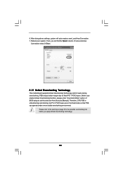
... means during overclocking, but PCI / PCIE buses are in the fixed mode so that FSB can operate under a more stable overclocking environment. Please refer to [Manual]. Then, you will auto create a new Local Area Connection. 7. Therefore, CPU FSB is untied during overclocking, FSB enjoys better margin due to fixed PCI / PCIE...
... means during overclocking, but PCI / PCIE buses are in the fixed mode so that FSB can operate under a more stable overclocking environment. Please refer to [Manual]. Then, you will auto create a new Local Area Connection. 7. Therefore, CPU FSB is untied during overclocking, FSB enjoys better margin due to fixed PCI / PCIE...
User Manual
Page 58
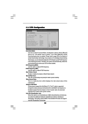
... [I .O.T.] (Intelligent Overclocking Technology), you select [Manual], Untied Overclocking function is heavy loaded. Boot Failure Guard Enable or disable the feature of this motherboard. The C1 state is [Auto]. Please refer to ...
... [I .O.T.] (Intelligent Overclocking Technology), you select [Manual], Untied Overclocking function is heavy loaded. Boot Failure Guard Enable or disable the feature of this motherboard. The C1 state is [Auto]. Please refer to ...

User Manual
Page 62
...this to enable or disable CD-In of this to enable or disable the "OnBoard Lan 2" feature. Configuration options: [Auto] and [Manual]. CD-In This option is [Auto]. 62 Use this option. OnBoard Lan 1 This allows you plan to use this to enable ...], [2.02V], [2.08V], [2.14V], [2.20V], [2.31V], [2.37V], [2.42V], [2.48V], [2.54V], [2.60V], [2.66V] and [2.72V]. SB Core Voltage Use this feature is for P45R2000-WiFi / P45R2000 only. The default value of OnBoard HD Audio. OnBoard Lan 2 This allows you to select NB Core Voltage. OnBoard 1394 This option is [Auto]. DRAM...
...this to enable or disable CD-In of this to enable or disable the "OnBoard Lan 2" feature. Configuration options: [Auto] and [Manual]. CD-In This option is [Auto]. 62 Use this option. OnBoard Lan 1 This allows you plan to use this to enable ...], [2.02V], [2.08V], [2.14V], [2.20V], [2.31V], [2.37V], [2.42V], [2.48V], [2.54V], [2.60V], [2.66V] and [2.72V]. SB Core Voltage Use this feature is for P45R2000-WiFi / P45R2000 only. The default value of OnBoard HD Audio. OnBoard Lan 2 This allows you to select NB Core Voltage. OnBoard 1394 This option is [Auto]. DRAM...
Quick Installation Guide
Page 7
... user manual presented in Floppy Drive Four Serial ATA (SATA) Data Cables (Optional) One Serial ATA (SATA) HDD Power Cable (Optional) One HDMI_SPDIF Cable (Optional) One "ASRock DualLAN_SPDIF I/O" I/O Panel Shield (P45R2000-WiFi / P45R2000) One "ASRock SPDIF I/O Plus" I/O Panel Shield (P45TurboTwins2000) WiFi Accessories (For P45R2000-WiFi Only) One ASRock WiFi-802.11g Module One Antenna One WiFi Bracket 7 ASRock P45R2000-WiFi / P45R2000 / P45TurboTwins2000 Motherboard English www.asrock.com...
... user manual presented in Floppy Drive Four Serial ATA (SATA) Data Cables (Optional) One Serial ATA (SATA) HDD Power Cable (Optional) One HDMI_SPDIF Cable (Optional) One "ASRock DualLAN_SPDIF I/O" I/O Panel Shield (P45R2000-WiFi / P45R2000) One "ASRock SPDIF I/O Plus" I/O Panel Shield (P45TurboTwins2000) WiFi Accessories (For P45R2000-WiFi Only) One ASRock WiFi-802.11g Module One Antenna One WiFi Bracket 7 ASRock P45R2000-WiFi / P45R2000 / P45TurboTwins2000 Motherboard English www.asrock.com...

Quick Installation Guide
Page 11
...VistaTM. For audio output, this motherboard supports both stereo and mono modes. English 11 ASRock P45R2000-WiFi / P45R2000 / P45TurboTwins2000 Motherboard CAUTION! 1. Please read the installation guide of ASRock SLI/XFire Switch Card in this motherboard. If you implement Dual Channel Memory Technology,...native FSB1600/1333/1066/ 800 MHz. About the setting of "Hyper Threading Technology", please check page 55 of "User Manual" in the support CD. 3. This motherboard supports Dual Channel Memory Technology. This motherboard supports Untied Overclocking Technology. Please...
...VistaTM. For audio output, this motherboard supports both stereo and mono modes. English 11 ASRock P45R2000-WiFi / P45R2000 / P45TurboTwins2000 Motherboard CAUTION! 1. Please read the installation guide of ASRock SLI/XFire Switch Card in this motherboard. If you implement Dual Channel Memory Technology,...native FSB1600/1333/1066/ 800 MHz. About the setting of "Hyper Threading Technology", please check page 55 of "User Manual" in the support CD. 3. This motherboard supports Dual Channel Memory Technology. This motherboard supports Untied Overclocking Technology. Please...

Quick Installation Guide
Page 12
... wireless local area network (WLAN) adapter. Although this motherboard and plan to page 61 of "User Manual" in order to -use IDE mode under Windows® environment. English 12 ASRock P45R2000-WiFi / P45R2000 / P45TurboTwins2000 Motherboard ASRock website http://www.asrock.com 13. Please refer to submit Windows® VistaTM Premium 2008 and Basic logo, please follow below...
... wireless local area network (WLAN) adapter. Although this motherboard and plan to page 61 of "User Manual" in order to -use IDE mode under Windows® environment. English 12 ASRock P45R2000-WiFi / P45R2000 / P45TurboTwins2000 Motherboard ASRock website http://www.asrock.com 13. Please refer to submit Windows® VistaTM Premium 2008 and Basic logo, please follow below...
Quick Installation Guide
Page 15
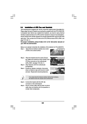
...side closest to ensure cable does not interfere with the motherboard throughholes. Align fasteners with fan operation or contact other components. 15 ASRock P45R2000-WiFi / P45R2000 / P45TurboTwins2000 Motherboard English Step 5. Secure excess cable with tie-wrap to the CPU fan connector on load plate, engage the load...775-LAND CPU. Place the heatsink onto the socket. Step 6. 1. Below is recommended to use the cap tab to the instruction manuals of IHS on the motherboard. Step 4-2. Repeat with load plate tab under retention tab of load lever. 2.2 Installation of CPU Fan...
...side closest to ensure cable does not interfere with the motherboard throughholes. Align fasteners with fan operation or contact other components. 15 ASRock P45R2000-WiFi / P45R2000 / P45TurboTwins2000 Motherboard English Step 5. Secure excess cable with tie-wrap to the CPU fan connector on load plate, engage the load...775-LAND CPU. Place the heatsink onto the socket. Step 6. 1. Below is recommended to use the cap tab to the instruction manuals of IHS on the motherboard. Step 4-2. Repeat with load plate tab under retention tab of load lever. 2.2 Installation of CPU Fan...
Quick Installation Guide
Page 21
...the "X8 / X8 MODE" wording side toward the retention slot base. Insert the card into the bottom of the base. 21 ASRock P45R2000-WiFi / P45R2000 / P45TurboTwins2000 Motherboard Step 1. Step 2. In below procedures, we use Radeon 2600XT as a switch between the default mode (x16) ...ASRock SLI/XFire Switch Card factory-mounted on this motherboard. This card served as the example graphics card. The card itself will release in position. English Step 3. Enjoy the benefit of CrossFireTM Different CrossFireTM cards may require different methods to ATITM graphics card manuals...
...the "X8 / X8 MODE" wording side toward the retention slot base. Insert the card into the bottom of the base. 21 ASRock P45R2000-WiFi / P45R2000 / P45TurboTwins2000 Motherboard Step 1. Step 2. In below procedures, we use Radeon 2600XT as a switch between the default mode (x16) ...ASRock SLI/XFire Switch Card factory-mounted on this motherboard. This card served as the example graphics card. The card itself will release in position. English Step 3. Enjoy the benefit of CrossFireTM Different CrossFireTM cards may require different methods to ATITM graphics card manuals...
Quick Installation Guide
Page 29
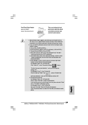
... mic, please deselect "Mute" icon in our manual and chassis manual to the front panel audio header as below: A. Please follow the instruction in "Front Mic" of audio devices. 1. Connect Ground (GND) to [Enabled]. E. F. MIC_RET and OUT_RET are for AC'97 audio panel. English 29 ASRock P45R2000-WiFi / P45R2000 / P45TurboTwins2000 Motherboard Connect Audio_R (RIN) to OUT2_R...
... mic, please deselect "Mute" icon in our manual and chassis manual to the front panel audio header as below: A. Please follow the instruction in "Front Mic" of audio devices. 1. Connect Ground (GND) to [Enabled]. E. F. MIC_RET and OUT_RET are for AC'97 audio panel. English 29 ASRock P45R2000-WiFi / P45R2000 / P45TurboTwins2000 Motherboard Connect Audio_R (RIN) to OUT2_R...

Quick Installation Guide
Page 32
English SATAII connectors (SATAII_5 (Port4) and SATAII_6 (Port5)) eSATAII connectors (eSATAII_TOP (Port4) and eSATAII_BOTTOM (Port5)) 32 ASRock P45R2000-WiFi / P45R2000 / P45TurboTwins2000 Motherboard This motherboard is equipped with eSATAII devices. Please refer to page 35 to 37 for detailed installation procedures. 2.... or remove your eSATAII devices to the eSATAII ports only when the system is power-off. 3. How to page 36 of "User Manual" in the support CD for detailed information of RAID mode, IDE mode, and AHCI mode. 2.9 HDMI_SPDIF Header Connection Guide HDMI (High...
English SATAII connectors (SATAII_5 (Port4) and SATAII_6 (Port5)) eSATAII connectors (eSATAII_TOP (Port4) and eSATAII_BOTTOM (Port5)) 32 ASRock P45R2000-WiFi / P45R2000 / P45TurboTwins2000 Motherboard This motherboard is equipped with eSATAII devices. Please refer to page 35 to 37 for detailed installation procedures. 2.... or remove your eSATAII devices to the eSATAII ports only when the system is power-off. 3. How to page 36 of "User Manual" in the support CD for detailed information of RAID mode, IDE mode, and AHCI mode. 2.9 HDMI_SPDIF Header Connection Guide HDMI (High...
Quick Installation Guide
Page 37
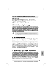
...BIN folder in the Support CD to the User Manual (PDF file) contained in the Support CD. 4. BIOS Information The Flash Memory on the motherboard stores BIOS Setup Utility. For the detailed information about BIOS Setup, please refer to display the menus. 37 ASRock P45R2000-WiFi / P45R2000 / P45TurboTwins2000 Motherboard English It will enhance motherboard features... during overclocking, but PCI / PCIE buses are in the fixed mode so that will display the Main Menu automatically if "AUTORUN" is designed to [Manual]. To begin using the Support CD, insert the CD into your computer.
...BIN folder in the Support CD to the User Manual (PDF file) contained in the Support CD. 4. BIOS Information The Flash Memory on the motherboard stores BIOS Setup Utility. For the detailed information about BIOS Setup, please refer to display the menus. 37 ASRock P45R2000-WiFi / P45R2000 / P45TurboTwins2000 Motherboard English It will enhance motherboard features... during overclocking, but PCI / PCIE buses are in the fixed mode so that will display the Main Menu automatically if "AUTORUN" is designed to [Manual]. To begin using the Support CD, insert the CD into your computer.
