
User Manual
Page 7
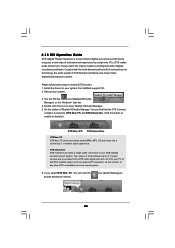
...Speaker/Rear Speaker/Central/Bass/ Line in /Front Speaker/Microphone (see CAUTION 10) - 1 x ATA133 IDE connector (supports 2 x IDE devices) - 1 x Floppy connector - 1 x DeskExpress Hot Plug Detection header - 1 x COM port header - 1 x HDMI_SPDIF header - 1 x IEEE 1394 header (P43R1600Twins-WiFi / P43R1600Twins-110dB...12V power connector 7 Supports Software Access Point mode (AP mode) and Station mode (Infrastructure mode and Ad-hoc mode) P43R1600Twins-WiFi / P43R1600Twins-110dB ASRock 1394_SPDIF I /O Connector - Wireless LAN (For P43R1600 Twins-WiFi Only) Rear Panel I /O - 1 x PS/2 ...
...Speaker/Rear Speaker/Central/Bass/ Line in /Front Speaker/Microphone (see CAUTION 10) - 1 x ATA133 IDE connector (supports 2 x IDE devices) - 1 x Floppy connector - 1 x DeskExpress Hot Plug Detection header - 1 x COM port header - 1 x HDMI_SPDIF header - 1 x IEEE 1394 header (P43R1600Twins-WiFi / P43R1600Twins-110dB...12V power connector 7 Supports Software Access Point mode (AP mode) and Station mode (Infrastructure mode and Ad-hoc mode) P43R1600Twins-WiFi / P43R1600Twins-110dB ASRock 1394_SPDIF I /O Connector - Wireless LAN (For P43R1600 Twins-WiFi Only) Rear Panel I /O - 1 x PS/2 ...

User Manual
Page 11
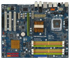
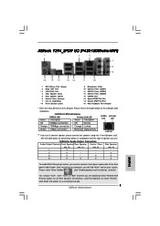
...), Orange) 16 SATAII Connector (SATAII_5 (Port4), Red) 17 System Panel Header (PANEL1) 18 USB 2.0 Header (USB4_5, Blue) 19 USB 2.0 Header (USB6_7, Blue) 20 Chassis Speaker Header (SPEAKER 1) 21 SPI BIOS Chip 22 Chassis Fan Connector (CHA_FAN1) 23 Front Panel IEEE 1394 Header (FRONT_1394) 24 Clear CMOS Jumper (CLRCMOS1) 25 Floppy Connector (FLOPPY1...
...), Orange) 16 SATAII Connector (SATAII_5 (Port4), Red) 17 System Panel Header (PANEL1) 18 USB 2.0 Header (USB4_5, Blue) 19 USB 2.0 Header (USB6_7, Blue) 20 Chassis Speaker Header (SPEAKER 1) 21 SPI BIOS Chip 22 Chassis Fan Connector (CHA_FAN1) 23 Front Panel IEEE 1394 Header (FRONT_1394) 24 Clear CMOS Jumper (CLRCMOS1) 25 Floppy Connector (FLOPPY1...

User Manual
Page 12
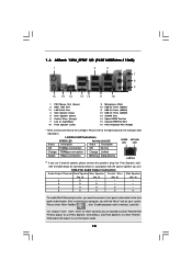
... "ok". Choose "2CH", "4CH", "6CH", or "8CH" and then you use. After restarting your computer, you use 2-channel speaker, please connect the speaker's plug into "Front Speaker Jack". TABLE for the LAN port LED indications. 1 . 5 ASRock 1394_SPDIF I/O (P43R1600Twins-WiFi) 1 2 3 4 7 5 8 6 9 16 15 14 13 12 11 10 1 PS/2 Mouse Port (Green) 2 IEEE 1394 Port * 3 LAN RJ...
... "ok". Choose "2CH", "4CH", "6CH", or "8CH" and then you use. After restarting your computer, you use 2-channel speaker, please connect the speaker's plug into "Front Speaker Jack". TABLE for the LAN port LED indications. 1 . 5 ASRock 1394_SPDIF I/O (P43R1600Twins-WiFi) 1 2 3 4 7 5 8 6 9 16 15 14 13 12 11 10 1 PS/2 Mouse Port (Green) 2 IEEE 1394 Port * 3 LAN RJ...
User Manual
Page 13
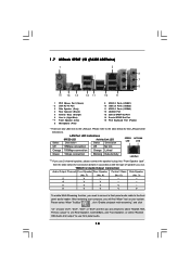
... header. See the table below for connection details in accordance with the type of speaker you are two LED next to the LAN port. Please select "Mixer ToolBox" , click "Enable playback multi-streaming", and click "ok". 1 . 6 ASRock 1394_SPDIF I/O (P43R1600Twins-110dB) 1 2 3 4 7 5 8 6 9 16 15 14 13 12 11 10 1 PS/2 Mouse Port (Green) 2 IEEE 1394 Port...
... header. See the table below for connection details in accordance with the type of speaker you are two LED next to the LAN port. Please select "Mixer ToolBox" , click "Enable playback multi-streaming", and click "ok". 1 . 6 ASRock 1394_SPDIF I/O (P43R1600Twins-110dB) 1 2 3 4 7 5 8 6 9 16 15 14 13 12 11 10 1 PS/2 Mouse Port (Green) 2 IEEE 1394 Port...
User Manual
Page 14
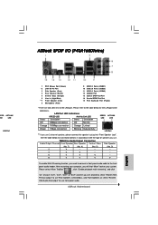
... multi-streaming", and click "ok". TABLE for the LAN port LED indications. 1 . 7 ASRock SPDIF I/O (P43R1600Twins) 1 2 3 6 4 7 5 8 15 14 13 12 11 10 9 1 PS/2 Mouse Port (Green) * 2 LAN RJ-45 Port 3 Side Speaker (Gray) 4 Rear Speaker (Black) 5 Central / Bass (Orange) 6 Line In (Light Blue) **7 Front Speaker (Lime) 8 Microphone (Pink) 9 USB 2.0 Ports (USB01) 10 USB 2.0 Ports (USB23) 11...
... multi-streaming", and click "ok". TABLE for the LAN port LED indications. 1 . 7 ASRock SPDIF I/O (P43R1600Twins) 1 2 3 6 4 7 5 8 15 14 13 12 11 10 9 1 PS/2 Mouse Port (Green) * 2 LAN RJ-45 Port 3 Side Speaker (Gray) 4 Rear Speaker (Black) 5 Central / Bass (Orange) 6 Line In (Light Blue) **7 Front Speaker (Lime) 8 Microphone (Pink) 9 USB 2.0 Ports (USB01) 10 USB 2.0 Ports (USB23) 11...
User Manual
Page 28
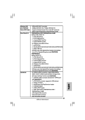
...this motherboard provides 24-pin ATX power connector, 13 1 it to Pin 1-3. System Panel Header (9-pin PANEL1) (see p.11 No. 17) Chassis Speaker Header (4-pin SPEAKER 1) (see p.11 No. 20) Chassis Fan Connector (3-pin CHA_FAN1) (see p.11 No. 22) PLED+ PLEDPWRBTN# GND 1 DUMMY RESET# GND... HDLEDHDLED+ This header accommodates several system front panel functions. 1 SPEAKER DUMMY DUMMY +5V Please connect the chassis speaker to this connector and match the black wire to the ground pin. CPU Fan Connector (4-pin CPU_FAN1) (see p.11 No. 2)...
...this motherboard provides 24-pin ATX power connector, 13 1 it to Pin 1-3. System Panel Header (9-pin PANEL1) (see p.11 No. 17) Chassis Speaker Header (4-pin SPEAKER 1) (see p.11 No. 20) Chassis Fan Connector (3-pin CHA_FAN1) (see p.11 No. 22) PLED+ PLEDPWRBTN# GND 1 DUMMY RESET# GND... HDLEDHDLED+ This header accommodates several system front panel functions. 1 SPEAKER DUMMY DUMMY +5V Please connect the chassis speaker to this connector and match the black wire to the ground pin. CPU Fan Connector (4-pin CPU_FAN1) (see p.11 No. 2)...
User Manual
Page 45
... DTS Interactive provides a single cable connection to any DTS enabled system such as, powered PC speakers, an A/V receiver or any other digitally encoded soundtracks. DTS makes audio tracks more ) into a DTS audio signal and sent out from ASRock support CD. 2. You can click the access advanced controls. Your stereo or multi-channel...
... DTS Interactive provides a single cable connection to any DTS enabled system such as, powered PC speakers, an A/V receiver or any other digitally encoded soundtracks. DTS makes audio tracks more ) into a DTS audio signal and sent out from ASRock support CD. 2. You can click the access advanced controls. Your stereo or multi-channel...

Quick Installation Guide
Page 2
... ATX Power Connector (ATXPWR1) 18 USB 2.0 Header (USB4_5, Blue) 39 eSATAII Connector (eSATAII_TOP) 19 USB 2.0 Header (USB6_7, Blue) 40 ATX 12V Connector (ATX12V1) 20 Chassis Speaker Header (SPEAKER 1) 2 ASRock Motherboard
... ATX Power Connector (ATXPWR1) 18 USB 2.0 Header (USB4_5, Blue) 39 eSATAII Connector (eSATAII_TOP) 19 USB 2.0 Header (USB6_7, Blue) 40 ATX 12V Connector (ATX12V1) 20 Chassis Speaker Header (SPEAKER 1) 2 ASRock Motherboard
Quick Installation Guide
Page 3
... below for Audio Output Connection Audio Output Channels Front Speaker Rear Speaker Central / Bass Side Speaker (No. 8) (No. 5) (No. 6) (No. 4) 2 V -- -- -- 4 V -- -- ASRock 1394_SPDIF I/O (P43R1600Twins-WiFi) 1 PS/2 Mouse Port (Green) 2 IEEE 1394 Port * 3 LAN RJ-45 Port 4 Side Speaker (Gray) 5 Rear Speaker (Black) 6 Central / Bass (Orange) 7 Line In (Light Blue) **8 Front Speaker (Lime) 9 Microphone (Pink) 10 USB 2.0 Ports (USB01) 11...
... below for Audio Output Connection Audio Output Channels Front Speaker Rear Speaker Central / Bass Side Speaker (No. 8) (No. 5) (No. 6) (No. 4) 2 V -- -- -- 4 V -- -- ASRock 1394_SPDIF I/O (P43R1600Twins-WiFi) 1 PS/2 Mouse Port (Green) 2 IEEE 1394 Port * 3 LAN RJ-45 Port 4 Side Speaker (Gray) 5 Rear Speaker (Black) 6 Central / Bass (Orange) 7 Line In (Light Blue) **8 Front Speaker (Lime) 9 Microphone (Pink) 10 USB 2.0 Ports (USB01) 11...

Quick Installation Guide
Page 4
...to the table below for connection details in accordance with the type of speaker you will find "Mixer" tool on your computer, you use front panel audio. 4 ASRock Motherboard English TABLE for the LAN port LED indications. Status LAN Port ... playback multi-streaming", and click "ok". After restarting your system. ASRock 1394_SPDIF I/O (P43R1600Twins-110dB) 1 PS/2 Mouse Port (Green) 2 IEEE 1394 Port * 3 LAN RJ-45 Port 4 Side Speaker (Gray) 5 Rear Speaker (Black) 6 Central / Bass (Orange) 7 Line In (Light Blue) **8 Front Speaker (Lime) 9 Microphone (Pink) 10 USB 2.0 Ports (USB01) ...
...to the table below for connection details in accordance with the type of speaker you will find "Mixer" tool on your computer, you use front panel audio. 4 ASRock Motherboard English TABLE for the LAN port LED indications. Status LAN Port ... playback multi-streaming", and click "ok". After restarting your system. ASRock 1394_SPDIF I/O (P43R1600Twins-110dB) 1 PS/2 Mouse Port (Green) 2 IEEE 1394 Port * 3 LAN RJ-45 Port 4 Side Speaker (Gray) 5 Rear Speaker (Black) 6 Central / Bass (Orange) 7 Line In (Light Blue) **8 Front Speaker (Lime) 9 Microphone (Pink) 10 USB 2.0 Ports (USB01) ...
Quick Installation Guide
Page 5
... the table below for Audio Output Connection Audio Output Channels Front Speaker Rear Speaker Central / Bass Side Speaker (No. 7) (No. 4) (No. 5) (No. 3) 2 V -- -- -- 4 V V -- -- 6 V V V -- 8 V V V V To enable Multi-Streaming function, you are two LED next to use 2-channel speaker, please connect the speaker's plug into "Front Speaker Jack". ASRock SPDIF I/O (P43R1600Twins) PEED ACT/LINK LED LED LAN Port 1 PS/2 Mouse Port...
... the table below for Audio Output Connection Audio Output Channels Front Speaker Rear Speaker Central / Bass Side Speaker (No. 7) (No. 4) (No. 5) (No. 3) 2 V -- -- -- 4 V V -- -- 6 V V V -- 8 V V V V To enable Multi-Streaming function, you are two LED next to use 2-channel speaker, please connect the speaker's plug into "Front Speaker Jack". ASRock SPDIF I/O (P43R1600Twins) PEED ACT/LINK LED LED LAN Port 1 PS/2 Mouse Port...
Quick Installation Guide
Page 9
... (supports 2 x IDE devices) - 1 x Floppy connector - 1 x DeskExpress Hot Plug Detection header - 1 x COM port header - 1 x HDMI_SPDIF header - 1 x IEEE 1394 header (P43R1600Twins-WiFi / P43R1600Twins-110dB) - HD Audio Jack: Side Speaker/Rear Speaker/Central/Bass/ Line in /Front Speaker/Microphone (see CAUTION 8) P43R1600Twins ASRock SPDIF I/O - 1 x PS/2 Mouse Port - 1 x PS/2 Keyboard Port - 1 x Coaxial SPDIF Out Port - 1 x Optical SPDIF Out Port - 6 x Ready-to -Use...
... (supports 2 x IDE devices) - 1 x Floppy connector - 1 x DeskExpress Hot Plug Detection header - 1 x COM port header - 1 x HDMI_SPDIF header - 1 x IEEE 1394 header (P43R1600Twins-WiFi / P43R1600Twins-110dB) - HD Audio Jack: Side Speaker/Rear Speaker/Central/Bass/ Line in /Front Speaker/Microphone (see CAUTION 8) P43R1600Twins ASRock SPDIF I/O - 1 x PS/2 Mouse Port - 1 x PS/2 Keyboard Port - 1 x Coaxial SPDIF Out Port - 1 x Optical SPDIF Out Port - 6 x Ready-to -Use...

Quick Installation Guide
Page 24
... power supply, please plug your power supply along with Pin 1 and Pin 13. 20-Pin ATX Power Supply Installation 24 12 English 24 ASRock Motherboard Pin 1-3 Connected 3-Pin Fan Installation ATX Power Connector (24-pin ATXPWR1) (see p.2, No. 38) 13 1 Please connect an ...ATX power supply to the ground pin. System Panel Header (9-pin PANEL1) (see p.2 No. 2) Please connect the chassis speaker to this header. Chassis Speaker Header (4-pin SPEAKER 1) (see p.2 No. 20) Chassis Fan Connector (3-pin CHA_FAN1) (see p.2 No. 22) CPU Fan Connector (4-pin CPU_FAN1) (see p.2 ...
... power supply, please plug your power supply along with Pin 1 and Pin 13. 20-Pin ATX Power Supply Installation 24 12 English 24 ASRock Motherboard Pin 1-3 Connected 3-Pin Fan Installation ATX Power Connector (24-pin ATXPWR1) (see p.2, No. 38) 13 1 Please connect an ...ATX power supply to the ground pin. System Panel Header (9-pin PANEL1) (see p.2 No. 2) Please connect the chassis speaker to this header. Chassis Speaker Header (4-pin SPEAKER 1) (see p.2 No. 20) Chassis Fan Connector (3-pin CHA_FAN1) (see p.2 No. 22) CPU Fan Connector (4-pin CPU_FAN1) (see p.2 ...

Quick Installation Guide
Page 31
...Reboot your system. 3. Click the button to your DTS enabled surround sound system. Your stereo or multi-channel (up to English 31 ASRock Motherboard If you a new class of entertainment experience by using home PCs. DTS Interactive DTS Interactive provides a single cable connection to enable ...) is a multi-channel digital surround sound format to your system from your PC to any DTS enabled system such as, powered PC speakers, an A/V receiver or any other digitally encoded soundtracks. You can click the access advanced controls. Install the drivers to bring you select...
...Reboot your system. 3. Click the button to your DTS enabled surround sound system. Your stereo or multi-channel (up to English 31 ASRock Motherboard If you a new class of entertainment experience by using home PCs. DTS Interactive DTS Interactive provides a single cable connection to enable ...) is a multi-channel digital surround sound format to your system from your PC to any DTS enabled system such as, powered PC speakers, an A/V receiver or any other digitally encoded soundtracks. You can click the access advanced controls. Install the drivers to bring you select...
