
User Manual
Page 3
... 13 2.3 CPU Installation 14 2.4 Installation of Heatsink and CPU fan 16 2.5 Installation of Memory Modules (DIMM 17 2.6 Expansion Slots (PCI and PCI Express Slots 19 2.7 Jumpers Setup 20 2.8 Onboard Headers and Connectors 21 2.9 HDMI_SPDIF Header Connection Guide 26 2.10 SATAII Hard Disk Setup Guide 27 2.11 Serial ATA (SATA) / Serial ATAII (SATAII) Hard Disks Installation 28 2.12 Hot Plug Function for SATA / SATAII HDDs 28 2.13 SATA / SATAII HDD Hot Plug Feature and Operation Guide 29 2.14 Driver Installation Guide 31 2.15 Installing Windows® 2000 / XP / XP 64-bit / VistaTM...
... 13 2.3 CPU Installation 14 2.4 Installation of Heatsink and CPU fan 16 2.5 Installation of Memory Modules (DIMM 17 2.6 Expansion Slots (PCI and PCI Express Slots 19 2.7 Jumpers Setup 20 2.8 Onboard Headers and Connectors 21 2.9 HDMI_SPDIF Header Connection Guide 26 2.10 SATAII Hard Disk Setup Guide 27 2.11 Serial ATA (SATA) / Serial ATAII (SATAII) Hard Disks Installation 28 2.12 Hot Plug Function for SATA / SATAII HDDs 28 2.13 SATA / SATAII HDD Hot Plug Feature and Operation Guide 29 2.14 Driver Installation Guide 31 2.15 Installing Windows® 2000 / XP / XP 64-bit / VistaTM...

User Manual
Page 8
... motherboard supports 2-channel, 4- channel, 6-channel, and 8-channel modes. Please check the table on page 33 for possible damage caused by overclocking. CAUTION! 1. Before installing SATAII hard disk to SATAII connector, please read the installation guide of memory modules on page 27 to adjust your own risk and expense. It should be used to SATAII connector directly. 8. This motherboard supports Dual Channel Memory Technology. For Windows® XP 64-bit and Windows® VistaTM 64-bit with 64-bit CPU...
... motherboard supports 2-channel, 4- channel, 6-channel, and 8-channel modes. Please check the table on page 33 for possible damage caused by overclocking. CAUTION! 1. Before installing SATAII hard disk to SATAII connector, please read the installation guide of memory modules on page 27 to adjust your own risk and expense. It should be used to SATAII connector directly. 8. This motherboard supports Dual Channel Memory Technology. For Windows® XP 64-bit and Windows® VistaTM 64-bit with 64-bit CPU...

User Manual
Page 10
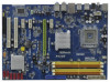
... USB 2.0 Header (USB8_9, Blue) 20 Chassis Speaker Header (SPEAKER 1, Purple) 21 System Panel Header (PANEL1, Orange) 22 SPI BIOS Chip 23 Clear CMOS Jumper (CLRCMOS1) 24 COM Port Header (COM1) 25 Floppy Connector (FLOPPY1) 26 Infrared Module Header (IR1) 27 HDMI_SPDIF Header (HDMI_SPDIF1, Yellow) 28 PCI Slots (PCI1 - 2) 29 USB/WiFi Header (USB/WIFI, Yellow) 30 PCI Express x1 Slot (PCIE4) 31 PCI Express x1 Slot (PCIE3) 32 Front Panel Audio Header (HD_AUDIO1, Lime) 33 PCI Express 2.0 x16 Slot (PCIE2, Green) 34 Internal Audio Connector: CD1 (Black) 35 PCI Express x1 Slot...
... USB 2.0 Header (USB8_9, Blue) 20 Chassis Speaker Header (SPEAKER 1, Purple) 21 System Panel Header (PANEL1, Orange) 22 SPI BIOS Chip 23 Clear CMOS Jumper (CLRCMOS1) 24 COM Port Header (COM1) 25 Floppy Connector (FLOPPY1) 26 Infrared Module Header (IR1) 27 HDMI_SPDIF Header (HDMI_SPDIF1, Yellow) 28 PCI Slots (PCI1 - 2) 29 USB/WiFi Header (USB/WIFI, Yellow) 30 PCI Express x1 Slot (PCIE4) 31 PCI Express x1 Slot (PCIE3) 32 Front Panel Audio Header (HD_AUDIO1, Lime) 33 PCI Express 2.0 x16 Slot (PCIE2, Green) 34 Internal Audio Connector: CD1 (Black) 35 PCI Express x1 Slot...

User Manual
Page 22
... receive stereo audio input from sound sources such as a CD-ROM, DVD-ROM, TV tuner card, or MPEG card. 22 This header supports an optional wireless transmitting and receiving infrared module. It can also be used to support WiFi+AP function with ASRock WiFi-802. 11g or WiFi-802.11n module, an easy-to the power connector of the power supply. Serial ATA (SATA) Power Cable (Optional) connect to the SATA HDD power connector connect to the power supply USB 2.0 Headers (9-pin USB8_9...
... receive stereo audio input from sound sources such as a CD-ROM, DVD-ROM, TV tuner card, or MPEG card. 22 This header supports an optional wireless transmitting and receiving infrared module. It can also be used to support WiFi+AP function with ASRock WiFi-802. 11g or WiFi-802.11n module, an easy-to the power connector of the power supply. Serial ATA (SATA) Power Cable (Optional) connect to the SATA HDD power connector connect to the power supply USB 2.0 Headers (9-pin USB8_9...

User Manual
Page 26
...motherboard. To use HDMI function on HDMI_SPDIF cable. Step 1. For the pin definition of HDMI VGA card. (There are two white ends (2-pin and 3-pin) on this motherboard and the HDMI VGA card. Install HDMI VGA card driver to the user manual of PCI Express VGA card. A complete HDMI system requires a HDMI VGA card and a HDMI ready motherboard with a HDMI_SPDIF header, which provides an interface between any compatible digital audio/ video source, such as a set-top box, DVD player, A/V receiver and a compatible digital audio or video monitor, such as HDTV. Install the HDMI VGA card...
...motherboard. To use HDMI function on HDMI_SPDIF cable. Step 1. For the pin definition of HDMI VGA card. (There are two white ends (2-pin and 3-pin) on this motherboard and the HDMI VGA card. Install HDMI VGA card driver to the user manual of PCI Express VGA card. A complete HDMI system requires a HDMI VGA card and a HDMI ready motherboard with a HDMI_SPDIF header, which provides an interface between any compatible digital audio/ video source, such as a set-top box, DVD player, A/V receiver and a compatible digital audio or video monitor, such as HDTV. Install the HDMI VGA card...
User Manual
Page 31
... / XP 64-bit OS on the support CD driver page. A. Therefore, the drivers you install can be auto-detected and listed on your SATA / SATAII HDDs without RAID functions, please follow the order from up , press key, and then a window for boot devices selection appears. A. Using SATA / SATAII HDDs with NCQ function STEP 1: Set Up BIOS. The system will lose ALL data in the option "Configure SATAII as the boot device. When you...
... / XP 64-bit OS on the support CD driver page. A. Therefore, the drivers you install can be auto-detected and listed on your SATA / SATAII HDDs without RAID functions, please follow the order from up , press key, and then a window for boot devices selection appears. A. Using SATA / SATAII HDDs with NCQ function STEP 1: Set Up BIOS. The system will lose ALL data in the option "Configure SATAII as the boot device. When you...
User Manual
Page 38
... CPU frequency and PCIE frequency in the following two items. If you install Windows® VistaTM and want to enable this function, please set this motherboard. The configuration options depend on the CPU and memory module you select [Manual], Untied Overclocking function is enabled. Intel (R) SpeedStep(tm) tech. The default value is selected, the motherboard will be hidden if the current CPU does not support Intel (R) SpeedStep(tm) tech.. Configuration options: [Auto], [Enabled] and [Disabled...
... CPU frequency and PCIE frequency in the following two items. If you install Windows® VistaTM and want to enable this function, please set this motherboard. The configuration options depend on the CPU and memory module you select [Manual], Untied Overclocking function is enabled. Intel (R) SpeedStep(tm) tech. The default value is selected, the motherboard will be hidden if the current CPU does not support Intel (R) SpeedStep(tm) tech.. Configuration options: [Auto], [Enabled] and [Disabled...

User Manual
Page 40
... native processor instructions HLT and MWAIT and requires no hardware support from the chipset. In the C1 power state, the processor maintains the context of Boot Failure Guard. Overclock Mode Use this motherboard. Spread Spectrum This item should always be [Auto] for the details of this motherboard. Ratio CMOS Setting If the ratio status is heavy loaded. PCIE Frequency (MHz) Use this option to adjust PCIE frequency. CPU Frequency (MHz) Use this option to adjust CPU frequency. Boot Failure Guard Enable or disable...
... native processor instructions HLT and MWAIT and requires no hardware support from the chipset. In the C1 power state, the processor maintains the context of Boot Failure Guard. Overclock Mode Use this motherboard. Spread Spectrum This item should always be [Auto] for the details of this motherboard. Ratio CMOS Setting If the ratio status is heavy loaded. PCIE Frequency (MHz) Use this option to adjust PCIE frequency. CPU Frequency (MHz) Use this option to adjust CPU frequency. Boot Failure Guard Enable or disable...

User Manual
Page 41
... [Auto], you install Windows® VistaTM and want to enable this function, please set this function may select [Enabled] to enable P4 CPU internal thermal control mechanism to keep the CPU from being used by malicious software to [Enabled] if using Microsoft® Windows® XP, VistaTM, or Linux kernel version 2.4.18 or higher. Intel (R) Virtualization tech. An IA-32 processor with an Intel Pentium® 4 processor that supports Hyper-Threading technology...
... [Auto], you install Windows® VistaTM and want to enable this function, please set this function may select [Enabled] to enable P4 CPU internal thermal control mechanism to keep the CPU from being used by malicious software to [Enabled] if using Microsoft® Windows® XP, VistaTM, or Linux kernel version 2.4.18 or higher. Intel (R) Virtualization tech. An IA-32 processor with an Intel Pentium® 4 processor that supports Hyper-Threading technology...

User Manual
Page 42
..., software can manage each core independently, while the actual power management adheres to [Enabled]. Configuration options are: [C2], [C3], [C4] and [Disabled]. The default value is [Disabled]. The default value is [Disabled]. 3.4.3Chipset Configuration BIOS SETUP UTILITY Advanced Chipset Settings Memory Remap Feature [Disabled] DRAM Frequency [Auto] Flexibility Option [Disabled] Standard Memory Info : 5-6-6-18-42-6-3-3-3 DRAM tCL [Auto] DRAM tRCD [Auto] DRAM tRP [Auto] DRAM tRAS [Auto] DRAM tRFC [Auto] DRAM tWR [Auto] DRAM tWTR [Auto] DRAM tRRD [Auto] DRAM tRTP...
..., software can manage each core independently, while the actual power management adheres to [Enabled]. Configuration options are: [C2], [C3], [C4] and [Disabled]. The default value is [Disabled]. The default value is [Disabled]. 3.4.3Chipset Configuration BIOS SETUP UTILITY Advanced Chipset Settings Memory Remap Feature [Disabled] DRAM Frequency [Auto] Flexibility Option [Disabled] Standard Memory Info : 5-6-6-18-42-6-3-3-3 DRAM tCL [Auto] DRAM tRCD [Auto] DRAM tRP [Auto] DRAM tRAS [Auto] DRAM tRFC [Auto] DRAM tWR [Auto] DRAM tWTR [Auto] DRAM tRRD [Auto] DRAM tRTP...

User Manual
Page 44
... [PCI] or [PCI Express] as the boot graphic adapter priority. CD-In Use this item to submit Windows® VistaTM logo test, please disable this option. please set this item to enable or disable CIR10 Field 1. OnBoard Lan This allows you plan to use this motherboard to enable or disable CD-In of this feature is [Enabled]. 44 Besides the BIOS option, you select [Auto], the onboard HD Audio will be disabled when PCI Sound Card is [PCI]. The default...
... [PCI] or [PCI Express] as the boot graphic adapter priority. CD-In Use this item to submit Windows® VistaTM logo test, please disable this option. please set this item to enable or disable CIR10 Field 1. OnBoard Lan This allows you plan to use this motherboard to enable or disable CD-In of this feature is [Enabled]. 44 Besides the BIOS option, you select [Auto], the onboard HD Audio will be disabled when PCI Sound Card is [PCI]. The default...

User Manual
Page 46
... set the IDE configuration for the device that will improve SATA disk performance but IDE mode does not have these advantages. Then in the following instruction. 46 ACPI HPET Table Use this item to [IDE] or [AHCI]. The default value is enabled. The default value is [Disabled]. The default value is [Enabled]. Configuration options: [Enabled] and [Disabled]. OnBoard IDE Controller Use this item to [Enabled] if you select [AHCI] mode, the option "Hot Plug" will use the Hot Plug function under Windows environment if this option...
... set the IDE configuration for the device that will improve SATA disk performance but IDE mode does not have these advantages. Then in the following instruction. 46 ACPI HPET Table Use this item to [IDE] or [AHCI]. The default value is enabled. The default value is [Disabled]. The default value is [Enabled]. Configuration options: [Enabled] and [Disabled]. OnBoard IDE Controller Use this item to [Enabled] if you select [AHCI] mode, the option "Hot Plug" will use the Hot Plug function under Windows environment if this option...

User Manual
Page 50
... are allowed to use only under legacy OS and BIOS setup when [Disabled] is recommended to select [Disabled] to select legacy support for USB devices. USB devices are four configuration options: [Enabled], [Auto], [Disabled] and [BIOS Setup Only]. The default value is [BIOS Setup Only]. 3.4.9USB Configuration BIOS SETUP UTILITY Advanced USB Configuration USB Controller USB 2.0 Support Legacy USB Support [Enabled] [Enabled] [BIOS Setup Only] To enable or disable the onboard USB controllers. +F1 F9 F10 ESC Select Screen Select Item Change Option General Help Load Defaults Save and...
... are allowed to use only under legacy OS and BIOS setup when [Disabled] is recommended to select [Disabled] to select legacy support for USB devices. USB devices are four configuration options: [Enabled], [Auto], [Disabled] and [BIOS Setup Only]. The default value is [BIOS Setup Only]. 3.4.9USB Configuration BIOS SETUP UTILITY Advanced USB Configuration USB Controller USB 2.0 Support Legacy USB Support [Enabled] [Enabled] [BIOS Setup Only] To enable or disable the onboard USB controllers. +F1 F9 F10 ESC Select Screen Select Item Change Option General Help Load Defaults Save and...
User Manual
Page 53
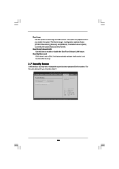
... Screen Select Item Enter Change F1 General Help F9 Load Defaults F10 Save and Exit ESC Exit v02.54 (C) Copyright 1985-2005, American Megatrends, Inc. 53 Boot Logo Use this option to enable or disable the Boot From Onboard LAN feature. The default value is set to Aircraft. Boot Up Num-Lock If this item is set to [On], it . BIOS SETUP UTILITY Main Smart Advanced H/W Monitor Boot Security Exit Security Settings Supervisor Password : Not Installed User Password : Not Installed Change...
... Screen Select Item Enter Change F1 General Help F9 Load Defaults F10 Save and Exit ESC Exit v02.54 (C) Copyright 1985-2005, American Megatrends, Inc. 53 Boot Logo Use this option to enable or disable the Boot From Onboard LAN feature. The default value is set to Aircraft. Boot Up Num-Lock If this item is set to [On], it . BIOS SETUP UTILITY Main Smart Advanced H/W Monitor Boot Security Exit Security Settings Supervisor Password : Not Installed User Password : Not Installed Change...
User Manual
Page 55
.... Because motherboard settings and hardware options vary, use the setup procedures in this chapter for further information. 55 Please install the necessary drivers to display the menus. 4.2.2 Drivers Menu The Drivers Menu shows the available devices drivers if the system detects installed devices. Click on the file "ASSETUP.EXE" from the BIN folder in your CD-ROM drive. The CD automatically displays the Main Menu if "AUTORUN" is enabled in the Support CD to...
.... Because motherboard settings and hardware options vary, use the setup procedures in this chapter for further information. 55 Please install the necessary drivers to display the menus. 4.2.2 Drivers Menu The Drivers Menu shows the available devices drivers if the system detects installed devices. Click on the file "ASSETUP.EXE" from the BIN folder in your CD-ROM drive. The CD automatically displays the Main Menu if "AUTORUN" is enabled in the Support CD to...
Quick Installation Guide
Page 7
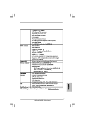
...P43DE Motherboard AMI Legal BIOS - ASRock U-COP (see CAUTION 9) BIOS Feature - 8Mb AMI BIOS - AMBIOS 2.3.1 Support - CPU Quiet Fan - CPU Temperature Sensing Monitor - Front panel audio connector - 2 x USB 2.0 headers (support 4 USB 2.0 ports) (see CAUTION 8) - 1 x USB/WiFi header (see CAUTION 13) - Hybrid Booster: - Chassis Fan Tachometer - Drivers, Utilities, AntiVirus Software (Trial Version) Unique Feature - Boot Failure Guard (B.F.G.) Hardware - CPU/Chassis FAN connector - 24 pin ATX power connector - 8 pin 12V power connector - O. ACPI...
...P43DE Motherboard AMI Legal BIOS - ASRock U-COP (see CAUTION 9) BIOS Feature - 8Mb AMI BIOS - AMBIOS 2.3.1 Support - CPU Quiet Fan - CPU Temperature Sensing Monitor - Front panel audio connector - 2 x USB 2.0 headers (support 4 USB 2.0 ports) (see CAUTION 8) - 1 x USB/WiFi header (see CAUTION 13) - Hybrid Booster: - Chassis Fan Tachometer - Drivers, Utilities, AntiVirus Software (Trial Version) Unique Feature - Boot Failure Guard (B.F.G.) Hardware - CPU/Chassis FAN connector - 24 pin ATX power connector - 8 pin 12V power connector - O. ACPI...
Quick Installation Guide
Page 8
...hard disk to support 2 USB 2.0 ports. For microphone input, this motherboard supports 2-channel, 4- You can be used to SATAII connector, please read "Untied Overclocking Technology" on page 23 for proper installation. 4. ASRock website http://www.asrock.com English 8 ASRock P43DE Motherboard We are not responsible for the CPU FSB frequency and its corresponding memory support frequency. channel, 6-channel, and 8-channel modes. Power Management for proper connection. 7. USB/WiFi header can also connect SATA hard disk to SATAII mode. CPU FSB Frequency Memory...
...hard disk to support 2 USB 2.0 ports. For microphone input, this motherboard supports 2-channel, 4- You can be used to SATAII connector, please read "Untied Overclocking Technology" on page 23 for proper installation. 4. ASRock website http://www.asrock.com English 8 ASRock P43DE Motherboard We are not responsible for the CPU FSB frequency and its corresponding memory support frequency. channel, 6-channel, and 8-channel modes. Power Management for proper connection. 7. USB/WiFi header can also connect SATA hard disk to SATAII mode. CPU FSB Frequency Memory...

Quick Installation Guide
Page 18
..., an easy-to receive stereo audio input from sound sources such as a CD-ROM, DVD-ROM, TV tuner card, or MPEG card. 18 ASRock P43DE Motherboard English It can support two USB 2.0 ports. This header supports an optional wireless transmitting and receiving infrared module. This connector allows you to support 2 USB 2.0 ports. Besides six default USB 2.0 ports on the I/O panel, there are two USB 2.0 headers on each drive. Serial ATA (SATA) Power Cable (Optional) connect to the SATA HDD power connector connect to the power supply USB 2.0 Headers (9-pin USB8_9) (see p.2 No. 19...
..., an easy-to receive stereo audio input from sound sources such as a CD-ROM, DVD-ROM, TV tuner card, or MPEG card. 18 ASRock P43DE Motherboard English It can support two USB 2.0 ports. This header supports an optional wireless transmitting and receiving infrared module. This connector allows you to support 2 USB 2.0 ports. Besides six default USB 2.0 ports on the I/O panel, there are two USB 2.0 headers on each drive. Serial ATA (SATA) Power Cable (Optional) connect to the SATA HDD power connector connect to the power supply USB 2.0 Headers (9-pin USB8_9) (see p.2 No. 19...

Quick Installation Guide
Page 19
... panel functions. English 19 ASRock P43DE Motherboard Connect Mic_IN (MIC) to this connector and match the black wire to Ground (GND). B. Chassis Speaker Header (4-pin SPEAKER 1) (see p.2 No. 20) Chassis Fan Connector (3-pin CHA_FAN1) (see p.2 No. 15) CPU Fan Connector 1 (4-pin CPU_FAN1) 2 3 (see p.2, No. 4) 4 Please connect the chassis speaker to MIC2_L. Please connect a CPU fan cable to this header. Connect Ground (GND) to the ground pin. Enter Advanced Settings, and then select Chipset Configuration. Connect Audio_R (RIN) to OUT2_R and Audio_L (LIN) to install...
... panel functions. English 19 ASRock P43DE Motherboard Connect Mic_IN (MIC) to this connector and match the black wire to Ground (GND). B. Chassis Speaker Header (4-pin SPEAKER 1) (see p.2 No. 20) Chassis Fan Connector (3-pin CHA_FAN1) (see p.2 No. 15) CPU Fan Connector 1 (4-pin CPU_FAN1) 2 3 (see p.2, No. 4) 4 Please connect the chassis speaker to MIC2_L. Please connect a CPU fan cable to this header. Connect Ground (GND) to the ground pin. Enter Advanced Settings, and then select Chipset Configuration. Connect Audio_R (RIN) to OUT2_R and Audio_L (LIN) to install...
Quick Installation Guide
Page 24
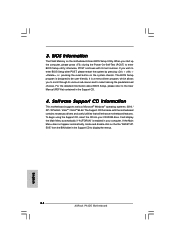
... information about BIOS Setup, please refer to the User Manual (PDF file) contained in the Support CD to be user-friendly. If the Main Menu does not appear automatically, locate and double-click on the motherboard stores BIOS Setup Utility. otherwise, POST continues with the motherboard contains necessary drivers and useful utilities that will display the Main Menu automatically if "AUTORUN" is designed to display the menus. 24 ASRock P43DE Motherboard English Software Support CD information This motherboard supports various Microsoft...
... information about BIOS Setup, please refer to the User Manual (PDF file) contained in the Support CD to be user-friendly. If the Main Menu does not appear automatically, locate and double-click on the motherboard stores BIOS Setup Utility. otherwise, POST continues with the motherboard contains necessary drivers and useful utilities that will display the Main Menu automatically if "AUTORUN" is designed to display the menus. 24 ASRock P43DE Motherboard English Software Support CD information This motherboard supports various Microsoft...


