User Manual
Page 3
... 1.6 ASRock 1394_SPDIF I/O (P43D1600Twins-1394 13 1.7 ASRock SPDIF I/O (P43D1600Twins 14 1.8 ASRock SPDIF I/O (P43Twins1600 15 2 Installation 16 2.1 Screw Holes 16 2.2 Pre-installation Precautions 16 2.3 CPU Installation 17 2.4 Installation of Heatsink and CPU fan 19 2.5 Installation of Memory Modules (DIMM 20 2.6 Expansion Slots (PCI and PCI Express Slots 22 2.7 Jumpers Setup 23 2.8 Onboard Headers and Connectors 24 2.9 HDMI_SPDIF Header Connection...
... 1.6 ASRock 1394_SPDIF I/O (P43D1600Twins-1394 13 1.7 ASRock SPDIF I/O (P43D1600Twins 14 1.8 ASRock SPDIF I/O (P43Twins1600 15 2 Installation 16 2.1 Screw Holes 16 2.2 Pre-installation Precautions 16 2.3 CPU Installation 17 2.4 Installation of Heatsink and CPU fan 19 2.5 Installation of Memory Modules (DIMM 20 2.6 Expansion Slots (PCI and PCI Express Slots 22 2.7 Jumpers Setup 23 2.8 Onboard Headers and Connectors 24 2.9 HDMI_SPDIF Header Connection...
User Manual
Page 9
...Technology", please check page 45. 3. Please visit our website for proper jumper settings. 2. This motherboard supports Untied Overclocking Technology. You can also connect SATA hard disk to -use wireless local area network (WLAN) adapter. For special overclocking mode, please refer to create a wireless environment and enjoy...to adjust your SATAII hard disk drive to SATAII connector, please read "Untied Overclocking Technology" on page 20 for proper connection. 8. ASRock website http://www.asrock.com 9 Before installing SATAII hard disk to SATAII mode.
...Technology", please check page 45. 3. Please visit our website for proper jumper settings. 2. This motherboard supports Untied Overclocking Technology. You can also connect SATA hard disk to -use wireless local area network (WLAN) adapter. For special overclocking mode, please refer to create a wireless environment and enjoy...to adjust your SATAII hard disk drive to SATAII connector, please read "Untied Overclocking Technology" on page 20 for proper connection. 8. ASRock website http://www.asrock.com 9 Before installing SATAII hard disk to SATAII mode.
User Manual
Page 13
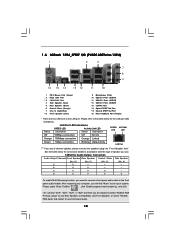
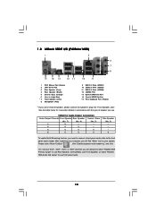
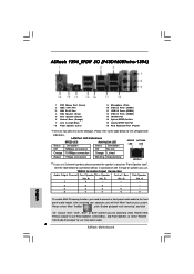
... LED indications. TABLE for Audio Output Connection Audio Output Channels Front Speaker Rear Speaker Central / Bass Side Speaker (No. 8) (No. 5) (No. 6) (No. 4) 2 V -- -- -- 4 V V -- -- 6 V V V -- 8 V V V V To enable Multi-Streaming function, you are two LED next to the front panel audio header. After restarting your computer, you use. 1 . 6 ASRock 1394_SPDIF I/O (P43D1600Twins-1394) 1 2 3 4 7 5 8 6 9 16 15 14 13 12 11...
... LED indications. TABLE for Audio Output Connection Audio Output Channels Front Speaker Rear Speaker Central / Bass Side Speaker (No. 8) (No. 5) (No. 6) (No. 4) 2 V -- -- -- 4 V V -- -- 6 V V V -- 8 V V V V To enable Multi-Streaming function, you are two LED next to the front panel audio header. After restarting your computer, you use. 1 . 6 ASRock 1394_SPDIF I/O (P43D1600Twins-1394) 1 2 3 4 7 5 8 6 9 16 15 14 13 12 11...

User Manual
Page 14
1 . 7 ASRock SPDIF I/O (P43D1600Twins) 1 2 3 6 4 7 5 8 15 14 13 12 11 10 9 1 PS/2 Mouse Port (Green) * 2 LAN RJ-45 Port 3 Side Speaker (Gray) 4 Rear Speaker (Black) 5 Central / Bass (Orange) 6 Line In (... "Realtek HDA Primary output" to use Rear Speaker, Central/Bass, and Front Speaker, or select "Realtek HDA Audio 2nd output" to the table below for connection details in accordance with the type of speaker you use front panel audio. 14 Choose "2CH", "4CH", "6CH", or "8CH" and then you are two...
1 . 7 ASRock SPDIF I/O (P43D1600Twins) 1 2 3 6 4 7 5 8 15 14 13 12 11 10 9 1 PS/2 Mouse Port (Green) * 2 LAN RJ-45 Port 3 Side Speaker (Gray) 4 Rear Speaker (Black) 5 Central / Bass (Orange) 6 Line In (... "Realtek HDA Primary output" to use Rear Speaker, Central/Bass, and Front Speaker, or select "Realtek HDA Audio 2nd output" to the table below for connection details in accordance with the type of speaker you use front panel audio. 14 Choose "2CH", "4CH", "6CH", or "8CH" and then you are two...
User Manual
Page 15
...audio. 15 Please select "Mixer ToolBox" , click "Enable playback multi-streaming", and click "ok". TABLE for connection details in accordance with the type of speaker you need to connect a front panel audio cable to use . Choose "2CH", "4CH", "6CH", or "8CH" and then ... find "Mixer" tool on your computer, you are allowed to select "Realtek HDA Primary output" to use 2-channel speaker, please connect the speaker's plug into "Front Speaker Jack". After restarting your system. 1 . 8 ASRock SPDIF I/O (P43Twins1600) 1 2 3 6 4 7 5 8 15 14 13 12 11 10 9 1 PS/2 Mouse Port (...
...audio. 15 Please select "Mixer ToolBox" , click "Enable playback multi-streaming", and click "ok". TABLE for connection details in accordance with the type of speaker you need to connect a front panel audio cable to use . Choose "2CH", "4CH", "6CH", or "8CH" and then ... find "Mixer" tool on your computer, you are allowed to select "Realtek HDA Primary output" to use 2-channel speaker, please connect the speaker's plug into "Front Speaker Jack". After restarting your system. 1 . 8 ASRock SPDIF I/O (P43Twins1600) 1 2 3 6 4 7 5 8 15 14 13 12 11 10 9 1 PS/2 Mouse Port (...
User Manual
Page 19
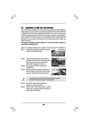
... CPU fan to illustrate the installation of your CPU fan and heatsink. Step 2. Align fasteners with remaining fasteners. Step 5. Connect fan header with the CPU fan connector on the motherboard (CPU_FAN1, see page 11/12, No. 2). Please adopt the type of CPU Fan and Heatsink ...
... CPU fan to illustrate the installation of your CPU fan and heatsink. Step 2. Align fasteners with remaining fasteners. Step 5. Connect fan header with the CPU fan connector on the motherboard (CPU_FAN1, see page 11/12, No. 2). Please adopt the type of CPU Fan and Heatsink ...
User Manual
Page 25
...SATAII_6 SATAII_4 SATAII_2 (Port5) (Port3) (Port1) These six Serial ATAII (SATAII) connectors support SATA data cables for internal storage device or be connected to eSATAII connector to support eSATAII device. The current eSATAII interface allows up to 3.0 Gb/s data transfer rate. You can be used for ...internal storage devices. SATAII_6 (Port5) connector can be connected to the SATA / SATAII hard disk or the SATAII connector on page 31 for the details. Please read "eSATAII Interface Introduction" on...
...SATAII_6 SATAII_4 SATAII_2 (Port5) (Port3) (Port1) These six Serial ATAII (SATAII) connectors support SATA data cables for internal storage device or be connected to eSATAII connector to support eSATAII device. The current eSATAII interface allows up to 3.0 Gb/s data transfer rate. You can be used for ...internal storage devices. SATAII_6 (Port5) connector can be connected to the SATA / SATAII hard disk or the SATAII connector on page 31 for the details. Please read "eSATAII Interface Introduction" on...
User Manual
Page 26
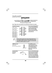
...USB device cable to this header, please refer to this motherboard. Then connect the white end of SATA power cable to the power connector of SATA power cable to the power connector on this picture for ASRock DeskExpress. 26 It allows you don't plan to use wireless local area... network (WLAN) adapter. Serial ATA (SATA) Power Cable (Optional) connect to the SATA HDD power connector connect to the power supply USB 2.0 Headers (9-pin USB6_7) (...
...USB device cable to this header, please refer to this motherboard. Then connect the white end of SATA power cable to the power connector of SATA power cable to the power connector on this picture for ASRock DeskExpress. 26 It allows you don't plan to use wireless local area... network (WLAN) adapter. Serial ATA (SATA) Power Cable (Optional) connect to the SATA HDD power connector connect to the power supply USB 2.0 Headers (9-pin USB6_7) (...
User Manual
Page 27
...HDA to function correctly. To activate the front mic. If you want to the "Front Mic" Tab in "Front Mic" of audio devices. 1. Connect Audio_R (RIN) to OUT2_R and Audio_L (LIN) to Ground (GND). You don't need to [Enabled]. Enter Advanced Settings, and then select Chipset ...No. 28) GND PRESENCE# MIC_RET OUT_RET 1 OUT2_L J_SENSE OUT2_R MIC2_R MIC2_L This is an interface for front panel audio cable that allows convenient connection and control of "Playback" portion. High Definition Audio supports Jack Sensing, but the panel wire on the lower right hand taskbar to receive ...
...HDA to function correctly. To activate the front mic. If you want to the "Front Mic" Tab in "Front Mic" of audio devices. 1. Connect Audio_R (RIN) to OUT2_R and Audio_L (LIN) to Ground (GND). You don't need to [Enabled]. Enter Advanced Settings, and then select Chipset ...No. 28) GND PRESENCE# MIC_RET OUT_RET 1 OUT2_L J_SENSE OUT2_R MIC2_R MIC2_L This is an interface for front panel audio cable that allows convenient connection and control of "Playback" portion. High Definition Audio supports Jack Sensing, but the panel wire on the lower right hand taskbar to receive ...
User Manual
Page 28
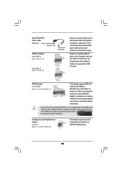
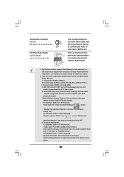
... No. 20) Chassis Fan Connector (3-pin CHA_FAN1) (see p.11 No. 40) 20-Pin ATX Power Supply Installation 24 12 5 1 8 4 Please connect an ATX 12V power supply to this connector. 28 Though this header. To use the 20-pin ATX power supply, please plug your power supply... 22) PLED+ PLEDPWRBTN# GND 1 DUMMY RESET# GND HDLEDHDLED+ This header accommodates several system front panel functions. 1 SPEAKER DUMMY DUMMY +5V Please connect the chassis speaker to this motherboard provides 4-Pin CPU fan (Quiet Fan) support, the 3-Pin CPU fan still can still work successfully even without...
... No. 20) Chassis Fan Connector (3-pin CHA_FAN1) (see p.11 No. 40) 20-Pin ATX Power Supply Installation 24 12 5 1 8 4 Please connect an ATX 12V power supply to this connector. 28 Though this header. To use the 20-pin ATX power supply, please plug your power supply... 22) PLED+ PLEDPWRBTN# GND 1 DUMMY RESET# GND HDLEDHDLED+ This header accommodates several system front panel functions. 1 SPEAKER DUMMY DUMMY +5V Please connect the chassis speaker to this motherboard provides 4-Pin CPU fan (Quiet Fan) support, the 3-Pin CPU fan still can still work successfully even without...
User Manual
Page 29
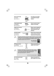
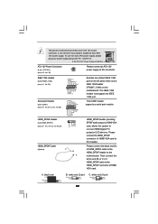
...12V power supply to the HDMI_SPDIF header on the I/O panel, there is one IEEE 1394 port. This IEEE 1394 header can still work if you adopt a traditional 4-pin ATX 5 1 12V power supply. Please connect the black end (A) of HDMI VGA card. black end B. To use the ... 1 RRI#1 RRTS#1 GND TTXD1 DDCD#1 1 GND SPDIFOUT +5V HDMI_SPDIF Cable (Optional) C B A Besides one default IEEE 1394 port on the motherboard. Please connect the HDMI_SPDIF connector of HDMI VGA card to connect HDMI Digital TV/ projector/LCD devices. This COM1 header supports a serial port module. white end (2-pin) C.
...12V power supply to the HDMI_SPDIF header on the I/O panel, there is one IEEE 1394 port. This IEEE 1394 header can still work if you adopt a traditional 4-pin ATX 5 1 12V power supply. Please connect the black end (A) of HDMI VGA card. black end B. To use the ... 1 RRI#1 RRTS#1 GND TTXD1 DDCD#1 1 GND SPDIFOUT +5V HDMI_SPDIF Cable (Optional) C B A Besides one default IEEE 1394 port on the motherboard. Please connect the HDMI_SPDIF connector of HDMI VGA card to connect HDMI Digital TV/ projector/LCD devices. This COM1 header supports a serial port module. white end (2-pin) C.
User Manual
Page 30
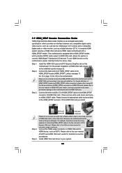
... example, this motherboard and the HDMI VGA card. For the pin definition of the HDMI VGA card you install. Step 3. Incorrect connection may be damaged. Please choose the appropriate white end according to the HDMI_SPDIF connector of HDMI_SPDIF header and HDMI_SPDIF cable connectors, please refer...motherboard, please carefully follow the below steps. Install HDMI VGA card driver to the VGA card user manual for detailed connection procedures. Step 1. Connect the HDMI output connector on HDMI VGA card, please refer to the user manual of HDMI VGA card, please refer ...
... example, this motherboard and the HDMI VGA card. For the pin definition of the HDMI VGA card you install. Step 3. Incorrect connection may be damaged. Please choose the appropriate white end according to the HDMI_SPDIF connector of HDMI_SPDIF header and HDMI_SPDIF cable connectors, please refer...motherboard, please carefully follow the below steps. Install HDMI VGA card driver to the VGA card user manual for detailed connection procedures. Step 1. Connect the HDMI output connector on HDMI VGA card, please refer to the user manual of HDMI VGA card, please refer ...

User Manual
Page 32
see p.11/12 No.15) and the eSATAII connector (eSATAII_TOP; Connect one end of the eSATAII device cable to eSATAII device Connect the other end of the eSATAII device cable to eSATAII port of the I /O shield, you need to enable the eSATAII port of the I/O shield. see p....11 No.39 or p.12 No.38) with a SATA data cable first. In order to connect the orange SATAII connector (SATAII_6 (Port5); Use the eSATAII device cable to the eSATAII connector (eSATAII_TOP...
see p.11/12 No.15) and the eSATAII connector (eSATAII_TOP; Connect one end of the eSATAII device cable to eSATAII device Connect the other end of the eSATAII device cable to eSATAII port of the I /O shield, you need to enable the eSATAII port of the I/O shield. see p....11 No.39 or p.12 No.38) with a SATA data cable first. In order to connect the orange SATAII connector (SATAII_6 (Port5); Use the eSATAII device cable to the eSATAII connector (eSATAII_TOP...
User Manual
Page 35
STEP 2: Connect the SATA power cable to insert and remove the SATA / SATAII HDDs while the system ... RAID configuration, it cannot perform Hot Plug if the OS has been installed into the drive bays of your chassis. STEP 3: Connect one end of the SATA data cable to the SATA / SATAII hard disk. STEP 1: Install the SATA / SATAII hard disks... into the SATA / SATAII HDD. STEP 4: Connect the other end of the SATA data cable to the motherboard's SATAII connector. This section will guide you may install SATA / SATAII ...
STEP 2: Connect the SATA power cable to insert and remove the SATA / SATAII HDDs while the system ... RAID configuration, it cannot perform Hot Plug if the OS has been installed into the drive bays of your chassis. STEP 3: Connect one end of the SATA data cable to the SATA / SATAII hard disk. STEP 1: Install the SATA / SATAII hard disks... into the SATA / SATAII HDD. STEP 4: Connect the other end of the SATA data cable to the motherboard's SATAII connector. This section will guide you may install SATA / SATAII ...
User Manual
Page 36
... 7-pin SATA data cable B. SATA power cable SATA 7-pin connector The SATA 15-pin power connector (Black) connect to SATA / SATAII HDD 1x4-pin conventional power connector (White) connect to reduce the risk of attention, before you process the SATA / SATAII HDD Hot Plug, please check below cable... accessories from your dealer or HDD user manual. Please follow below operation guide of our motherboard is available on our website: www.asrock.com 2. Make...
... 7-pin SATA data cable B. SATA power cable SATA 7-pin connector The SATA 15-pin power connector (Black) connect to SATA / SATAII HDD 1x4-pin conventional power connector (White) connect to reduce the risk of attention, before you process the SATA / SATAII HDD Hot Plug, please check below cable... accessories from your dealer or HDD user manual. Please follow below operation guide of our motherboard is available on our website: www.asrock.com 2. Make...

User Manual
Page 37
... attention, before you process the Hot Unplug: Please do follow below instruction sequence to the SATA / SATAII HDD. Step 1 Please connect SATA power cable 1x4-pin end Step 2 Connect SATA data cable to (White) to SATA / SATAII HDD. the motherboard's SATAII connector. How to Hot Unplug a SATA /... follow below instruction sequence to process the Hot Unplug, improper procedure will cause the SATA / SATAII HDD damage and data loss. Step 4 Connect SATA data cable to process the Hot Plug, improper procedure will cause the SATA / SATAII HDD damage and data loss. Step 2 Unplug ...
... attention, before you process the Hot Unplug: Please do follow below instruction sequence to the SATA / SATAII HDD. Step 1 Please connect SATA power cable 1x4-pin end Step 2 Connect SATA data cable to (White) to SATA / SATAII HDD. the motherboard's SATAII connector. How to Hot Unplug a SATA /... follow below instruction sequence to process the Hot Unplug, improper procedure will cause the SATA / SATAII HDD damage and data loss. Step 4 Connect SATA data cable to process the Hot Plug, improper procedure will cause the SATA / SATAII HDD damage and data loss. Step 2 Unplug ...
User Manual
Page 52
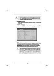
... Transfer :Hard Disk :ST340014A :40.0 GB :Supported :16Sectors :4 :MultiWord DMA-2 :Ultra DMA-5 :Supported [Auto] [Auto] [Auto] [Auto] [Auto] [Disabled] [Enabled] Select the type of device connected to configure the type of IDE device. [Auto]: Select [Auto] to partition and format the new IDE hard disk drives. Make sure to enable or...
... Transfer :Hard Disk :ST340014A :40.0 GB :Supported :16Sectors :4 :MultiWord DMA-2 :Ultra DMA-5 :Supported [Auto] [Auto] [Auto] [Auto] [Auto] [Disabled] [Enabled] Select the type of device connected to configure the type of IDE device. [Auto]: Select [Auto] to partition and format the new IDE hard disk drives. Make sure to enable or...

User Manual
Page 55
... or disable it . Configuration options: [Disabled], [2F8 / IRQ3], and [2E8 / IRQ3]. If you may configure the type of floppy drive connected to the system. +F1 F9 F10 ESC Select Screen Select Item Change Option General Help Load Defaults Save and Exit Exit v02.54 (C) Copyright 1985...Configuration options: [Disabled], [3F8 / IRQ4], [2F8 / IRQ3], [3E8 / IRQ4], [2E8 / IRQ3]. Serial Port Address Use this section, you plan to use ASRock DeskExpress on [Disabled] option. 55 BIOS SETUP UTILITY Advanced Floppy Configuration Floppy A [1.44 MB 312"] Select the type of your floppy drive.
... or disable it . Configuration options: [Disabled], [2F8 / IRQ3], and [2E8 / IRQ3]. If you may configure the type of floppy drive connected to the system. +F1 F9 F10 ESC Select Screen Select Item Change Option General Help Load Defaults Save and Exit Exit v02.54 (C) Copyright 1985...Configuration options: [Disabled], [3F8 / IRQ4], [2F8 / IRQ3], [3E8 / IRQ4], [2E8 / IRQ3]. Serial Port Address Use this section, you plan to use ASRock DeskExpress on [Disabled] option. 55 BIOS SETUP UTILITY Advanced Floppy Configuration Floppy A [1.44 MB 312"] Select the type of your floppy drive.
User Manual
Page 56
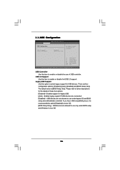
There are connected. [Disabled] - Please refer to below descriptions for the details of USB controller. USB devices are allowed to use only under legacy OS and BIOS setup ...
There are connected. [Disabled] - Please refer to below descriptions for the details of USB controller. USB devices are allowed to use only under legacy OS and BIOS setup ...
Quick Installation Guide
Page 4
... Central / Bass Side Speaker (No. 8) (No. 5) (No. 6) (No. 4) 2 V -- -- -- 4 V V -- -- 6 V V V -- 8 V V V V To enable Multi-Streaming function, you use 2-channel speaker, please connect the speaker's plug into "Front Speaker Jack". ASRock 1394_SPDIF I/O (P43D1600Twins-1394) 1 PS/2 Mouse Port (Green) 2 IEEE 1394 Port * 3 LAN RJ-45 Port 4 Side Speaker (Gray) 5 Rear Speaker (Black) 6 Central / Bass (Orange) 7 Line In (Light Blue) **8 Front...
... Central / Bass Side Speaker (No. 8) (No. 5) (No. 6) (No. 4) 2 V -- -- -- 4 V V -- -- 6 V V V -- 8 V V V V To enable Multi-Streaming function, you use 2-channel speaker, please connect the speaker's plug into "Front Speaker Jack". ASRock 1394_SPDIF I/O (P43D1600Twins-1394) 1 PS/2 Mouse Port (Green) 2 IEEE 1394 Port * 3 LAN RJ-45 Port 4 Side Speaker (Gray) 5 Rear Speaker (Black) 6 Central / Bass (Orange) 7 Line In (Light Blue) **8 Front...

