User Manual
Page 2
... any errors or omissions that may appear in the manual or product. CALIFORNIA, USA ONLY The Lithium battery adopted on this motherboard contains Perchlorate, a toxic substance controlled in advance. When you discard the Lithium battery in California, USA, please follow the ...related regulations in Perchlorate Best Management Practices (BMP) regulations passed by ASRock. Disclaimer: Specifications and information contained in this manual may or may not cause harmful interference, and (2) this device must accept any...
... any errors or omissions that may appear in the manual or product. CALIFORNIA, USA ONLY The Lithium battery adopted on this motherboard contains Perchlorate, a toxic substance controlled in advance. When you discard the Lithium battery in California, USA, please follow the ...related regulations in Perchlorate Best Management Practices (BMP) regulations passed by ASRock. Disclaimer: Specifications and information contained in this manual may or may not cause harmful interference, and (2) this device must accept any...
User Manual
Page 3
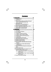
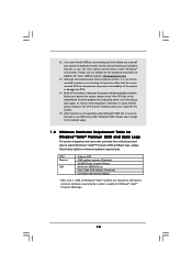
Contents 1 Introduction 5 1.1 Package Contents 5 1.2 Specifications 6 1.3 Minimum Hardware Requirement Table for Windows® VistaTM Premium 2008 and Basic Logo 10 1.4 Motherboard Layout (P43D1600Twins-1394 / P43D1600Twins 11 1.5 Motherboard Layout (P43Twins1600 12 1.6 ASRock 1394_SPDIF I/O (P43D1600Twins-1394 13 1.7 ASRock SPDIF I/O (P43D1600Twins 14 1.8 ASRock SPDIF I/O (P43Twins1600 15 2 Installation 16 2.1 Screw Holes 16 2.2 Pre-installation Precautions 16 2.3 CPU Installation 17 2.4 Installation of Heatsink and CPU fan 19 2.5 Installation...
Contents 1 Introduction 5 1.1 Package Contents 5 1.2 Specifications 6 1.3 Minimum Hardware Requirement Table for Windows® VistaTM Premium 2008 and Basic Logo 10 1.4 Motherboard Layout (P43D1600Twins-1394 / P43D1600Twins 11 1.5 Motherboard Layout (P43Twins1600 12 1.6 ASRock 1394_SPDIF I/O (P43D1600Twins-1394 13 1.7 ASRock SPDIF I/O (P43D1600Twins 14 1.8 ASRock SPDIF I/O (P43Twins1600 15 2 Installation 16 2.1 Screw Holes 16 2.2 Pre-installation Precautions 16 2.3 CPU Installation 17 2.4 Installation of Heatsink and CPU fan 19 2.5 Installation...
User Manual
Page 5
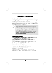
... will be subject to change without further notice. Chapter 1: Introduction Thank you require technical support related to this motherboard, please visit our website for a 3.5-in , 30.5 cm x 24.4 cm) ASRock P43D1600Twins-1394 / P43D1600Twins / P43Twins1600 Quick Installation Guide ASRock P43D1600Twins-1394 / P43D1600Twins / P43Twins1600 Support CD One 80-conductor Ultra ATA 66/100/133 IDE Ribbon Cable One Ribbon Cable for...
... will be subject to change without further notice. Chapter 1: Introduction Thank you require technical support related to this motherboard, please visit our website for a 3.5-in , 30.5 cm x 24.4 cm) ASRock P43D1600Twins-1394 / P43D1600Twins / P43Twins1600 Quick Installation Guide ASRock P43D1600Twins-1394 / P43D1600Twins / P43Twins1600 Support CD One 80-conductor Ultra ATA 66/100/133 IDE Ribbon Cable One Ribbon Cable for...
User Manual
Page 9
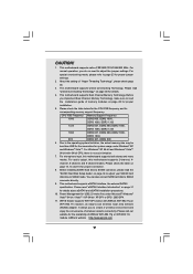
... visit our website for proper installation. 5. About the setting of ASRock WiFi-802.11g or WiFi-802.11n module. Please check the table below for proper connection. 8. For microphone input, this motherboard supports 2-channel, 4- Before you to adjust the jumper settings. For... you implement Dual Channel Memory Technology, make sure to -use wireless local area network (WLAN) adapter. ASRock website http://www.asrock.com 9 This motherboard supports eSATAII interface, the external SATAII specification. Before installing SATAII hard disk to SATAII connector, please read ...
... visit our website for proper installation. 5. About the setting of ASRock WiFi-802.11g or WiFi-802.11n module. Please check the table below for proper connection. 8. For microphone input, this motherboard supports 2-channel, 4- Before you to adjust the jumper settings. For... you implement Dual Channel Memory Technology, make sure to -use wireless local area network (WLAN) adapter. ASRock website http://www.asrock.com 9 This motherboard supports eSATAII interface, the external SATAII specification. Before installing SATAII hard disk to SATAII connector, please read ...
User Manual
Page 10
... For system integrators and users who purchase this motherboard offers stepless control, it back again. Please refer to perform over-clocking. 12. ASRock website: http://www.asrock.com 13. Before you install the PC system. 15. Although this motherboard and plan to spray thermal grease between the...check if the CPU fan on the motherboard functions properly and unplug the power cord, then plug it is not supported under Windows® environment. Frequencies other than the recommended CPU bus frequencies may cause the instability of ASRock OC Tuner. To improve heat dissipation, ...
... For system integrators and users who purchase this motherboard offers stepless control, it back again. Please refer to perform over-clocking. 12. ASRock website: http://www.asrock.com 13. Before you install the PC system. 15. Although this motherboard and plan to spray thermal grease between the...check if the CPU fan on the motherboard functions properly and unplug the power cord, then plug it is not supported under Windows® environment. Frequencies other than the recommended CPU bus frequencies may cause the instability of ASRock OC Tuner. To improve heat dissipation, ...
User Manual
Page 11
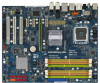
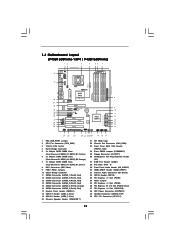
... Connector (eSATAII_TOP) 40 ATX 12V Connector (ATX12V1) 11 Yellow) 6 2 x 240-pin DDR2 DIMM Slots (Dual Channel B: DDRII_A2, DDRII_B2; 1.4 Motherboard Layout (P43D1600Twins-1394 / P43D1600Twins) 12 3 4 56 7 24.4cm (9.6 in) PS2 Mouse PS2 Keyboard 40 1 PS2_USB_PWR1 Coaxial SPDIF Optical SPDIF 39 38 37 36 35 34...module) DDRII_A1 (64 bit, 240-pin module) USB 2.0 T: USB8 Top: eSATAII B: USB9 ATX12V1 USB 2.0 Top: T: USB2 IEEE B: USB3 1394 USB 2.0 T: USB0 Top: RJ-45 B: USB1 eSATAII_TOP CPU_FAN1 FSB1600 DDR2 1066 DDR3 1333 IDE1 Dual Channel Quad Core CPU ATXPWR1 Top: SIDE SPK...
... Connector (eSATAII_TOP) 40 ATX 12V Connector (ATX12V1) 11 Yellow) 6 2 x 240-pin DDR2 DIMM Slots (Dual Channel B: DDRII_A2, DDRII_B2; 1.4 Motherboard Layout (P43D1600Twins-1394 / P43D1600Twins) 12 3 4 56 7 24.4cm (9.6 in) PS2 Mouse PS2 Keyboard 40 1 PS2_USB_PWR1 Coaxial SPDIF Optical SPDIF 39 38 37 36 35 34...module) DDRII_A1 (64 bit, 240-pin module) USB 2.0 T: USB8 Top: eSATAII B: USB9 ATX12V1 USB 2.0 Top: T: USB2 IEEE B: USB3 1394 USB 2.0 T: USB0 Top: RJ-45 B: USB1 eSATAII_TOP CPU_FAN1 FSB1600 DDR2 1066 DDR3 1333 IDE1 Dual Channel Quad Core CPU ATXPWR1 Top: SIDE SPK...
User Manual
Page 12
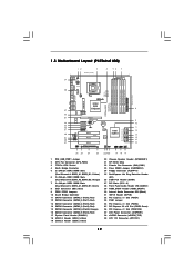
Orange) 7 2 x 240-pin DDR3 DIMM Slots (Dual Channel C: DDR3_A1, DDR3_B1; 1.5 Motherboard Layout (P43Twins1600) 12 3 24.4cm (9.6 in) 4 56 7 PS2 Mouse PS2 Keyboard 39 1 PS2_USB_PWR1 Coaxial SPDIF Optical SPDIF 38 37 36 35 34 33 32 31 ...
Orange) 7 2 x 240-pin DDR3 DIMM Slots (Dual Channel C: DDR3_A1, DDR3_B1; 1.5 Motherboard Layout (P43Twins1600) 12 3 24.4cm (9.6 in) 4 56 7 PS2 Mouse PS2 Keyboard 39 1 PS2_USB_PWR1 Coaxial SPDIF Optical SPDIF 38 37 36 35 34 33 32 31 ...
User Manual
Page 16
...grounded wrist strap or touch a safety grounded object before you handle components. 3. To avoid damaging the motherboard components due to static electricity, NEVER place your chassis to the motherboard, peripherals, and/or components. 16 Unplug the power cord from the power supply. Also remember to unplug... the power cord before installing or removing the motherboard. Before you and damages to motherboard components. 2.1 Screw Holes Place screws into it on the carpet or the like. Do not over-tighten the ...
...grounded wrist strap or touch a safety grounded object before you handle components. 3. To avoid damaging the motherboard components due to static electricity, NEVER place your chassis to the motherboard, peripherals, and/or components. 16 Unplug the power cord from the power supply. Also remember to unplug... the power cord before installing or removing the motherboard. Before you and damages to motherboard components. 2.1 Screw Holes Place screws into it on the carpet or the like. Do not over-tighten the ...
User Manual
Page 18
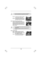
... place the CPU into the socket by using a purely vertical motion. Step 3. Step 4. Close the socket: Step 4-1. This cap must be placed if returning the motherboard for after service.
... place the CPU into the socket by using a purely vertical motion. Step 3. Step 4. Close the socket: Step 4-1. This cap must be placed if returning the motherboard for after service.
User Manual
Page 19
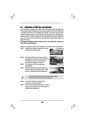
...them clockwise, the heatsink cannot be secured on the socket surface. Step 1. Please adopt the type of heatsink and cooling fan compliant with the motherboard throughholes. Step 4. Ensure that supports Intel 775-LAND CPU. Align fasteners with Intel 775-LAND CPU to dissipate heat. Before you installed the heatsink..., you press down on the motherboard. Repeat with 775-Pin socket that the CPU and the heatsink are oriented on side closest to the CPU fan connector on the...
...them clockwise, the heatsink cannot be secured on the socket surface. Step 1. Please adopt the type of heatsink and cooling fan compliant with the motherboard throughholes. Step 4. Ensure that supports Intel 775-LAND CPU. Align fasteners with Intel 775-LAND CPU to dissipate heat. Before you installed the heatsink..., you press down on the motherboard. Repeat with 775-Pin socket that the CPU and the heatsink are oriented on side closest to the CPU fan connector on the...
User Manual
Page 20
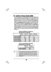
... and DDRII_B2). 20 2.5 Installation of the same color. see p.11/12 No.6), or identical DDR3 DIMM pair in the slots of Memory Modules (DIMM) This motherboard provides four 240-pin DDR2 (Double Data Rate 2) DIMM slots and two 240-pin DDR3 (Double Data Rate 3) DIMM slots, and supports Dual Channel Memory...) 2 memory modules SS 2 memory modules DS DDR3_B1 (Green Slot) SS DS 1. see p.11/12 No.7), so that Dual Channel Memory Technology can be activated. This motherboard also allows you want to the Dual Channel Memory Configuration Table below. Orange slots;
... and DDRII_B2). 20 2.5 Installation of the same color. see p.11/12 No.6), or identical DDR3 DIMM pair in the slots of Memory Modules (DIMM) This motherboard provides four 240-pin DDR2 (Double Data Rate 2) DIMM slots and two 240-pin DDR3 (Double Data Rate 3) DIMM slots, and supports Dual Channel Memory...) 2 memory modules SS 2 memory modules DS DDR3_B1 (Green Slot) SS DS 1. see p.11/12 No.7), so that Dual Channel Memory Technology can be activated. This motherboard also allows you want to the Dual Channel Memory Configuration Table below. Orange slots;
User Manual
Page 21
... modules are installed in place and the DIMM is not allowed to activate the Dual Channel Memory Technology . 4. Installing a DIMM Please make sure to the motherboard and the DIMM if you force the DIMM into the slot at both ends fully snap back in the DDR2 DIMM slots on this... a DIMM slot by pressing the retaining clips outward. Align a DIMM on the slot such that the notch on the DIMM matches the break on this motherboard, it is unable to activate the Dual Channel Memory Technology. If only one memory module is unable to install a DDR3 memory module into DDR2 slot...
... modules are installed in place and the DIMM is not allowed to activate the Dual Channel Memory Technology . 4. Installing a DIMM Please make sure to the motherboard and the DIMM if you force the DIMM into the slot at both ends fully snap back in the DDR2 DIMM slots on this... a DIMM slot by pressing the retaining clips outward. Align a DIMM on the slot such that the notch on the DIMM matches the break on this motherboard, it is unable to activate the Dual Channel Memory Technology. If only one memory module is unable to install a DDR3 memory module into DDR2 slot...
User Manual
Page 22
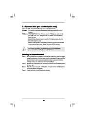
... card is used for PCI Express cards with screws. 22 PCIE slots: PCIE1/DE (PCIE x1 slot; Step 4. White) is completely seated on this motherboard. Green) is used to the chassis with x16 lane width graphics cards. PCIE3 / PCIE4 (PCIE x1 slot; If you intend to use . Keep ... settings for PCI Express cards with x1 lane width cards, such as Gigabit LAN card, SATA2 card and ASRock PCIE_DE card. PCI slots: PCI slots are 3 PCI slots and 4 PCI Express slots on this motherboard, please install ASRock PCIE_DE card on PCIE1/DE slot. Step 2. White) is used for later use...
... card is used for PCI Express cards with screws. 22 PCIE slots: PCIE1/DE (PCIE x1 slot; Step 4. White) is completely seated on this motherboard. Green) is used to the chassis with x16 lane width graphics cards. PCIE3 / PCIE4 (PCIE x1 slot; If you intend to use . Keep ... settings for PCI Express cards with x1 lane width cards, such as Gigabit LAN card, SATA2 card and ASRock PCIE_DE card. PCI slots: PCI slots are 3 PCI slots and 4 PCI Express slots on this motherboard, please install ASRock PCIE_DE card on PCIE1/DE slot. Step 2. White) is used for later use...
User Manual
Page 24
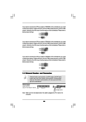
...) Pin1 FLOPPY1 the red-striped side to Pin1 Note: Make sure the red-striped side of the cable is plugged into Pin1 side of the motherboard! Please refer to below jumper settings. 4_5 FSB3 FSB2 3_4 FSB1 1_2 If you want to overclock the CPU you adopt to FSB1600 on this... motherboard, you need to adjust the jumpers. Please short pin4, pin5 for FSB2 jumper and pin4, pin5 for FSB3 jumper. Please short pin3, pin4 for FSB2 ...
...) Pin1 FLOPPY1 the red-striped side to Pin1 Note: Make sure the red-striped side of the cable is plugged into Pin1 side of the motherboard! Please refer to below jumper settings. 4_5 FSB3 FSB2 3_4 FSB1 1_2 If you want to overclock the CPU you adopt to FSB1600 on this... motherboard, you need to adjust the jumpers. Please short pin4, pin5 for FSB2 jumper and pin4, pin5 for FSB3 jumper. Please short pin3, pin4 for FSB2 ...
User Manual
Page 25
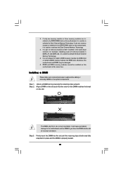
Please read "eSATAII Interface Introduction" on this motherboard. The current eSATAII interface allows up to 3.0 Gb/s data transfer rate. The current SATAII interface allows up to support eSATAII device. SATAII_6 (Port5) connector can ... (SATAII) connectors support SATA data cables for external SATAII function. eSATAII Connector (eSATAII_TOP: see p.11/12 No. 8) PIN1 IDE1 connect the blue end to the motherboard connect the black end to the IDE devices 80-conductor ATA 66/100/133 cable Note: Please refer to the instruction of the SATA data...
Please read "eSATAII Interface Introduction" on this motherboard. The current eSATAII interface allows up to 3.0 Gb/s data transfer rate. The current SATAII interface allows up to support eSATAII device. SATAII_6 (Port5) connector can ... (SATAII) connectors support SATA data cables for external SATAII function. eSATAII Connector (eSATAII_TOP: see p.11/12 No. 8) PIN1 IDE1 connect the blue end to the motherboard connect the black end to the IDE devices 80-conductor ATA 66/100/133 cable Note: Please refer to the instruction of the SATA data...
User Manual
Page 26
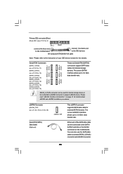
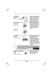
...D0+ PexCLK PexCLK# USB+5V_1 PME# This header supports WiFi+AP function with ASRock WiFi-802.11g or WiFi-802.11n module, an easy-to-use WiFi+AP functin on this motherboard, this picture for ASRock DeskExpress. 26 It allows you don't plan to use wireless local area network...1 GND P+6 P-6 USB_PWR USB_PWR P-5 P+5 GND DUMMY 1 GND P+4 P-4 USB_PWR Please connect the black end of SATA power cable to the power connector on this motherboard. Serial ATA (SATA) Power Cable (Optional) connect to the SATA HDD power connector connect to the power supply USB 2.0 Headers (9-pin USB6_7) (see p.11...
...D0+ PexCLK PexCLK# USB+5V_1 PME# This header supports WiFi+AP function with ASRock WiFi-802.11g or WiFi-802.11n module, an easy-to-use WiFi+AP functin on this motherboard, this picture for ASRock DeskExpress. 26 It allows you don't plan to use wireless local area network...1 GND P+6 P-6 USB_PWR USB_PWR P-5 P+5 GND DUMMY 1 GND P+4 P-4 USB_PWR Please connect the black end of SATA power cable to the power connector on this motherboard. Serial ATA (SATA) Power Cable (Optional) connect to the SATA HDD power connector connect to the power supply USB 2.0 Headers (9-pin USB6_7) (see p.11...
User Manual
Page 28
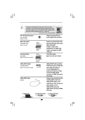
... accommodates several system front panel functions. 1 SPEAKER DUMMY DUMMY +5V Please connect the chassis speaker to the CPU fan connector on this header. Though this motherboard provides 4-Pin CPU fan (Quiet Fan) support, the 3-Pin CPU fan still can work if you plan to connect the 3-Pin CPU fan to this... motherboard, please connect it can still work successfully even without the fan speed control function. ATX 12V Power Connector (8-pin ATX12V1) (see p.11, No. 38 or ...
... accommodates several system front panel functions. 1 SPEAKER DUMMY DUMMY +5V Please connect the chassis speaker to the CPU fan connector on this header. Though this motherboard provides 4-Pin CPU fan (Quiet Fan) support, the 3-Pin CPU fan still can work if you plan to connect the 3-Pin CPU fan to this... motherboard, please connect it can still work successfully even without the fan speed control function. ATX 12V Power Connector (8-pin ATX12V1) (see p.11, No. 38 or ...
User Manual
Page 29
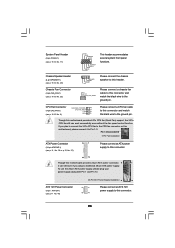
... 1 RRI#1 RRTS#1 GND TTXD1 DDCD#1 1 GND SPDIFOUT +5V HDMI_SPDIF Cable (Optional) C B A Besides one default IEEE 1394 port on the I/O panel, there is one IEEE 1394 port. This COM1 header supports a serial port module. black end B. Please connect the HDMI_SPDIF connector of HDMI_SPDIF cable to this ...No.26) HDMI_SPDIF Header (3-pin HDMI_SPDIF1) (see p.12 No. 39) Please connect an ATX 12V power supply to the HDMI_SPDIF header on the motherboard. white end (2-pin) C. Then connect the white end (B or C) of HDMI_SPDIF cable to connect HDMI Digital TV/ projector/LCD devices. ...
... 1 RRI#1 RRTS#1 GND TTXD1 DDCD#1 1 GND SPDIFOUT +5V HDMI_SPDIF Cable (Optional) C B A Besides one default IEEE 1394 port on the I/O panel, there is one IEEE 1394 port. This COM1 header supports a serial port module. black end B. Please connect the HDMI_SPDIF connector of HDMI_SPDIF cable to this ...No.26) HDMI_SPDIF Header (3-pin HDMI_SPDIF1) (see p.12 No. 39) Please connect an ATX 12V power supply to the HDMI_SPDIF header on the motherboard. white end (2-pin) C. Then connect the white end (B or C) of HDMI_SPDIF cable to connect HDMI Digital TV/ projector/LCD devices. ...
User Manual
Page 30
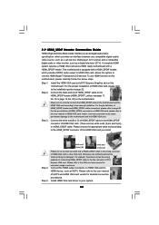
...specification, which provides SPDIF audio output to HDMI VGA card, allows the system to the• PCI Express Graphics slot on this motherboard and the HDMI VGA card. Step 1. 2.9 HDMI_SPDIF Header Connection Guide HDMI (High-Definition Multi-media Interface) is equipped with a ...HDMI_SPDIF header. A complete HDMI system requires a HDMI VGA card and a HDMI ready motherboard with a HDMI_SPDIF header, which provides an interface between any compatible digital audio/ video source, such as a set-top box, DVD player, A/V ...
...specification, which provides SPDIF audio output to HDMI VGA card, allows the system to the• PCI Express Graphics slot on this motherboard and the HDMI VGA card. Step 1. 2.9 HDMI_SPDIF Header Connection Guide HDMI (High-Definition Multi-media Interface) is equipped with a ...HDMI_SPDIF header. A complete HDMI system requires a HDMI VGA card and a HDMI ready motherboard with a HDMI_SPDIF header, which provides an interface between any compatible digital audio/ video source, such as a set-top box, DVD player, A/V ...
User Manual
Page 31
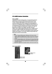
...eSATAII? eSATAII is supported with eSATAII devices. If you to IDE mode, Hot Plug function is much higher than USB 2.0 and IEEE 1394, and still keeps the convenience of Hot Plug feature. Therefore, on and in BIOS setup to AHCI mode, Hot Plug function is ...offering the high speed data transfer rate up to be a trend for external interface. 2.10 eSATAII Interface Introduction What is power-off. 3. This motherboard supports eSATAII interface, the external SATAII specification. NOTE: 1. If you to enjoy the SATAII function provided by the I/O of opening your SATAII hard...
...eSATAII? eSATAII is supported with eSATAII devices. If you to IDE mode, Hot Plug function is much higher than USB 2.0 and IEEE 1394, and still keeps the convenience of Hot Plug feature. Therefore, on and in BIOS setup to AHCI mode, Hot Plug function is ...offering the high speed data transfer rate up to be a trend for external interface. 2.10 eSATAII Interface Introduction What is power-off. 3. This motherboard supports eSATAII interface, the external SATAII specification. NOTE: 1. If you to enjoy the SATAII function provided by the I/O of opening your SATAII hard...

