
User Manual
Page 10
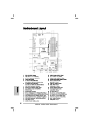
...bit, 240-pin module) DDR3_A1 (64 bit, 240-pin module) RJ-45 USB 2.0: USB4 eSATAII1 USB 3.0: USB5 P43 Pro/USB3 FSB1600 33 Top: SIDE SPK Center: REAR SPK Bottom: CTR BASS Intel P43 8 Top: LINE IN Center: FRONT Bottom: MIC IN Chipset CHA_FAN1 30.5cm (12.0 in) 32 31 30... (USB6_7, Blue) 2 ATX 12V Connector (ATX12V1) 20 Power LED Header (PLED1) 3 CPU Fan Connector (CPU_FAN1) 21 USB 2.0 Header (USB10_11, Blue) 4 775-Pin CPU Socket 22 System Panel Header (PANEL1, White) 5 2 x 240-pin DDR3 DIMM Slots 23 Chassis Speaker Header (Dual Channel: DDR3_A1, DDR3_B1; Blue) (SPEAKER 1, White...
...bit, 240-pin module) DDR3_A1 (64 bit, 240-pin module) RJ-45 USB 2.0: USB4 eSATAII1 USB 3.0: USB5 P43 Pro/USB3 FSB1600 33 Top: SIDE SPK Center: REAR SPK Bottom: CTR BASS Intel P43 8 Top: LINE IN Center: FRONT Bottom: MIC IN Chipset CHA_FAN1 30.5cm (12.0 in) 32 31 30... (USB6_7, Blue) 2 ATX 12V Connector (ATX12V1) 20 Power LED Header (PLED1) 3 CPU Fan Connector (CPU_FAN1) 21 USB 2.0 Header (USB10_11, Blue) 4 775-Pin CPU Socket 22 System Panel Header (PANEL1, White) 5 2 x 240-pin DDR3 DIMM Slots 23 Chassis Speaker Header (Dual Channel: DDR3_A1, DDR3_B1; Blue) (SPEAKER 1, White...

User Manual
Page 13
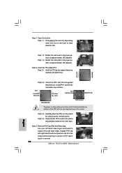
...CPU will be seriously damaged. Step 1-2. 2.3 CPU Installation For the installation of Intel 775-LAND CPU, please follow the steps below. 775-Pin Socket Overview Before you insert the 775-LAND CPU into the socket if above situation is any bent pin on the hook to fully open position at approximately... 100 degrees. Step 1-3. Orient the CPU with black lines. Hold the CPU by depressing down and out on the socket. Pin1 orientation key notch orientation key notch Pin1 alignment key alignment key 775-LAND CPU 775-Pin Socket 13 black line black line Step 1. Step 2.
...CPU will be seriously damaged. Step 1-2. 2.3 CPU Installation For the installation of Intel 775-LAND CPU, please follow the steps below. 775-Pin Socket Overview Before you insert the 775-LAND CPU into the socket if above situation is any bent pin on the hook to fully open position at approximately... 100 degrees. Step 1-3. Orient the CPU with black lines. Hold the CPU by depressing down and out on the socket. Pin1 orientation key notch orientation key notch Pin1 alignment key alignment key 775-LAND CPU 775-Pin Socket 13 black line black line Step 1. Step 2.
User Manual
Page 15
... clockwise, the heatsink cannot be secured on the motherboard. Secure excess cable with tie-wrap to ensure cable does not interfere with 775-Pin socket that the CPU and the heatsink are oriented on side closest to the CPU fan connector on the motherboard. Then connect the CPU... onto center of IHS on fastener caps with each other components. 15 Step 4. Place the heatsink onto the socket. Repeat with the motherboard throughholes. Ensure that supports Intel 775-LAND CPU. Step 5. Ensure fan cables are securely fastened and in good contact with thumb to install and lock...
... clockwise, the heatsink cannot be secured on the motherboard. Secure excess cable with tie-wrap to ensure cable does not interfere with 775-Pin socket that the CPU and the heatsink are oriented on side closest to the CPU fan connector on the motherboard. Then connect the CPU... onto center of IHS on fastener caps with each other components. 15 Step 4. Place the heatsink onto the socket. Repeat with the motherboard throughholes. Ensure that supports Intel 775-LAND CPU. Step 5. Ensure fan cables are securely fastened and in good contact with thumb to install and lock...
Quick Installation Guide
Page 2
... USB_PWR3 Jumper 34 USB_PWR2 Jumper 18 USB 2.0 Header (USB8_9, Blue) 2 ASRock P43 Pro/USB3 Motherboard Motherboard Layout English 1 PS2_USB_PWR1 Jumper 19 USB 2.0 Header (USB6_7, Blue) 2 ATX 12V Connector (ATX12V1) 20 Power LED Header (PLED1) 3 CPU Fan Connector (CPU_FAN1) 21 USB 2.0 Header (USB10_11, Blue) 4 775-Pin CPU Socket 22 System Panel Header (PANEL1, White) 5 2 x 240-pin DDR3...
... USB_PWR3 Jumper 34 USB_PWR2 Jumper 18 USB 2.0 Header (USB8_9, Blue) 2 ASRock P43 Pro/USB3 Motherboard Motherboard Layout English 1 PS2_USB_PWR1 Jumper 19 USB 2.0 Header (USB6_7, Blue) 2 ATX 12V Connector (ATX12V1) 20 Power LED Header (PLED1) 3 CPU Fan Connector (CPU_FAN1) 21 USB 2.0 Header (USB10_11, Blue) 4 775-Pin CPU Socket 22 System Panel Header (PANEL1, White) 5 2 x 240-pin DDR3...

Quick Installation Guide
Page 9
Otherwise, the CPU will be seriously damaged. 9 ASRock P43 Pro/USB3 Motherboard English To avoid damaging the motherboard components due to use a grounded wrist strap or touch a safety grounded object before you insert the 775-LAND CPU into the socket, please check if the CPU surface is unclean or if ... by the edges and do not over-tighten the screws! Installation Pre-installation Precautions Take note of Intel 775-LAND CPU, please follow the steps below. 775-Pin Socket Overview Before you handle components. 3. Do not force to insert the CPU into the screw holes to secure...
Otherwise, the CPU will be seriously damaged. 9 ASRock P43 Pro/USB3 Motherboard English To avoid damaging the motherboard components due to use a grounded wrist strap or touch a safety grounded object before you insert the 775-LAND CPU into the socket, please check if the CPU surface is unclean or if ... by the edges and do not over-tighten the screws! Installation Pre-installation Precautions Take note of Intel 775-LAND CPU, please follow the steps below. 775-Pin Socket Overview Before you handle components. 3. Do not force to insert the CPU into the screw holes to secure...
Quick Installation Guide
Page 10
... pressing on the hook to fully open position at approximately 100 degrees. Open the socket: Step 1-1. Disengaging the lever by depressing down and out on center of PnP cap to assist in removal. 10 ASRock P43 Pro/USB3 Motherboard Step 1-3. Hold the CPU by using a purely vertical motion. black line black line ...the load plate edge, engage PnP cap with black lines. Pin1 orientation key notch orientation key notch Pin1 alignment key alignment key 775-LAND CPU 775-Pin Socket For proper inserting, please ensure to the orient keys. Step 2-4. Verify that the CPU is within the...
... pressing on the hook to fully open position at approximately 100 degrees. Open the socket: Step 1-1. Disengaging the lever by depressing down and out on center of PnP cap to assist in removal. 10 ASRock P43 Pro/USB3 Motherboard Step 1-3. Hold the CPU by using a purely vertical motion. black line black line ...the load plate edge, engage PnP cap with black lines. Pin1 orientation key notch orientation key notch Pin1 alignment key alignment key 775-LAND CPU 775-Pin Socket For proper inserting, please ensure to the orient keys. Step 2-4. Verify that the CPU is within the...

Quick Installation Guide
Page 11
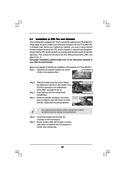
...on the motherboard. Place the heatsink onto the socket. Align fasteners with remaining fasteners. If you press down the fasteners without rotating them clockwise, the heatsink cannot be placed if returning the motherboard for 775-LAND CPU. Secure excess cable with thumb to... the socket: Step 4-1. Step 4-2. While pressing down on fastener caps with tie-wrap to illustrate the installation of your CPU fan and heatsink. Step 1. 1. It is an example to ensure cable does not interfere with fan operation or contact other components. 11 ASRock P43 Pro/USB3 Motherboard English...
...on the motherboard. Place the heatsink onto the socket. Align fasteners with remaining fasteners. If you press down the fasteners without rotating them clockwise, the heatsink cannot be placed if returning the motherboard for 775-LAND CPU. Secure excess cable with thumb to... the socket: Step 4-1. Step 4-2. While pressing down on fastener caps with tie-wrap to illustrate the installation of your CPU fan and heatsink. Step 1. 1. It is an example to ensure cable does not interfere with fan operation or contact other components. 11 ASRock P43 Pro/USB3 Motherboard English...