
User Manual
Page 11
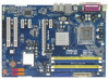
...CTR BASS Top: LINE IN Center: FRONT Bottom: MIC IN 1 FSB2 1 FSB3 Intel G41 Chipset PCIE1 EuP Ready LAN PCIE2 PHY RoHS P41C-DE IDE1 CHA_FAN1 SATAII_4 SATAII_2 Super IO PCIE3 PCIE4 Intel ICH7 SATAII_3 AUDIO CODEC HD_AUDIO1 1 HDMI_SPDIF1 1 FLOPPY1 PCI1 PCI2 1 IR1 8Mb BIOS CMOS...bit, 240-FpinSBmo8d0ul0e) 30.5cm (12.0 in) 5 6 7 8 9 10 11 12 13 14 1 PS2_USB_PWR1 Jumper 17 USB 2.0 Header (USB6_7, Blue) 2 775-Pin CPU Socket 18 BIOS SPI Chip 3 2 x 240-pin DDR2 DIMM Slots 19 USB 2.0 Header (USB4_5, Blue) (Dual Channel: DDRII_1, DDRII_2; Yellow) 20 Infrared Module ...
...CTR BASS Top: LINE IN Center: FRONT Bottom: MIC IN 1 FSB2 1 FSB3 Intel G41 Chipset PCIE1 EuP Ready LAN PCIE2 PHY RoHS P41C-DE IDE1 CHA_FAN1 SATAII_4 SATAII_2 Super IO PCIE3 PCIE4 Intel ICH7 SATAII_3 AUDIO CODEC HD_AUDIO1 1 HDMI_SPDIF1 1 FLOPPY1 PCI1 PCI2 1 IR1 8Mb BIOS CMOS...bit, 240-FpinSBmo8d0ul0e) 30.5cm (12.0 in) 5 6 7 8 9 10 11 12 13 14 1 PS2_USB_PWR1 Jumper 17 USB 2.0 Header (USB6_7, Blue) 2 775-Pin CPU Socket 18 BIOS SPI Chip 3 2 x 240-pin DDR2 DIMM Slots 19 USB 2.0 Header (USB4_5, Blue) (Dual Channel: DDRII_1, DDRII_2; Yellow) 20 Infrared Module ...

User Manual
Page 15
... orientation key notch orientation key notch Pin1 alignment key alignment key 775-LAND CPU 775-Pin Socket 15 2.3 CPU Installation For the installation of Intel 775-LAND CPU, please follow the steps below. 775-Pin Socket Overview Before you insert the 775-LAND CPU into the socket if above situation is any bent pin on the ShoockoetkMatrokedcCleoranerr retention...
... orientation key notch orientation key notch Pin1 alignment key alignment key 775-LAND CPU 775-Pin Socket 15 2.3 CPU Installation For the installation of Intel 775-LAND CPU, please follow the steps below. 775-Pin Socket Overview Before you insert the 775-LAND CPU into the socket if above situation is any bent pin on the ShoockoetkMatrokedcCleoranerr retention...

User Manual
Page 17
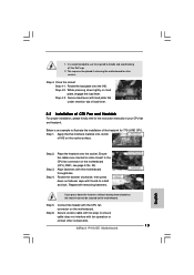
...and cooling fan compliant with each other components. 17 Connect fan header with 775-Pin socket that the CPU and the heatsink are oriented on side closest to illustrate the installation of IHS on the socket surface. 2.4 Installation of CPU Fan and Heatsink This motherboard is an ...are securely fastened and in good contact with Intel 775-LAND CPU to improve heat dissipation. If you need to spray thermal interface material between the CPU and the heatsink to dissipate heat. Place the heatsink onto the socket. Repeat with the motherboard throughholes. Before you installed...
...and cooling fan compliant with each other components. 17 Connect fan header with 775-Pin socket that the CPU and the heatsink are oriented on side closest to illustrate the installation of IHS on the socket surface. 2.4 Installation of CPU Fan and Heatsink This motherboard is an ...are securely fastened and in good contact with Intel 775-LAND CPU to improve heat dissipation. If you need to spray thermal interface material between the CPU and the heatsink to dissipate heat. Place the heatsink onto the socket. Repeat with the motherboard throughholes. Before you installed...
Quick Installation Guide
Page 2
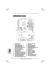
...29 FSB2 / FSB3 Jumper 13 Primary SATAII Connector (SATAII_1; Motherboard Layout English 1 PS2_USB_PWR1 Jumper 17 USB 2.0 Header (USB6_7, Blue) 2 775-Pin CPU Socket 18 BIOS SPI Chip 3 2 x 240-pin DDR2 DIMM Slots 19 USB 2.0 Header (USB4_5, Blue) (Dual Channel: DDRII_1, DDRII_2; ... 12V Connector (ATX12V1) 15 Clear CMOS Jumper (CLRCMOS1) 32 CPU Fan Connector (CPU_FAN1) 16 Chassis Speaker Header (SPEAKER 1, Purple) 2 ASRock P41C-DE Motherboard Orange) 27 PCI Express x16 Slot (PCIE2) 11 Fourth SATAII Connector (SATAII_4; Blue) 22 HDMI_SPDIF Header (HDMI_SPDIF1, Yellow) 5 ATX...
...29 FSB2 / FSB3 Jumper 13 Primary SATAII Connector (SATAII_1; Motherboard Layout English 1 PS2_USB_PWR1 Jumper 17 USB 2.0 Header (USB6_7, Blue) 2 775-Pin CPU Socket 18 BIOS SPI Chip 3 2 x 240-pin DDR2 DIMM Slots 19 USB 2.0 Header (USB4_5, Blue) (Dual Channel: DDRII_1, DDRII_2; ... 12V Connector (ATX12V1) 15 Clear CMOS Jumper (CLRCMOS1) 32 CPU Fan Connector (CPU_FAN1) 16 Chassis Speaker Header (SPEAKER 1, Purple) 2 ASRock P41C-DE Motherboard Orange) 27 PCI Express x16 Slot (PCIE2) 11 Fourth SATAII Connector (SATAII_4; Blue) 22 HDMI_SPDIF Header (HDMI_SPDIF1, Yellow) 5 ATX...

Quick Installation Guide
Page 11
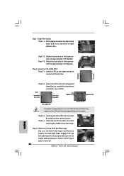
...if the CPU surface is unclean or if there is found. Installation Pre-installation Precautions Take note of Intel 775-LAND CPU, please follow the steps below. 775-Pin Socket Overview Before you uninstall any motherboard settings. 1. To avoid damaging the motherboard components due to the motherboard,.... Doing so may cause severe damage to static electricity, NEVER place your motherboard directly on the socket. Otherwise, the CPU will be seriously damaged. 11 ASRock P41C-DE Motherboard English Also remember to insert the CPU into the screw holes to secure the motherboard to the...
...if the CPU surface is unclean or if there is found. Installation Pre-installation Precautions Take note of Intel 775-LAND CPU, please follow the steps below. 775-Pin Socket Overview Before you uninstall any motherboard settings. 1. To avoid damaging the motherboard components due to the motherboard,.... Doing so may cause severe damage to static electricity, NEVER place your motherboard directly on the socket. Otherwise, the CPU will be seriously damaged. 11 ASRock P41C-DE Motherboard English Also remember to insert the CPU into the screw holes to secure the motherboard to the...
Quick Installation Guide
Page 12
...the two orientation key notches. Pin1 orientation key notch orientation key notch Pin1 alignment key alignment key 775-LAND CPU 775-Pin Socket For proper inserting, please ensure to assist in removal. 12 ASRock P41C-DE Motherboard Remove PnP Cap (Pick and Place Cap): Use your left hand index finger and thumb ...to support the load plate edge, engage PnP cap with the two alignment keys of the CPU with right hand thumb and peel the cap from the socket while pressing...
...the two orientation key notches. Pin1 orientation key notch orientation key notch Pin1 alignment key alignment key 775-LAND CPU 775-Pin Socket For proper inserting, please ensure to assist in removal. 12 ASRock P41C-DE Motherboard Remove PnP Cap (Pick and Place Cap): Use your left hand index finger and thumb ...to support the load plate edge, engage PnP cap with the two alignment keys of the CPU with right hand thumb and peel the cap from the socket while pressing...
Quick Installation Guide
Page 13
... fasteners without rotating them clockwise, the heatsink cannot be placed if returning the motherboard for 775-LAND CPU. Connect fan header with load plate tab under retention tab of load lever.... fan connector on the socket surface. Step 4. Step 4-2. If you press down on load plate, engage the load lever. Close the socket: Step 4-1. Place the heatsink onto the socket. Step 5. Step 4-3....with fan operation or contact other components. 13 ASRock P41C-DE Motherboard English Step 1. 1. Apply thermal interface material onto center of your CPU fan and heatsink. ...
... fasteners without rotating them clockwise, the heatsink cannot be placed if returning the motherboard for 775-LAND CPU. Connect fan header with load plate tab under retention tab of load lever.... fan connector on the socket surface. Step 4. Step 4-2. If you press down on load plate, engage the load lever. Close the socket: Step 4-1. Place the heatsink onto the socket. Step 5. Step 4-3....with fan operation or contact other components. 13 ASRock P41C-DE Motherboard English Step 1. 1. Apply thermal interface material onto center of your CPU fan and heatsink. ...