
User Manual
Page 3
... Slots (PCI and PCI Express Slots 20 2.7 Jumpers Setup 21 2.8 Onboard Headers and Connectors 23 2.9 HDMI_SPDIF Header Connection Guide 27 2.10 SATAII Hard Disk Setup Guide 28 2.11 Serial ATA (SATA) / Serial ATAII (SATAII) Hard Disks Installation 29 2.12 Driver Installation Guide 29 2.13 Untied Overclocking Technology 29 3 BIOS SETUP UTILITY 30 3.1 Introduction 30 3.1.1 BIOS Menu Bar 30 3.1.2 Navigation Keys 31 3.2 Main Screen 31 3.3 OC Tweaker Screen 32 3.4 Advanced Screen 35 3.4.1 CPU Configuration 36 3.4.2 Chipset Configuration 38 3.4.3 ACPI Configuration 44 3.4.4 Storage...
... Slots (PCI and PCI Express Slots 20 2.7 Jumpers Setup 21 2.8 Onboard Headers and Connectors 23 2.9 HDMI_SPDIF Header Connection Guide 27 2.10 SATAII Hard Disk Setup Guide 28 2.11 Serial ATA (SATA) / Serial ATAII (SATAII) Hard Disks Installation 29 2.12 Driver Installation Guide 29 2.13 Untied Overclocking Technology 29 3 BIOS SETUP UTILITY 30 3.1 Introduction 30 3.1.1 BIOS Menu Bar 30 3.1.2 Navigation Keys 31 3.2 Main Screen 31 3.3 OC Tweaker Screen 32 3.4 Advanced Screen 35 3.4.1 CPU Configuration 36 3.4.2 Chipset Configuration 38 3.4.3 ACPI Configuration 44 3.4.4 Storage...

User Manual
Page 9
... Hard Disk Setup Guide" on page 12 for USB 2.0 works fine under Microsoft® Windows® 7 64-bit / 7 / VistaTM 64-bit / VistaTM / XP 64-bit / XP SP1 or SP2. 10. It helps you can update your overclocking record under Windows® environment. With OC DNA, you to perform over-clocking. Although this utility, you what it is capable of ASRock OC Tuner. For audio output, this motherboard supports both...
... Hard Disk Setup Guide" on page 12 for USB 2.0 works fine under Microsoft® Windows® 7 64-bit / 7 / VistaTM 64-bit / VistaTM / XP 64-bit / XP SP1 or SP2. 10. It helps you can update your overclocking record under Windows® environment. With OC DNA, you to perform over-clocking. Although this utility, you what it is capable of ASRock OC Tuner. For audio output, this motherboard supports both...

User Manual
Page 11
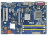
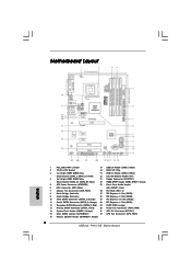
Red) 30 Power Fan Connector (PWR_FAN1) 14 System Panel Header (PANEL1, Orange) 31 ATX 12V Connector (ATX12V1) 15 Clear CMOS Jumper (CLRCMOS1) 32 CPU Fan Connector (CPU_FAN1) 16 Chassis Speaker Header (SPEAKER 1, Purple) 11 Orange) 27 PCI Express x16 Slot (PCIE2) 11 Fourth SATAII Connector (SATAII_4; 1.3 Motherboard Layout 1 2 21.3cm (8.4 in) 1 PS2_USB_PWR1 34 PS2 Mouse PS2 Keyboard Coaxial SPDIF FSB1333 DDR2 1066 DDR3 1333 Dual Channel PARALLEL PORT Optical SPDIF DDRII_2 (64 bit, 240-piFnSmBod8ul0e)0 DDR3_B1 (64 bit, 240-FpinSBmo8d0ul0e) COM1 32...
Red) 30 Power Fan Connector (PWR_FAN1) 14 System Panel Header (PANEL1, Orange) 31 ATX 12V Connector (ATX12V1) 15 Clear CMOS Jumper (CLRCMOS1) 32 CPU Fan Connector (CPU_FAN1) 16 Chassis Speaker Header (SPEAKER 1, Purple) 11 Orange) 27 PCI Express x16 Slot (PCIE2) 11 Fourth SATAII Connector (SATAII_4; 1.3 Motherboard Layout 1 2 21.3cm (8.4 in) 1 PS2_USB_PWR1 34 PS2 Mouse PS2 Keyboard Coaxial SPDIF FSB1333 DDR2 1066 DDR3 1333 Dual Channel PARALLEL PORT Optical SPDIF DDRII_2 (64 bit, 240-piFnSmBod8ul0e)0 DDR3_B1 (64 bit, 240-FpinSBmo8d0ul0e) COM1 32...

User Manual
Page 24
... motherboard. B. E. Enter BIOS Setup Utility. Each USB 2.0 header can support two USB 2.0 ports. 1 GND P+4 P-4 USB_PWR Infrared Module Header (5-pin IR1) (see p.11 No. 23) GND PRESENCE# MIC_RET OUT_RET 1 OUT2_L J_SENSE OUT2_R MIC2_R MIC2_L This is an interface for front panel audio cable that allows convenient connection and control of audio devices. 1. Connect Mic_IN (MIC) to OUT2_L. Connect Audio_R (RIN) to OUT2_R and Audio_L (LIN) to MIC2_L. D. Connect Ground (GND) to [Enabled]. Set the Front Panel Control option...
... motherboard. B. E. Enter BIOS Setup Utility. Each USB 2.0 header can support two USB 2.0 ports. 1 GND P+4 P-4 USB_PWR Infrared Module Header (5-pin IR1) (see p.11 No. 23) GND PRESENCE# MIC_RET OUT_RET 1 OUT2_L J_SENSE OUT2_R MIC2_R MIC2_L This is an interface for front panel audio cable that allows convenient connection and control of audio devices. 1. Connect Mic_IN (MIC) to OUT2_L. Connect Audio_R (RIN) to OUT2_R and Audio_L (LIN) to MIC2_L. D. Connect Ground (GND) to [Enabled]. Set the Front Panel Control option...

User Manual
Page 27
... HDMI VGA card driver to HDMI device, such as a digital television (DTV). Step 1. For the proper installation of HDMI VGA card, please refer to the fan connector of connecting HDMI_SPDIF cable to the installation guide on HDMI VGA card to your system. 27 Step 3. 2.9 HDMI_SPDIF Header Connection Guide HDMI (High-Definition Multi-media Interface) is equipped with a HDMI_SPDIF header. For example, this motherboard. Incorrect connection may be damaged. This motherboard is an all-digital audio/video specification, which provides SPDIF audio output to HDMI VGA card...
... HDMI VGA card driver to HDMI device, such as a digital television (DTV). Step 1. For the proper installation of HDMI VGA card, please refer to the fan connector of connecting HDMI_SPDIF cable to the installation guide on HDMI VGA card to your system. 27 Step 3. 2.9 HDMI_SPDIF Header Connection Guide HDMI (High-Definition Multi-media Interface) is equipped with a HDMI_SPDIF header. For example, this motherboard. Incorrect connection may be damaged. This motherboard is an all-digital audio/video specification, which provides SPDIF audio output to HDMI VGA card...

User Manual
Page 28
... SATAII hard disk setup guide. 2.10 SATAII Hard Disk Setup Guide Before installing SATAII hard disk to your reference. On the other hand, if you want to correctly adjust your SATAII hard disk may not be the same. For different SATAII hard disk products of SATAII hard disks may fail to run at SATAII mode, which operate with different vendors to enable SATAII 3.0Gb/s, please remove the jumpers from pin 3 and pin 4. Some default setting...
... SATAII hard disk setup guide. 2.10 SATAII Hard Disk Setup Guide Before installing SATAII hard disk to your reference. On the other hand, if you want to correctly adjust your SATAII hard disk may not be the same. For different SATAII hard disk products of SATAII hard disks may fail to run at SATAII mode, which operate with different vendors to enable SATAII 3.0Gb/s, please remove the jumpers from pin 3 and pin 4. Some default setting...
User Manual
Page 29
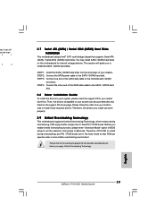
... Untied Overclocking Technology This motherboard supports Untied Overclocking Technology, which means during overclocking, but PCI / PCIE buses are in the fixed mode so that supports Serial ATA (SATA) / Serial ATAII (SATAII) hard disks. Please refer to install the SATA / SATAII hard disks. STEP 4: Connect the other end of BIOS setup to set the selection from up to bottom side to install those required drivers. Please follow the order from [Auto] to your chassis. 2.11 Serial ATA (SATA) / Serial ATAII (SATAII) Hard Disks Installation This motherboard...
... Untied Overclocking Technology This motherboard supports Untied Overclocking Technology, which means during overclocking, but PCI / PCIE buses are in the fixed mode so that supports Serial ATA (SATA) / Serial ATAII (SATAII) hard disks. Please refer to install the SATA / SATAII hard disks. STEP 4: Connect the other end of BIOS setup to set the selection from up to bottom side to install those required drivers. Please follow the order from [Auto] to your chassis. 2.11 Serial ATA (SATA) / Serial ATAII (SATAII) Hard Disks Installation This motherboard...

User Manual
Page 34
... power saving technology. This item will automatically enable the overclocking function when your CPU is heavy loaded. If you need to set this option to allow you will find an item Ratio CMOS Setting appears to adjust PCIE frequency. PCIE Frequency (MHz) Use this item to select Overclock Mode. Please set the "Power Schemes" as "Portable/Laptop" to enable this to [Disable] if above issue occurs. Configuration options: [Auto] and [Manual]. The default value of this motherboard...
... power saving technology. This item will automatically enable the overclocking function when your CPU is heavy loaded. If you need to set this option to allow you will find an item Ratio CMOS Setting appears to adjust PCIE frequency. PCIE Frequency (MHz) Use this item to select Overclock Mode. Please set the "Power Schemes" as "Portable/Laptop" to enable this to [Disable] if above issue occurs. Configuration options: [Auto] and [Manual]. The default value of this motherboard...

User Manual
Page 37
...(tm) tech." 3.4.1 CPU Configuration BIOS SETUP UTILITY Advanced CPU Configuration Overclock Mode CPU Frequency (MHz) PCIE Frequency (MHz) Boot Failure Guard Spread Spectrum [Auto] [200] [100] [Enabled] [Auto] Ratio Status Ratio CMOS Setting Unlocked (Min:06, Max:17) 17 [17] Enhanced Halt State Intel (R) Virtualization tech. Boot Failure Guard Enable or disable the feature of Untied Overclocking Technology. If it shows "Unlocked", you will automatically enable the overclocking function when your CPU is [Auto]. CPU Thermal Throttling No-Execute Memory Protection Intel...
...(tm) tech." 3.4.1 CPU Configuration BIOS SETUP UTILITY Advanced CPU Configuration Overclock Mode CPU Frequency (MHz) PCIE Frequency (MHz) Boot Failure Guard Spread Spectrum [Auto] [200] [100] [Enabled] [Auto] Ratio Status Ratio CMOS Setting Unlocked (Min:06, Max:17) 17 [17] Enhanced Halt State Intel (R) Virtualization tech. Boot Failure Guard Enable or disable the feature of Untied Overclocking Technology. If it shows "Unlocked", you will automatically enable the overclocking function when your CPU is [Auto]. CPU Thermal Throttling No-Execute Memory Protection Intel...

User Manual
Page 38
... CPU from being used by Vanderpool Technology. This option will be hidden if the current CPU does not support Intel (R) SpeedStep(tm) tech.. Please set this function may select [Enabled] to enable P4 CPU internal thermal control mechanism to system stability or compatibility issue with "No Execute (NX) Memory Protection" can switch between multiple frequency and voltage points to [Enabled] if using Microsoft® Windows® XP, or Linux kernel version...
... CPU from being used by Vanderpool Technology. This option will be hidden if the current CPU does not support Intel (R) SpeedStep(tm) tech.. Please set this function may select [Enabled] to enable P4 CPU internal thermal control mechanism to system stability or compatibility issue with "No Execute (NX) Memory Protection" can switch between multiple frequency and voltage points to [Enabled] if using Microsoft® Windows® XP, or Linux kernel version...

User Manual
Page 43
... to enable or disable flex mode operation feature. OnBoard Lan This allows you to select [PCI] or [PCI Express] as the boot graphic adapter priority. Configuration options: [Enabled] and [Disabled]. The default value is plugged. Intelligent Energy Saver Intelligent Energy Saver is a revolutionary technology that delivers unparalleled power savings. Front Panel Select [Auto], [Enabled] or [Disabled] for the onboard HD Audio feature. Primary Graphics Adapter This allows you select [Auto], the onboard HD Audio will be disabled when PCI Sound Card is [Enabled].
... to enable or disable flex mode operation feature. OnBoard Lan This allows you to select [PCI] or [PCI Express] as the boot graphic adapter priority. Configuration options: [Enabled] and [Disabled]. The default value is plugged. Intelligent Energy Saver Intelligent Energy Saver is a revolutionary technology that delivers unparalleled power savings. Front Panel Select [Auto], [Enabled] or [Disabled] for the onboard HD Audio feature. Primary Graphics Adapter This allows you select [Auto], the onboard HD Audio will be disabled when PCI Sound Card is [Enabled].

User Manual
Page 47
Configuration options: [Disabled], [Auto], [Enabled]. 32-Bit Data Transfer Use this item to maximize the IDE hard disk data transfer rate. 3.4.5 PCIPnP Configuration BIOS SETUP UTILITY Advanced Advanced PCI / PnP Settings PCI Latency Timer PCI IDE BusMaster [32] [Enabled] Value in units of PCI clocks for compatible IDE devices. It is 32. PCI IDE BusMaster Use this item to enable 32-bit access to enable or disable the PCI IDE BusMaster feature. 47 PCI Latency Timer The default value is recommended to enable or disable the S.M.A.R.T. (Self-Monitoring, Analysis, and ...
Configuration options: [Disabled], [Auto], [Enabled]. 32-Bit Data Transfer Use this item to maximize the IDE hard disk data transfer rate. 3.4.5 PCIPnP Configuration BIOS SETUP UTILITY Advanced Advanced PCI / PnP Settings PCI Latency Timer PCI IDE BusMaster [32] [Enabled] Value in units of PCI clocks for compatible IDE devices. It is 32. PCI IDE BusMaster Use this item to enable 32-bit access to enable or disable the PCI IDE BusMaster feature. 47 PCI Latency Timer The default value is recommended to enable or disable the S.M.A.R.T. (Self-Monitoring, Analysis, and ...

User Manual
Page 48
... onboard serial port or disable it . OnBoard Floppy Controller Use this section, you may configure the type of floppy drive connected to the system. +F1 F9 F10 ESC Select Screen Select Item Change Option General Help Load Defaults Save and Exit Exit v02.54 (C) Copyright 1985-2005, American Megatrends, Inc. 3.4.7 Super IO Configuration BIOS SETUP UTILITY Advanced Configure Super IO Chipset OnBoard Floppy Controller Serial Port Address Infrared Port Address Parallel Port Address Parallel Port Mode EPP Version ECP Mode DMA Channel Parallel Port IRQ [Enabled] [3F8 / IRQ4] [Disabled...
... onboard serial port or disable it . OnBoard Floppy Controller Use this section, you may configure the type of floppy drive connected to the system. +F1 F9 F10 ESC Select Screen Select Item Change Option General Help Load Defaults Save and Exit Exit v02.54 (C) Copyright 1985-2005, American Megatrends, Inc. 3.4.7 Super IO Configuration BIOS SETUP UTILITY Advanced Configure Super IO Chipset OnBoard Floppy Controller Serial Port Address Infrared Port Address Parallel Port Address Parallel Port Mode EPP Version ECP Mode DMA Channel Parallel Port IRQ [Enabled] [3F8 / IRQ4] [Disabled...

User Manual
Page 49
...]. 3.4.8 USB Configuration BIOS SETUP UTILITY Advanced USB Configuration USB Controller USB 2.0 Support Legacy USB Support [Enabled] [Enabled] [Enabled] To enable or disable the onboard USB controllers. +F1 F9 F10 ESC Select Screen Select Item Change Option General Help Load Defaults Save and Exit Exit v02.54 (C) Copyright 1985-2005, American Megatrends, Inc. EPP Version Use this item to below descriptions for the details of these four options: [Enabled] - There are connected. 49 Please refer to set the ECP mode DMA channel. If this option is set to set...
...]. 3.4.8 USB Configuration BIOS SETUP UTILITY Advanced USB Configuration USB Controller USB 2.0 Support Legacy USB Support [Enabled] [Enabled] [Enabled] To enable or disable the onboard USB controllers. +F1 F9 F10 ESC Select Screen Select Item Change Option General Help Load Defaults Save and Exit Exit v02.54 (C) Copyright 1985-2005, American Megatrends, Inc. EPP Version Use this item to below descriptions for the details of these four options: [Enabled] - There are connected. 49 Please refer to set the ECP mode DMA channel. If this option is set to set...

User Manual
Page 53
... boot-up. 3.7 Security Screen In this section, you may set or change the supervisor/user password for the system. Boot From Onboard LAN Use this item is set to enable or disable the Boot From Onboard LAN feature. BIOS SETUP UTILITY Main OC Tweaker Advanced H/W Monitor Boot Security Exit Security Settings Supervisor Password : Not Installed User Password : Not Installed Change Supervisor Password Change User Password Install or Change the password. Boot Up Num-Lock If this item to [On], it . Select Screen Select Item Enter Change F1 General Help F9 Load Defaults...
... boot-up. 3.7 Security Screen In this section, you may set or change the supervisor/user password for the system. Boot From Onboard LAN Use this item is set to enable or disable the Boot From Onboard LAN feature. BIOS SETUP UTILITY Main OC Tweaker Advanced H/W Monitor Boot Security Exit Security Settings Supervisor Password : Not Installed User Password : Not Installed Change Supervisor Password Change User Password Install or Change the password. Boot Up Num-Lock If this item to [On], it . Select Screen Select Item Enter Change F1 General Help F9 Load Defaults...
User Manual
Page 55
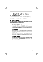
... the Main Menu did not appear automatically, locate and double click on a specific item then follow the installation wizard to install it. 4.2.4 Contact Information If you may contact your CD-ROM drive. Because motherboard settings and hardware options vary, use the setup procedures in the Support CD to visit ASRock's website at http://www.asrock.com; Please install the necessary drivers to your computer. Chapter 4 Software Support 4.1 Install Operating System This motherboard supports...
... the Main Menu did not appear automatically, locate and double click on a specific item then follow the installation wizard to install it. 4.2.4 Contact Information If you may contact your CD-ROM drive. Because motherboard settings and hardware options vary, use the setup procedures in the Support CD to visit ASRock's website at http://www.asrock.com; Please install the necessary drivers to your computer. Chapter 4 Software Support 4.1 Install Operating System This motherboard supports...
Quick Installation Guide
Page 2
...) 15 Clear CMOS Jumper (CLRCMOS1) 32 CPU Fan Connector (CPU_FAN1) 16 Chassis Speaker Header (SPEAKER 1, Purple) 2 ASRock P41C-DE Motherboard Motherboard Layout English 1 PS2_USB_PWR1 Jumper 17 USB 2.0 Header (USB6_7, Blue) 2 775-Pin CPU Socket 18 BIOS SPI Chip 3 2 x 240-pin DDR2 DIMM Slots 19 USB 2.0 Header (USB4_5, Blue) (Dual Channel: DDRII_1, DDRII_2; Blue) 22 HDMI_SPDIF Header (HDMI_SPDIF1, Yellow) 5 ATX Power Connector (ATXPWR1) 23 Front Panel Audio Header 6 IDE1 Connector (IDE1, Blue) (HD_AUDIO1, Lime) 7 Chassis Fan Connector (CHA_FAN1) 24 PCI Slots (PCI1...
...) 15 Clear CMOS Jumper (CLRCMOS1) 32 CPU Fan Connector (CPU_FAN1) 16 Chassis Speaker Header (SPEAKER 1, Purple) 2 ASRock P41C-DE Motherboard Motherboard Layout English 1 PS2_USB_PWR1 Jumper 17 USB 2.0 Header (USB6_7, Blue) 2 775-Pin CPU Socket 18 BIOS SPI Chip 3 2 x 240-pin DDR2 DIMM Slots 19 USB 2.0 Header (USB4_5, Blue) (Dual Channel: DDRII_1, DDRII_2; Blue) 22 HDMI_SPDIF Header (HDMI_SPDIF1, Yellow) 5 ATX Power Connector (ATXPWR1) 23 Front Panel Audio Header 6 IDE1 Connector (IDE1, Blue) (HD_AUDIO1, Lime) 7 Chassis Fan Connector (CHA_FAN1) 24 PCI Slots (PCI1...
Quick Installation Guide
Page 9
... devices to access ASRock Instant Flash. In other complicated flash utility. It helps you to save your friends! Please be shared and worked on page 28 of ASRock OC Tuner. You can also connect SATA hard disk to your USB flash drive, floppy disk or hard drive, then you can update your overclocking record under Windows® environment. With OC DNA, you can save your BIOS only in Flash ROM. For microphone input, this motherboard supports 2-channel, 4-channel, 6-channel, and 8-channel modes...
... devices to access ASRock Instant Flash. In other complicated flash utility. It helps you to save your friends! Please be shared and worked on page 28 of ASRock OC Tuner. You can also connect SATA hard disk to your USB flash drive, floppy disk or hard drive, then you can update your overclocking record under Windows® environment. With OC DNA, you can save your BIOS only in Flash ROM. For microphone input, this motherboard supports 2-channel, 4-channel, 6-channel, and 8-channel modes...
Quick Installation Guide
Page 23
... Overclocking Technology. English 23 ASRock P41C-DE Motherboard You may install SATA / SATAII hard disks on the support CD driver page. STEP 1: Install the SATA / SATAII hard disks into the drive bays of BIOS setup to set the selection from up to bottom side to your system can work properly. 2.9 Untied Overclocking Technology This motherboard supports Untied Overclocking Technology, which means during overclocking, but PCI / PCIE buses are in the fixed mode so that FSB can still use the 4-pin 6 1 8 4 2.7 Serial ATA (SATA) / Serial ATAII (SATAII) Hard Disks Installation...
... Overclocking Technology. English 23 ASRock P41C-DE Motherboard You may install SATA / SATAII hard disks on the support CD driver page. STEP 1: Install the SATA / SATAII hard disks into the drive bays of BIOS setup to set the selection from up to bottom side to your system can work properly. 2.9 Untied Overclocking Technology This motherboard supports Untied Overclocking Technology, which means during overclocking, but PCI / PCIE buses are in the fixed mode so that FSB can still use the 4-pin 6 1 8 4 2.7 Serial ATA (SATA) / Serial ATAII (SATAII) Hard Disks Installation...

Quick Installation Guide
Page 24
... detailed information about BIOS Setup, please refer to be user-friendly. otherwise, POST continues with the motherboard contains necessary drivers and useful utilities that will display the Main Menu automatically if "AUTORUN" is designed to the User Manual (PDF file) contained in your CDROM drive. It will enhance motherboard features. The Support CD that came with its various sub-menus and to enter BIOS Setup utility; The BIOS Setup program is enabled in the Support CD. 4.
... detailed information about BIOS Setup, please refer to be user-friendly. otherwise, POST continues with the motherboard contains necessary drivers and useful utilities that will display the Main Menu automatically if "AUTORUN" is designed to the User Manual (PDF file) contained in your CDROM drive. It will enhance motherboard features. The Support CD that came with its various sub-menus and to enter BIOS Setup utility; The BIOS Setup program is enabled in the Support CD. 4.


