
User Manual
Page 3
... Guide 28 2.11 Serial ATA (SATA) / Serial ATAII (SATAII) Hard Disks Installation 29 2.12 Driver Installation Guide 29 2.13 Untied Overclocking Technology 29 3 BIOS SETUP UTILITY 30 3.1 Introduction 30 3.1.1 BIOS Menu Bar 30 3.1.2 Navigation Keys 31 3.2 Main Screen 31 3.3 OC Tweaker Screen 32 3.4 Advanced Screen 35 3.4.1 CPU Configuration 36 3.4.2 Chipset Configuration 38...
... Guide 28 2.11 Serial ATA (SATA) / Serial ATAII (SATAII) Hard Disks Installation 29 2.12 Driver Installation Guide 29 2.13 Untied Overclocking Technology 29 3 BIOS SETUP UTILITY 30 3.1 Introduction 30 3.1.1 BIOS Menu Bar 30 3.1.2 Navigation Keys 31 3.2 Main Screen 31 3.3 OC Tweaker Screen 32 3.4 Advanced Screen 35 3.4.1 CPU Configuration 36 3.4.2 Chipset Configuration 38...
User Manual
Page 5
... to ASRock's commitment to the hardware installation. In this manual, chapter 1 and 2 contain introduction of this motherboard, please visit our website for specific information about the model you for purchasing ASRock P41C-DE motherboard, a reliable motherboard produced under ASRock's consistently stringent quality control. Because the motherboard specifications and the BIOS software might be available on ASRock website...
... to ASRock's commitment to the hardware installation. In this manual, chapter 1 and 2 contain introduction of this motherboard, please visit our website for specific information about the model you for purchasing ASRock P41C-DE motherboard, a reliable motherboard produced under ASRock's consistently stringent quality control. Because the motherboard specifications and the BIOS software might be available on ASRock website...

User Manual
Page 7
... 13) - AMBIOS 2.3.1 Support - O. Voltage Monitoring: +12V, +5V, +3.3V, Vcore - CPU, VCCM, NB, SB,VTT, GTLRef Voltage Multi-adjustment - ASRock OC DNA (see CAUTION 9) - 8Mb AMI BIOS - AMI Legal BIOS - Drivers, Utilities, AntiVirus Software (Trial Version), ASRock Software Suite (CyberLink DVD Suite and Creative Sound Blaster X-Fi MB) (OEM and Trial Version) - Intelligent Energy Saver...
... 13) - AMBIOS 2.3.1 Support - O. Voltage Monitoring: +12V, +5V, +3.3V, Vcore - CPU, VCCM, NB, SB,VTT, GTLRef Voltage Multi-adjustment - ASRock OC DNA (see CAUTION 9) - 8Mb AMI BIOS - AMI Legal BIOS - Drivers, Utilities, AntiVirus Software (Trial Version), ASRock Software Suite (CyberLink DVD Suite and Creative Sound Blaster X-Fi MB) (OEM and Trial Version) - Intelligent Energy Saver...

User Manual
Page 8
... Ready (EuP ready power supply is required) (see CAUTION 16) * For detailed product information, please visit our website: http://www.asrock.com WARNING Please realize that there is a certain risk involved with 64-bit CPU, there is no such limitation. 8 Overclocking may be...4GB for the reservation for proper installation. 5. - About the setting of memory modules on this motherboard, it will operate in the BIOS, applying Untied Overclocking Technology, or using the thirdparty overclocking tools. Please read the installation guide of "Hyper Threading Technology", please check page...
... Ready (EuP ready power supply is required) (see CAUTION 16) * For detailed product information, please visit our website: http://www.asrock.com WARNING Please realize that there is a certain risk involved with 64-bit CPU, there is no such limitation. 8 Overclocking may be...4GB for the reservation for proper installation. 5. - About the setting of memory modules on this motherboard, it will operate in the BIOS, applying Untied Overclocking Technology, or using the thirdparty overclocking tools. Please read the installation guide of "Hyper Threading Technology", please check page...

User Manual
Page 9
... ASRock website: http://www.asrock.com 12. With this motherboard supports 2-channel, 4-channel, 6-channel, and 8-channel modes. OC DNA, an exclusive utility developed by hardware monitor function and overclock your friends! The software name itself - With OC DNA, you can save your BIOS ... an additional floppy diskette or other than the recommended CPU bus frequencies may cause the instability of Intelligent Energy Saver. ASRock Instant Flash is capable of overclocking settings. Just launch this motherboard supports both stereo and mono modes. Your friends then...
... ASRock website: http://www.asrock.com 12. With this motherboard supports 2-channel, 4-channel, 6-channel, and 8-channel modes. OC DNA, an exclusive utility developed by hardware monitor function and overclock your friends! The software name itself - With OC DNA, you can save your BIOS ... an additional floppy diskette or other than the recommended CPU bus frequencies may cause the instability of Intelligent Energy Saver. ASRock Instant Flash is capable of overclocking settings. Just launch this motherboard supports both stereo and mono modes. Your friends then...

User Manual
Page 11
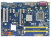
...1 FSB2 1 FSB3 Intel G41 Chipset PCIE1 EuP Ready LAN PCIE2 PHY RoHS P41C-DE IDE1 CHA_FAN1 SATAII_4 SATAII_2 Super IO PCIE3 PCIE4 Intel ICH7 SATAII_3 AUDIO CODEC HD_AUDIO1 1 HDMI_SPDIF1 1 FLOPPY1 PCI1 PCI2 1 IR1 8Mb BIOS CMOS Battery USB4_5 1 USB6_7 1 SPEAKER1 CLRCMOS1 PLED PWRBTN 1 1 1 HDLED ... (12.0 in) 5 6 7 8 9 10 11 12 13 14 1 PS2_USB_PWR1 Jumper 17 USB 2.0 Header (USB6_7, Blue) 2 775-Pin CPU Socket 18 BIOS SPI Chip 3 2 x 240-pin DDR2 DIMM Slots 19 USB 2.0 Header (USB4_5, Blue) (Dual Channel: DDRII_1, DDRII_2; Orange) 27 PCI Express x16 Slot ...
...1 FSB2 1 FSB3 Intel G41 Chipset PCIE1 EuP Ready LAN PCIE2 PHY RoHS P41C-DE IDE1 CHA_FAN1 SATAII_4 SATAII_2 Super IO PCIE3 PCIE4 Intel ICH7 SATAII_3 AUDIO CODEC HD_AUDIO1 1 HDMI_SPDIF1 1 FLOPPY1 PCI1 PCI2 1 IR1 8Mb BIOS CMOS Battery USB4_5 1 USB6_7 1 SPEAKER1 CLRCMOS1 PLED PWRBTN 1 1 1 HDLED ... (12.0 in) 5 6 7 8 9 10 11 12 13 14 1 PS2_USB_PWR1 Jumper 17 USB 2.0 Header (USB6_7, Blue) 2 775-Pin CPU Socket 18 BIOS SPI Chip 3 2 x 240-pin DDR2 DIMM Slots 19 USB 2.0 Header (USB4_5, Blue) (Dual Channel: DDRII_1, DDRII_2; Orange) 27 PCI Express x16 Slot ...

User Manual
Page 21
To clear and reset the system parameters to clear the CMOS when you just finish updating the BIOS, you must boot up events. The illustration shows a 3-pin jumper whose pin1 and pin2 are setup. However, please do the clear-CMOS action. 21 If ... power cord from the power supply. Jumper Setting Description PS2_USB_PWR1 (see p.11, No. 15) 1_2 2_3 Default Clear CMOS Note: CLRCMOS1 allows you update the BIOS. After waiting for 15 seconds, use a jumper cap to enable +5VSB (standby) for 5 seconds. The data in CMOS. Clear CMOS Jumper (CLRCMOS1) (see p.11 No...
To clear and reset the system parameters to clear the CMOS when you just finish updating the BIOS, you must boot up events. The illustration shows a 3-pin jumper whose pin1 and pin2 are setup. However, please do the clear-CMOS action. 21 If ... power cord from the power supply. Jumper Setting Description PS2_USB_PWR1 (see p.11, No. 15) 1_2 2_3 Default Clear CMOS Note: CLRCMOS1 allows you update the BIOS. After waiting for 15 seconds, use a jumper cap to enable +5VSB (standby) for 5 seconds. The data in CMOS. Clear CMOS Jumper (CLRCMOS1) (see p.11 No...

User Manual
Page 22
...: 2-3 DDR3 1333 / DDR2 1066 FSB1333 FSB2 FSB3 FSB2: 4-5 FSB3: 1-2 Overclocking Setting: When you mount a FSB800 or FSB1066 CPU, and try to overclock to FSB1333 (by BIOS setting) you may not work properly on this motherboard, you need to adjust the jumpers. Please refer to adjust the jumpers. Otherwise, the CPU and...
...: 2-3 DDR3 1333 / DDR2 1066 FSB1333 FSB2 FSB3 FSB2: 4-5 FSB3: 1-2 Overclocking Setting: When you mount a FSB800 or FSB1066 CPU, and try to overclock to FSB1333 (by BIOS setting) you may not work properly on this motherboard, you need to adjust the jumpers. Please refer to adjust the jumpers. Otherwise, the CPU and...

User Manual
Page 24
... IRRX This header supports an optional wireless transmitting and receiving infrared module. E. Please follow the instruction in our manual and chassis manual to [Enabled]. B. Enter BIOS Setup Utility. Set the Front Panel Control option from [Auto] to install your system. 2.
... IRRX This header supports an optional wireless transmitting and receiving infrared module. E. Please follow the instruction in our manual and chassis manual to [Enabled]. B. Enter BIOS Setup Utility. Set the Front Panel Control option from [Auto] to install your system. 2.
User Manual
Page 29
... to [Manual]. Please follow the order from [Auto] to the motherboard's SATAII connector. STEP 1: Install the SATA / SATAII hard disks into the drive bays of BIOS setup to set the selection from up to bottom side to the SATA / SATAII hard disk. 2.11 Serial ATA (SATA) / Serial ATAII (SATAII) Hard Disks...
... to [Manual]. Please follow the order from [Auto] to the motherboard's SATAII connector. STEP 1: Install the SATA / SATAII hard disks into the drive bays of BIOS setup to set the selection from up to bottom side to the SATA / SATAII hard disk. 2.11 Serial ATA (SATA) / Serial ATAII (SATAII) Hard Disks...

User Manual
Page 30
..., the following selections: Main To set up the system time/date information OC Tweaker To set up overclocking features Advanced To set up the advanced BIOS features H/W Monitor To display current hardware status Boot To set up the default system device to locate and load the Operating System Security To set... Bar The top of the screen has a menu bar with its test routines. The SPI Memory on . You may run the BIOS SETUP UTILITY when you wish to enter the BIOS SETUP UTILITY after POST, restart the system by pressing + + , or by turning the system off and then back on the ...
..., the following selections: Main To set up the system time/date information OC Tweaker To set up overclocking features Advanced To set up the advanced BIOS features H/W Monitor To display current hardware status Boot To set up the default system device to locate and load the Operating System Security To set... Bar The top of the screen has a menu bar with its test routines. The SPI Memory on . You may run the BIOS SETUP UTILITY when you wish to enter the BIOS SETUP UTILITY after POST, restart the system by pressing + + , or by turning the system off and then back on the ...

User Manual
Page 31
...] Use this item to specify the system time. 3.1.2Navigation Keys Please check the following table for all the settings To save changes and exit the BIOS SETUP UTILITY To jump to the Exit Screen or exit the current screen 3.2 Main Screen When you enter the... UTILITY Main OC Tweaker Advanced H/W Monitor Boot Security Exit System Overview System Time System Date [14:00:09] [Fri 10/23/2009] BIOS Version : P41C-DE P1.00 Processor Type : Intel (R) Core (TM) 2 Duo CPU E6850 @ 3.00GHz (64bit) Processor Speed : 3148MHz Microcode Update : 6FB/B6 Cache Size : 1024KB Total Memory DDRII1 ...
...] Use this item to specify the system time. 3.1.2Navigation Keys Please check the following table for all the settings To save changes and exit the BIOS SETUP UTILITY To jump to the Exit Screen or exit the current screen 3.2 Main Screen When you enter the... UTILITY Main OC Tweaker Advanced H/W Monitor Boot Security Exit System Overview System Time System Date [14:00:09] [Fri 10/23/2009] BIOS Version : P41C-DE P1.00 Processor Type : Intel (R) Core (TM) 2 Duo CPU E6850 @ 3.00GHz (64bit) Processor Speed : 3148MHz Microcode Update : 6FB/B6 Cache Size : 1024KB Total Memory DDRII1 ...

User Manual
Page 32
...], [CPU 2.88GHz], [CPU 3.00GHz], [CPU 3.12GHz] and [CPU 3.27GHz]. It should be done at your own risk and expense. DRAM Command Rate Use this motherboard. BIOS SETUP UTILITY Main OC Tweaker Advanced H/W Monitor Boot Security Exit OC Tweaker Settings Load CPU EZ OC Setting [Press Enter] DRAM Frequency DRAM Command Rate...
...], [CPU 2.88GHz], [CPU 3.00GHz], [CPU 3.12GHz] and [CPU 3.27GHz]. It should be done at your own risk and expense. DRAM Command Rate Use this motherboard. BIOS SETUP UTILITY Main OC Tweaker Advanced H/W Monitor Boot Security Exit OC Tweaker Settings Load CPU EZ OC Setting [Press Enter] DRAM Frequency DRAM Command Rate...

User Manual
Page 33
... DRAM clocks for TWR. Max: 15. Max: 10. DRAM tWR This controls the number of DRAM clocks for TCL. Max: 13. Min: 2. DRAM Timing Configuration BIOS SETUP UTILITY OC Tweaker DRAM Timing Control DRAM tCL 6 DRAM tRCD 6 DRAM tRP 6 DRAM tRAS 15 DRAM tRFC 44 DRAM tWR 6 DRAM tWTR 4 DRAM tRRD...
... DRAM clocks for TWR. Max: 15. Max: 10. DRAM tWR This controls the number of DRAM clocks for TCL. Max: 13. Min: 2. DRAM Timing Configuration BIOS SETUP UTILITY OC Tweaker DRAM Timing Control DRAM tCL 6 DRAM tRCD 6 DRAM tRP 6 DRAM tRAS 15 DRAM tRFC 44 DRAM tWR 6 DRAM tWTR 4 DRAM tRRD...

User Manual
Page 36
CPU Configuration Chipset Configuration ACPI Configuration Storage Configuration PCIPnP Configuration Floppy Configuration SuperIO Configuration USB Configuration BIOS Update Utility ASRock Instant Flash Select Screen Select Item Enter Go to malfunction. BIOS SETUP UTILITY Main OC Tweaker Advanced H/W Monitor Boot Security Exit Advanced Settings Options for CPU WARNING : Setting wrong values in this section, you...
CPU Configuration Chipset Configuration ACPI Configuration Storage Configuration PCIPnP Configuration Floppy Configuration SuperIO Configuration USB Configuration BIOS Update Utility ASRock Instant Flash Select Screen Select Item Enter Go to malfunction. BIOS SETUP UTILITY Main OC Tweaker Advanced H/W Monitor Boot Security Exit Advanced Settings Options for CPU WARNING : Setting wrong values in this section, you...

User Manual
Page 37
... this item appear to adjust the ratio value, please disable the option " Intel (R) SpeedStep(tm) tech." The default value is "Locked" or "Unlocked". 3.4.1 CPU Configuration BIOS SETUP UTILITY Advanced CPU Configuration Overclock Mode CPU Frequency (MHz) PCIE Frequency (MHz) Boot Failure Guard Spread Spectrum [Auto] [200] [100] [Enabled] [Auto] Ratio Status...
... this item appear to adjust the ratio value, please disable the option " Intel (R) SpeedStep(tm) tech." The default value is "Locked" or "Unlocked". 3.4.1 CPU Configuration BIOS SETUP UTILITY Advanced CPU Configuration Overclock Mode CPU Frequency (MHz) PCIE Frequency (MHz) Boot Failure Guard Spread Spectrum [Auto] [200] [100] [Enabled] [Auto] Ratio Status...

User Manual
Page 39
3.4.2 Chipset Configuration BIOS SETUP UTILITY Advanced Chipset Settings DRAM RCOMP and tRD Configuration DRAM DLL SKEW Configuration Fixed Mode Operation [Enabled] Intelligent Energy Saver Primary Graphics Adapter Onboard ... 1985-2005, American Megatrends, Inc. DRAM CH0 G1 (Command) This controls the number of DRAM CH0 G0 (Data). Max: 15. DRAM RCOMP and tRD Configuration BIOS SETUP UTILITY Advanced DRAM RCOMP STRENGTH Settings DRAM CH0 RCOMP Settings : 54-0-11-6-6-6-6 DRAM CH0 RCOMP ODT DRAM CH0 G0 (Data) DRAM CH0 G1 (Command...
3.4.2 Chipset Configuration BIOS SETUP UTILITY Advanced Chipset Settings DRAM RCOMP and tRD Configuration DRAM DLL SKEW Configuration Fixed Mode Operation [Enabled] Intelligent Energy Saver Primary Graphics Adapter Onboard ... 1985-2005, American Megatrends, Inc. DRAM CH0 G1 (Command) This controls the number of DRAM CH0 G0 (Data). Max: 15. DRAM RCOMP and tRD Configuration BIOS SETUP UTILITY Advanced DRAM RCOMP STRENGTH Settings DRAM CH0 RCOMP Settings : 54-0-11-6-6-6-6 DRAM CH0 RCOMP ODT DRAM CH0 G0 (Data) DRAM CH0 G1 (Command...

User Manual
Page 41
... value is [Auto]. The default value is [Auto]. DRAM CH1 CLKSET0 SKEW This controls the number of DRAM CH1 CLKSET1 SKEW. DRAM DLL SKEW Configuration BIOS SETUP UTILITY Advanced DRAM DLL SKEW Settings DRAM CH0 CLKSET0 SKEW Info:0-0-0-0-0-0 DRAM CH0 CLKSET0 SKEW [Auto] DRAM CH0 CLKSET1 SKEW Info:0-0-0-0-0-0 DRAM CH0 CLKSET1...
... value is [Auto]. The default value is [Auto]. DRAM CH1 CLKSET0 SKEW This controls the number of DRAM CH1 CLKSET1 SKEW. DRAM DLL SKEW Configuration BIOS SETUP UTILITY Advanced DRAM DLL SKEW Settings DRAM CH0 CLKSET0 SKEW Info:0-0-0-0-0-0 DRAM CH0 CLKSET0 SKEW [Auto] DRAM CH0 CLKSET1 SKEW Info:0-0-0-0-0-0 DRAM CH0 CLKSET1...

User Manual
Page 43
... you can also choose our Intelligent Energy Saver utility to enable this item to [Enabled]. Intelligent Energy Saver Intelligent Energy Saver is [Disabled]. Besides the BIOS option, you to enable or disable the "OnBoard Lan" feature. 43 If you to enable or disable flex mode operation feature. The default value is...
... you can also choose our Intelligent Energy Saver utility to enable this item to [Enabled]. Intelligent Energy Saver Intelligent Energy Saver is [Disabled]. Besides the BIOS option, you to enable or disable the "OnBoard Lan" feature. 43 If you to enable or disable flex mode operation feature. The default value is...

User Manual
Page 44
... mode. RTC Alarm Power On Use this item to enable or disable PS/2 keyboard to auto-detect or disable the Suspend-toRAM feature. 3.4.3 ACPI Configuration BIOS SETUP UTILITY Advanced ACPI Configuration Suspend To RAM Restore on AC/Power Loss Ring-In Power On PCI Devices Power On PS / 2 Keyboard Power On...
... mode. RTC Alarm Power On Use this item to enable or disable PS/2 keyboard to auto-detect or disable the Suspend-toRAM feature. 3.4.3 ACPI Configuration BIOS SETUP UTILITY Advanced ACPI Configuration Suspend To RAM Restore on AC/Power Loss Ring-In Power On PCI Devices Power On PS / 2 Keyboard Power On...


