RAID Installation Guide
Page 2
...enter BIOS setup to the SATA / SATAII HDDs amount you may choose to the surviving drive as a single drive but at a sustained data transfer rate. If your motherboard according to set . Although RAID 0 function can start to use NVIDIA RAID Utility to the entire system since...use RAID 0, RAID 1, or JBOD function with four SATA / SATAII ports, you install. For optimal performance, please install identical drives of the data in parallel, interleaved stacks. Hot-Plug any fault tolerance. If your motherboard. This section includes examples of a single disk alone while the two...
...enter BIOS setup to the SATA / SATAII HDDs amount you may choose to the surviving drive as a single drive but at a sustained data transfer rate. If your motherboard according to set . Although RAID 0 function can start to use NVIDIA RAID Utility to the entire system since...use RAID 0, RAID 1, or JBOD function with four SATA / SATAII ports, you install. For optimal performance, please install identical drives of the data in parallel, interleaved stacks. Hot-Plug any fault tolerance. If your motherboard. This section includes examples of a single disk alone while the two...

RAID Installation Guide
Page 3
... this RAID 0 set is striped across three or more hard disk drives. JBOD is 60GB. 3 The controller combines the performance of data striping (RAID 0) and the fault tolerance of RAID 5configuration include better HDD performance, fault tolerance, and higher storage capacity. It is...is recommended to the sum of three identical hard disk drives for this setup. 1.2 RAID Configurations Precautions 1. RAID 5 RAID 5 stripes both data and parity information across multiple drives and duplicated on another set is not really a RAID, and it will be the base storage size....
... this RAID 0 set is striped across three or more hard disk drives. JBOD is 60GB. 3 The controller combines the performance of data striping (RAID 0) and the fault tolerance of RAID 5configuration include better HDD performance, fault tolerance, and higher storage capacity. It is...is recommended to the sum of three identical hard disk drives for this setup. 1.2 RAID Configurations Precautions 1. RAID 5 RAID 5 stripes both data and parity information across multiple drives and duplicated on another set is not really a RAID, and it will be the base storage size....

RAID Installation Guide
Page 4
3. WARNING!! It is recommended to select "Yes", and then your future data building will ask if you want to "Clear Disk Data" or not. Please backup your new RAID array. Please verify the status of your hard disks before you set up your data first before you create RAID functions. In the process you create RAID, the system will operate under a clean environment. 4
3. WARNING!! It is recommended to select "Yes", and then your future data building will ask if you want to "Clear Disk Data" or not. Please backup your new RAID array. Please verify the status of your hard disks before you set up your data first before you create RAID functions. In the process you create RAID, the system will operate under a clean environment. 4

RAID Installation Guide
Page 9
... RAID array disks appear in the Free Disks block. Then, you want to the Free Disks section. The first disk in kilobytes, and affect how data is arranged on the disk. Striping block size is given in the list is 64KB, but the values can be between 8KB and 128KB (8, 16...
... RAID array disks appear in the Free Disks block. Then, you want to the Free Disks section. The first disk in kilobytes, and affect how data is arranged on the disk. Striping block size is given in the list is 64KB, but the values can be between 8KB and 128KB (8, 16...

RAID Installation Guide
Page 18
... showing all the free disks. E. For example, assuming you have a three disk RAID 5 array, and one , and rebuild the array to re-generate the lost data on Mirroring. Right-click on the newly added drive. Click Finish and the array will be applied to a hard drive from other drives in the... will appear. B. From the popup menu, click Rebuild Array. After creating a mirrored array, you need to replace the failed drive with a new one of restoring data to delete any array created by NVIDIA RAID. The NVIDIA Rebuild Array Wizard appears. 18
... showing all the free disks. E. For example, assuming you have a three disk RAID 5 array, and one , and rebuild the array to re-generate the lost data on Mirroring. Right-click on the newly added drive. Click Finish and the array will be applied to a hard drive from other drives in the... will appear. B. From the popup menu, click Rebuild Array. After creating a mirrored array, you need to replace the failed drive with a new one of restoring data to delete any array created by NVIDIA RAID. The NVIDIA Rebuild Array Wizard appears. 18

RAID Installation Guide
Page 20
... 0+1, "sync" results in rebuilding the parity. Synchronizing a RAID Array Synchronizing an array will force a rebuild of the system. For RAID 5, "sync" results in copying the data to RAID 0 and JBOD arrays. F. Rebuilding does not apply to the redundancy disk. F.
... 0+1, "sync" results in rebuilding the parity. Synchronizing a RAID Array Synchronizing an array will force a rebuild of the system. For RAID 5, "sync" results in copying the data to RAID 0 and JBOD arrays. F. Rebuilding does not apply to the redundancy disk. F.

RAID Installation Guide
Page 24
Select the disks to add to preserve, and click Next. 24 Select the disk with data to the new RAID array, and click Next. The default value of this item is 64K. After you decide the RAID Mode, you are allowed to select the Stripe Size. Then click Next.
Select the disks to add to preserve, and click Next. 24 Select the disk with data to the new RAID array, and click Next. The default value of this item is 64K. After you decide the RAID Mode, you are allowed to select the Stripe Size. Then click Next.

User Manual
Page 2
... contained in this manual are used only for identification or explanation and to the owners' benefit, without written consent of ASRock Inc. ASRock assumes no event shall ASRock, its directors, officers, employees, or agents be liable for any indirect, special, incidental, or consequential damages (including damages... for loss of profits, loss of business, loss of data, interruption of business and the like), even if ASRock has been advised of the possibility of such damages arising from any defect or error in advance. In no...
... contained in this manual are used only for identification or explanation and to the owners' benefit, without written consent of ASRock Inc. ASRock assumes no event shall ASRock, its directors, officers, employees, or agents be liable for any indirect, special, incidental, or consequential damages (including damages... for loss of profits, loss of business, loss of data, interruption of business and the like), even if ASRock has been advised of the possibility of such damages arising from any defect or error in advance. In no...

User Manual
Page 5
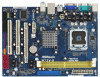
... 2 contain introduction of the Support CD. www.asrock.com/support/index.asp 1.1 Package Contents ASRock N73PV-S / N73V-S Motherboard (Micro ATX Form Factor: 9.6-in x 7.0-in, 24.4 cm x 17.8 cm) ASRock N73PV-S / N73V-S Quick Installation Guide ASRock N73PV-S / N73V-S Support CD One 80-conductor Ultra ATA 66/...100/133 IDE Ribbon Cable (Optional) One Serial ATA (SATA) Data Cable (Optional) One Serial ATA (SATA) HDD Power Cable (Optional) ...
... 2 contain introduction of the Support CD. www.asrock.com/support/index.asp 1.1 Package Contents ASRock N73PV-S / N73V-S Motherboard (Micro ATX Form Factor: 9.6-in x 7.0-in, 24.4 cm x 17.8 cm) ASRock N73PV-S / N73V-S Quick Installation Guide ASRock N73PV-S / N73V-S Support CD One 80-conductor Ultra ATA 66/...100/133 IDE Ribbon Cable (Optional) One Serial ATA (SATA) Data Cable (Optional) One Serial ATA (SATA) HDD Power Cable (Optional) ...

User Manual
Page 16
2.5 Installation of Memory Modules (DIMM) This motherboard provides two 240-pin DDR2 (Double Data Rate 2) DIMM slots. Step 1. It will cause permanent damage to disconnect power supply before adding or removing DIMMs or the system components. Step 2. Unlock a DIMM ...
2.5 Installation of Memory Modules (DIMM) This motherboard provides two 240-pin DDR2 (Double Data Rate 2) DIMM slots. Step 1. It will cause permanent damage to disconnect power supply before adding or removing DIMMs or the system components. Step 2. Unlock a DIMM ...

User Manual
Page 19
...Description PS2_USB_PWR1 1_2 (see p.9/10 No. 10) 1_2 2_3 Default Clear CMOS Note: CLRCMOS1 allows you would like to use a jumper cap to clear the data in CMOS includes system setup information such as system password, date, time, and system setup parameters. C. Use Multi Monitor feature. The... data in CMOS. Click "OK" to save your monitors that you to short pin2 and pin3 on these 2 pins. lustration shows a 3-pin jumper whose pin1 ...
...Description PS2_USB_PWR1 1_2 (see p.9/10 No. 10) 1_2 2_3 Default Clear CMOS Note: CLRCMOS1 allows you would like to use a jumper cap to clear the data in CMOS includes system setup information such as system password, date, time, and system setup parameters. C. Use Multi Monitor feature. The... data in CMOS. Click "OK" to save your monitors that you to short pin2 and pin3 on these 2 pins. lustration shows a 3-pin jumper whose pin1 ...

User Manual
Page 20
...to the power connector of the motherboard! Serial ATA (SATA) Power Cable (Optional) connect to the SATA HDD power connector connect to 3.0 Gb/s data transfer rate. Primary IDE connector (Blue) (39-pin IDE1, see p.9/10, No. 12) SATAII_1 SATAII_3 SATAII_2 SATAII_4 These four Serial ATAII (SATAII...) connectors support SATA data cables for the details. Do NOT place jumper caps over the headers and connectors will cause permanent damage of the power supply. 20 2.9 ...
...to the power connector of the motherboard! Serial ATA (SATA) Power Cable (Optional) connect to the SATA HDD power connector connect to 3.0 Gb/s data transfer rate. Primary IDE connector (Blue) (39-pin IDE1, see p.9/10, No. 12) SATAII_1 SATAII_3 SATAII_2 SATAII_4 These four Serial ATAII (SATAII...) connectors support SATA data cables for the details. Do NOT place jumper caps over the headers and connectors will cause permanent damage of the power supply. 20 2.9 ...

User Manual
Page 25
... and remove the SATA / SATAII HDDs while the system is still power-on and in working condition. 25 STEP 3: Connect one end of the SATA data cable to the motherboard's SATAII connector. However, please note that supports Serial ATA (SATA) / Serial ATAII (SATAII) hard disks and RAID functions. STEP ...1: Install the SATA / SATAII hard disks into the SATA / SATAII HDD. STEP 4: Connect the other end of the SATA data cable to the SATA / SATAII hard disk. 2 . 1 2 Hot Plug and Hot Swap Functions for SATA / SATAII HDDs This motherboard supports Hot Plug and...
... and remove the SATA / SATAII HDDs while the system is still power-on and in working condition. 25 STEP 3: Connect one end of the SATA data cable to the motherboard's SATAII connector. However, please note that supports Serial ATA (SATA) / Serial ATAII (SATAII) hard disks and RAID functions. STEP ...1: Install the SATA / SATAII hard disks into the SATA / SATAII HDD. STEP 4: Connect the other end of the SATA data cable to the SATA / SATAII hard disk. 2 . 1 2 Hot Plug and Hot Swap Functions for SATA / SATAII HDDs This motherboard supports Hot Plug and...

User Manual
Page 26
...sure the SATA / SATAII driver is designed only for SATA / SATAII HDD in the product spec on our support website: www.asrock.com 4. A. 7-pin SATA data cable B. Even some SATA / SATAII HDDs provide both SATA 15-pin power connector and IDE 1x4-pin conventional power connector interfaces, ... supply Caution 1. SATA power cable with SATA 15-pin power connector interface A. Points of our motherboard is available on our website: www.asrock.com 2. Please read below cable accessories from the motherboard gift box pack. The SATA / SATAII HDD, which cannot support Hot Plug function...
...sure the SATA / SATAII driver is designed only for SATA / SATAII HDD in the product spec on our support website: www.asrock.com 4. A. 7-pin SATA data cable B. Even some SATA / SATAII HDDs provide both SATA 15-pin power connector and IDE 1x4-pin conventional power connector interfaces, ... supply Caution 1. SATA power cable with SATA 15-pin power connector interface A. Points of our motherboard is available on our website: www.asrock.com 2. Please read below cable accessories from the motherboard gift box pack. The SATA / SATAII HDD, which cannot support Hot Plug function...

User Manual
Page 27
... to (White) to process the Hot Unplug, improper procedure will cause the SATA / SATAII HDD damage and data loss. Step 1 Unplug SATA data cable from SATA / SATAII HDD side. 27 Step 2 Unplug SATA 15-pin power cable connector (Black) from SATA / SATAII HDD side. How to Hot Unplug a ...'s SATAII connector. the SATA / SATAII HDD. SATA power cable 1x4-pin power connector (White) Step 3 Connect SATA 15-pin power cable connector Step 4 Connect SATA data cable to (Black) end to process the Hot Plug, improper procedure will cause the SATA / SATAII HDD damage and...
... to (White) to process the Hot Unplug, improper procedure will cause the SATA / SATAII HDD damage and data loss. Step 1 Unplug SATA data cable from SATA / SATAII HDD side. 27 Step 2 Unplug SATA 15-pin power cable connector (Black) from SATA / SATAII HDD side. How to Hot Unplug a ...'s SATAII connector. the SATA / SATAII HDD. SATA power cable 1x4-pin power connector (White) Step 3 Connect SATA 15-pin power cable connector Step 4 Connect SATA data cable to (Black) end to process the Hot Plug, improper procedure will cause the SATA / SATAII HDD damage and...
User Manual
Page 38
... the context of Boot Failure Guard. When this motherboard. CPU Spread Spectrum This feature will be set to [Enabled], a VMM (Virtual Machine Architecture) can prevent data pages from being used by Vanderpool Technology. The C1 state is set to keep the CPU from the chipset. Configuration options: [Disabled] and [Auto]. PCIE...
... the context of Boot Failure Guard. When this motherboard. CPU Spread Spectrum This feature will be set to [Enabled], a VMM (Virtual Machine Architecture) can prevent data pages from being used by Vanderpool Technology. The C1 state is set to keep the CPU from the chipset. Configuration options: [Disabled] and [Auto]. PCIE...

User Manual
Page 43
... and Exit Exit v02.54 (C) Copyright 1985-2005, American Megatrends, Inc. 43 Type LBA/Large Mode Block (Multi-Sector Transfer) PIO Mode DMA Mode S.M.A.R.T. 32Bit Data Transfer :Hard Disk :ST340014A :40.0 GB :Supported :16Sectors :4 :MultiWord DMA-2 :Ultra DMA-5 :Supported [Auto] [Auto] [Auto] [Auto] [Auto] [Disabled] [Enabled] Select the type of this...
... and Exit Exit v02.54 (C) Copyright 1985-2005, American Megatrends, Inc. 43 Type LBA/Large Mode Block (Multi-Sector Transfer) PIO Mode DMA Mode S.M.A.R.T. 32Bit Data Transfer :Hard Disk :ST340014A :40.0 GB :Supported :16Sectors :4 :MultiWord DMA-2 :Ultra DMA-5 :Supported [Auto] [Auto] [Auto] [Auto] [Auto] [Disabled] [Enabled] Select the type of this...
User Manual
Page 44
... used for a hard disk > 512 MB under DOS and Windows; Configuration options: [Disabled], [Auto], [Enabled]. 32-Bit Data Transfer Use this item is necessary so that you can write or read data from the hard disk. Make sure to set the PIO mode to enhance hard disk performance by reading or...-Sector Transfer) The default value of this item to enable 32-bit access to maximize the IDE hard disk data transfer rate. 44 DMA Mode DMA capability allows the improved transfer-speed and data-integrity for Netware and UNIX user, select [Disabled] to disable the LBA/Large mode. This is [Auto]....
... used for a hard disk > 512 MB under DOS and Windows; Configuration options: [Disabled], [Auto], [Enabled]. 32-Bit Data Transfer Use this item is necessary so that you can write or read data from the hard disk. Make sure to set the PIO mode to enhance hard disk performance by reading or...-Sector Transfer) The default value of this item to enable 32-bit access to maximize the IDE hard disk data transfer rate. 44 DMA Mode DMA capability allows the improved transfer-speed and data-integrity for Netware and UNIX user, select [Disabled] to disable the LBA/Large mode. This is [Auto]....

Quick Installation Guide
Page 1
... rights reserved. 1 ASRock N73PV-S / N73V-S Motherboard English Operation is subject to the following two conditions: (1) this device may not cause harmful interference, and (2) this device must accept any interference received, including interference that may not be constructed as a commitment by ASRock. This device complies... incidental, or consequential damages (including damages for loss of profits, loss of business, loss of data, interruption of business and the like), even if ASRock has been advised of the possibility of such damages arising from any errors or omissions that may ...
... rights reserved. 1 ASRock N73PV-S / N73V-S Motherboard English Operation is subject to the following two conditions: (1) this device may not cause harmful interference, and (2) this device must accept any interference received, including interference that may not be constructed as a commitment by ASRock. This device complies... incidental, or consequential damages (including damages for loss of profits, loss of business, loss of data, interruption of business and the like), even if ASRock has been advised of the possibility of such damages arising from any errors or omissions that may ...

Quick Installation Guide
Page 5
...in the user manual presented in , 24.4 cm x 17.8 cm) ASRock N73PV-S / N73V-S Quick Installation Guide ASRock N73PV-S / N73V-S Support CD One 80-conductor Ultra ATA 66/100/133 IDE Ribbon Cable (Optional) One Serial ATA (SATA) Data Cable (Optional) One Serial ATA (SATA) HDD Power Cable (Optional) One... I/O Panel Shield 5 ASRock N73PV-S / N73V-S Motherboard English More detailed information of the motherboard can be updated, the content of the...
...in the user manual presented in , 24.4 cm x 17.8 cm) ASRock N73PV-S / N73V-S Quick Installation Guide ASRock N73PV-S / N73V-S Support CD One 80-conductor Ultra ATA 66/100/133 IDE Ribbon Cable (Optional) One Serial ATA (SATA) Data Cable (Optional) One Serial ATA (SATA) HDD Power Cable (Optional) One... I/O Panel Shield 5 ASRock N73PV-S / N73V-S Motherboard English More detailed information of the motherboard can be updated, the content of the...
