User Manual
Page 6
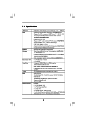
... - 4 x Ready-to 1920x1440 @ 60Hz - 5.1 CH HD Audio (VIA® VT1705 Audio Codec) - Supports PXE I /O - Support for Socket AM3+ processors (see CAUTION 5) - 2 x DDR3 DIMM slots - FSB 1000 MHz (2.0 GT/s) - NVIDIA® GeForce 7025 / nForce 630a - resolution up to -Use USB 2.0 Ports - 1 x RJ-45 LAN Port with max. N68-VS3 FX Realtek PHY RTL8201EL, speed 10/100...
... - 4 x Ready-to 1920x1440 @ 60Hz - 5.1 CH HD Audio (VIA® VT1705 Audio Codec) - Supports PXE I /O - Support for Socket AM3+ processors (see CAUTION 5) - 2 x DDR3 DIMM slots - FSB 1000 MHz (2.0 GT/s) - NVIDIA® GeForce 7025 / nForce 630a - resolution up to -Use USB 2.0 Ports - 1 x RJ-45 LAN Port with max. N68-VS3 FX Realtek PHY RTL8201EL, speed 10/100...

User Manual
Page 7
... ATX power connector - 4 pin 12V power connector - CPU Temperature Sensing - Hybrid Booster: - Creative Sound Blaster X-Fi MB Trial; ASRock Intelligent Energy Saver (see CAUTION 10) - ASRock OC Tuner (see CAUTION 11) - Supports "Plug and Play" - CPU Fan Tachometer - Connector BIOS Feature Support CD Unique Feature Hardware... "Hot Plug" functions (see CAUTION 9) - 1 x ATA133 IDE connector (supports 2 x IDE devices) - 1 x Print port header - 1 x COM port header - Front panel audio header - 2 x USB 2.0 headers (support 4 USB 2.0 ports) - 8Mb AMI BIOS - CPU, VCCM Voltage Multi-adjustment...
... ATX power connector - 4 pin 12V power connector - CPU Temperature Sensing - Hybrid Booster: - Creative Sound Blaster X-Fi MB Trial; ASRock Intelligent Energy Saver (see CAUTION 10) - ASRock OC Tuner (see CAUTION 11) - Supports "Plug and Play" - CPU Fan Tachometer - Connector BIOS Feature Support CD Unique Feature Hardware... "Hot Plug" functions (see CAUTION 9) - 1 x ATA133 IDE connector (supports 2 x IDE devices) - 1 x Print port header - 1 x COM port header - Front panel audio header - 2 x USB 2.0 headers (support 4 USB 2.0 ports) - 8Mb AMI BIOS - CPU, VCCM Voltage Multi-adjustment...
User Manual
Page 11
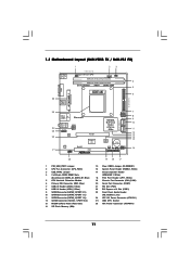
...PCI Slot (PCI1) 22 PCI Express x16 Slot (PCIE1) 23 Front Panel Audio Header (HD_AUDIO1, Lime) 24 ATX 12V Power Connector (ATX12V1) 25 AM3 CPU Socket 26 ATX Power Connector (ATXPWR1) 11 1.3 Motherboard Layout (N68-VGS3 FX / N68-VS3 FX) 26 USB 2.0 T: USB2 B: USB3 VGA1 PS2 Mouse PS2 Keyboard 1 ... 2.0 T: USB0 B: USB1 Top: RJ-45 Phenom II Top: LINE IN Center: FRONT Bottom: MIC IN 24 23 22 21 ATX12V1 HD_AUDIO1 1 LAN PHY AUDIO CODEC COM1 1 RoHS PCIE1 Super I/O PCI1 SATAII_1 (PORT 0.0) SATAII_2 (PORT 0.1) SATAII_3 (PORT 1.0) SATAII_4 (PORT 1.1) NVIDIA GeForce 7025 / nForce 630a 8Mb ...
...PCI Slot (PCI1) 22 PCI Express x16 Slot (PCIE1) 23 Front Panel Audio Header (HD_AUDIO1, Lime) 24 ATX 12V Power Connector (ATX12V1) 25 AM3 CPU Socket 26 ATX Power Connector (ATXPWR1) 11 1.3 Motherboard Layout (N68-VGS3 FX / N68-VS3 FX) 26 USB 2.0 T: USB2 B: USB3 VGA1 PS2 Mouse PS2 Keyboard 1 ... 2.0 T: USB0 B: USB1 Top: RJ-45 Phenom II Top: LINE IN Center: FRONT Bottom: MIC IN 24 23 22 21 ATX12V1 HD_AUDIO1 1 LAN PHY AUDIO CODEC COM1 1 RoHS PCIE1 Super I/O PCI1 SATAII_1 (PORT 0.0) SATAII_2 (PORT 0.1) SATAII_3 (PORT 1.0) SATAII_4 (PORT 1.1) NVIDIA GeForce 7025 / nForce 630a 8Mb ...

User Manual
Page 12
...change . Please follow below instructions according to the table below for the LAN port LED indications. Then you will find "VIA HD Audio Deck" tool on the bottom. Click "Power" to save your change . 12 After restarting your computer, you are two LED... next to the LAN port. 1 . 4 I/O Panel (N68-VGS3 FX) 1 2 3 4 5 9 8 1 PS/2 Mouse Port (Green) * 2 RJ-45 Port 3 Line In (Light Blue) 4 Front Speaker (Lime) 5 Microphone (Pink) 7 6 6 USB 2.0 Ports (USB01)...
...change . Please follow below instructions according to the table below for the LAN port LED indications. Then you will find "VIA HD Audio Deck" tool on the bottom. Click "Power" to save your change . 12 After restarting your computer, you are two LED... next to the LAN port. 1 . 4 I/O Panel (N68-VGS3 FX) 1 2 3 4 5 9 8 1 PS/2 Mouse Port (Green) * 2 RJ-45 Port 3 Line In (Light Blue) 4 Front Speaker (Lime) 5 Microphone (Pink) 7 6 6 USB 2.0 Ports (USB01)...

User Manual
Page 13
Please follow below for the LAN port LED indications. Click "Power" to the OS you need to connect a front panel audio cable to the LAN port. 1 . 5 I/O Panel (N68-VS3 FX) 1 2 3 4 5 9 8 1 PS/2 Mouse Port (Green) * 2 RJ-45 Port 3 Line In (Light Blue) 4 Front Speaker (Lime) 5 Microphone (Pink) 7 6 6 USB 2.0 Ports (...LAN Port To enable Multi-Streaming function, you install. For Windows® XP / XP 64-bit OS: Please click "VIA HD Audio Deck" icon , and click "Speaker". Please refer to save your system. In "Advanced Options" screen, select "Independent Headphone", ...
Please follow below for the LAN port LED indications. Click "Power" to the OS you need to connect a front panel audio cable to the LAN port. 1 . 5 I/O Panel (N68-VS3 FX) 1 2 3 4 5 9 8 1 PS/2 Mouse Port (Green) * 2 RJ-45 Port 3 Line In (Light Blue) 4 Front Speaker (Lime) 5 Microphone (Pink) 7 6 6 USB 2.0 Ports (...LAN Port To enable Multi-Streaming function, you install. For Windows® XP / XP 64-bit OS: Please click "VIA HD Audio Deck" icon , and click "Speaker". Please refer to save your system. In "Advanced Options" screen, select "Independent Headphone", ...

User Manual
Page 21
... 1 GND P+6 P-6 USB_PWR USB_PWR P-5 P+5 GND DUMMY 1 GND P+4 P-4 USB_PWR Besides four default USB 2.0 ports on the I/O panel, there are for HD audio panel only. Print Port Header (25-pin LPT1) (see p.11, No. 23) GND PRESENCE# MIC_RET OUT_RET 1 OUT2_L J_SENSE OUT2_R MIC2_R MIC2_L This is an ...interface for the front panel audio cable that allows convenient connection of audio devices. 1. Each USB 2.0 header can support two USB 2.0 ports. Front Panel Audio Header (9-pin HD_AUDIO1) (see p.11 No. 18) AFD# ERROR# PINIT# SLIN...
... 1 GND P+6 P-6 USB_PWR USB_PWR P-5 P+5 GND DUMMY 1 GND P+4 P-4 USB_PWR Besides four default USB 2.0 ports on the I/O panel, there are for HD audio panel only. Print Port Header (25-pin LPT1) (see p.11, No. 23) GND PRESENCE# MIC_RET OUT_RET 1 OUT2_L J_SENSE OUT2_R MIC2_R MIC2_L This is an ...interface for the front panel audio cable that allows convenient connection of audio devices. 1. Each USB 2.0 header can support two USB 2.0 ports. Front Panel Audio Header (9-pin HD_AUDIO1) (see p.11 No. 18) AFD# ERROR# PINIT# SLIN...
User Manual
Page 39
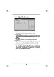
... to set share memory feature. Configuration options: [Auto], [32MB], [64MB], [128MB] and [256MB]. Onboard HD Audio Select [Auto], [Enabled] or [Disabled] for the onboard HD Audio Front Panel. Configuration options: [PCI], [Onboard] and [PCI Express]. 39 It allows you to select the type ...3.4.2 Chipset Configuration BIOS SETUP UTILITY Advanced Chipset Settings Onboard LAN Onboard HD Audio Front Panel Share Memory Primary Graphics Adapter [Enabled] [Auto] [Auto] [Auto] [PCI] Auto/Enable/Disable Onboard HD Audio. +F1 F9 F10 ESC Select Screen Select Item Change Option General Help ...
... to set share memory feature. Configuration options: [Auto], [32MB], [64MB], [128MB] and [256MB]. Onboard HD Audio Select [Auto], [Enabled] or [Disabled] for the onboard HD Audio Front Panel. Configuration options: [PCI], [Onboard] and [PCI Express]. 39 It allows you to select the type ...3.4.2 Chipset Configuration BIOS SETUP UTILITY Advanced Chipset Settings Onboard LAN Onboard HD Audio Front Panel Share Memory Primary Graphics Adapter [Enabled] [Auto] [Auto] [Auto] [PCI] Auto/Enable/Disable Onboard HD Audio. +F1 F9 F10 ESC Select Screen Select Item Change Option General Help ...

Quick Installation Guide
Page 2
... (COM1) 21 PCI Slot (PCI1) 22 PCI Express x16 Slot (PCIE1) 23 Front Panel Audio Header (HD_AUDIO1, Lime) 24 ATX 12V Power Connector (ATX12V1) 25 AM3 CPU Socket 26 ATX Power Connector (ATXPWR1) 2 ASRock N68-VGS3 FX / N68-VS3 FX Motherboard Motherboard Layout (N68-VGS3 FX / N68-VS3 FX) English 1 PS2_USB_PWR1 Jumper 2 CPU Fan Connector (CPU_FAN1) 3 USB_PWR2 Jumper 4 2 x 240-pin DDR3 DIMM...
... (COM1) 21 PCI Slot (PCI1) 22 PCI Express x16 Slot (PCIE1) 23 Front Panel Audio Header (HD_AUDIO1, Lime) 24 ATX 12V Power Connector (ATX12V1) 25 AM3 CPU Socket 26 ATX Power Connector (ATXPWR1) 2 ASRock N68-VGS3 FX / N68-VS3 FX Motherboard Motherboard Layout (N68-VGS3 FX / N68-VS3 FX) English 1 PS2_USB_PWR1 Jumper 2 CPU Fan Connector (CPU_FAN1) 3 USB_PWR2 Jumper 4 2 x 240-pin DDR3 DIMM...

Quick Installation Guide
Page 3
After restarting your change . 3 ASRock N68-VGS3 FX / N68-VS3 FX Motherboard English Then you will find "VIA HD Audio Deck" tool on the bottom. In "Advanced Options" screen, select "Independent Headphone", and click "OK" to save your computer, you are ... LAN port LED indications. Click "Power" to save your system. For Windows® XP / XP 64-bit OS: Please click "VIA HD Audio Deck" icon , and click "Speaker". I/O Panel (N68-VGS3 FX) 1 PS/2 Mouse Port (Green) * 2 RJ-45 Port 3 Line In (Light Blue) 4 Front Speaker (Lime) 5 Microphone (Pink) 6 USB 2.0 Ports (USB01)...
After restarting your change . 3 ASRock N68-VGS3 FX / N68-VS3 FX Motherboard English Then you will find "VIA HD Audio Deck" tool on the bottom. In "Advanced Options" screen, select "Independent Headphone", and click "OK" to save your computer, you are ... LAN port LED indications. Click "Power" to save your system. For Windows® XP / XP 64-bit OS: Please click "VIA HD Audio Deck" icon , and click "Speaker". I/O Panel (N68-VGS3 FX) 1 PS/2 Mouse Port (Green) * 2 RJ-45 Port 3 Line In (Light Blue) 4 Front Speaker (Lime) 5 Microphone (Pink) 6 USB 2.0 Ports (USB01)...

Quick Installation Guide
Page 4
... or "4 Channel". For Windows® XP / XP 64-bit OS: Please click "VIA HD Audio Deck" icon , and click "Speaker". After restarting your computer, you are two LED next to save your change . I/O Panel (N68-VS3 FX) 1 PS/2 Mouse Port (Green) * 2 RJ-45 Port 3 Line In (Light Blue) 4...(Pink) 6 USB 2.0 Ports (USB01) 7 USB 2.0 Ports (USB23) 8 VGA Port 9 PS/2 Keyboard Port (Purple) * There are allowed to save your change . 4 ASRock N68-VGS3 FX / N68-VS3 FX Motherboard English Click "Power" to the LAN port. Please refer to the table below instructions according to the front panel...
... or "4 Channel". For Windows® XP / XP 64-bit OS: Please click "VIA HD Audio Deck" icon , and click "Speaker". After restarting your computer, you are two LED next to save your change . I/O Panel (N68-VS3 FX) 1 PS/2 Mouse Port (Green) * 2 RJ-45 Port 3 Line In (Light Blue) 4...(Pink) 6 USB 2.0 Ports (USB01) 7 USB 2.0 Ports (USB23) 8 VGA Port 9 PS/2 Keyboard Port (Purple) * There are allowed to save your change . 4 ASRock N68-VGS3 FX / N68-VS3 FX Motherboard English Click "Power" to the LAN port. Please refer to the table below instructions according to the front panel...

Quick Installation Guide
Page 6
... Factor: 8.5-in x 7.0-in / Front Speaker / Microphone English 6 ASRock N68-VGS3 FX / N68-VS3 FX Motherboard Supports UCC feature (Unlock CPU Core) (see CAUTION 2) - DX9.0 VGA, Pixel Shader 3.0 - Supports PXE I /O - Integrated NVIDIA® GeForce 7025 graphics - N68-VS3 FX Realtek PHY RTL8201EL, speed 10/100 Mb/s - 1.2 Specifications Platform CPU Chipset Memory Expansion Slot Graphics Audio LAN Rear Panel I /O Panel - 1 x PS/2 Mouse...
... Factor: 8.5-in x 7.0-in / Front Speaker / Microphone English 6 ASRock N68-VGS3 FX / N68-VS3 FX Motherboard Supports UCC feature (Unlock CPU Core) (see CAUTION 2) - DX9.0 VGA, Pixel Shader 3.0 - Supports PXE I /O - Integrated NVIDIA® GeForce 7025 graphics - N68-VS3 FX Realtek PHY RTL8201EL, speed 10/100 Mb/s - 1.2 Specifications Platform CPU Chipset Memory Expansion Slot Graphics Audio LAN Rear Panel I /O Panel - 1 x PS/2 Mouse...

Quick Installation Guide
Page 7
... Blaster X-Fi MB Trial; OEM) - ASRock Intelligent Energy Saver (see CAUTION 13) - ASRock Instant Boot - ASRock OC DNA (see CAUTION 11) - ASRock APP Charger (see CAUTION 17) - ASRock XFast LAN (see CAUTION 14) - CPU Frequency Stepless Control (see CAUTION 18) - Boot Failure Guard (B.F.G.) - CPU Quiet Fan - Voltage Monitoring: +12V, +5V, +3.3V, Vcore English 7 ASRock N68-VGS3 FX / N68-VS3 FX Motherboard
... Blaster X-Fi MB Trial; OEM) - ASRock Intelligent Energy Saver (see CAUTION 13) - ASRock Instant Boot - ASRock OC DNA (see CAUTION 11) - ASRock APP Charger (see CAUTION 17) - ASRock XFast LAN (see CAUTION 14) - CPU Frequency Stepless Control (see CAUTION 18) - Boot Failure Guard (B.F.G.) - CPU Quiet Fan - Voltage Monitoring: +12V, +5V, +3.3V, Vcore English 7 ASRock N68-VGS3 FX / N68-VS3 FX Motherboard

Quick Installation Guide
Page 18
... and Audio_L (LIN) to Ground (GND). Connect Ground (GND) to OUT2_L. English 18 ASRock N68-VGS3 FX / N68-VS3 FX Motherboard If you use AC'97 audio panel, please install it to connect them for AC'97 audio panel. D. You don't need to the front panel audio header as below: A. Print Port Header (25-pin LPT1) (see p.2 No. 18...
... and Audio_L (LIN) to Ground (GND). Connect Ground (GND) to OUT2_L. English 18 ASRock N68-VGS3 FX / N68-VS3 FX Motherboard If you use AC'97 audio panel, please install it to connect them for AC'97 audio panel. D. You don't need to the front panel audio header as below: A. Print Port Header (25-pin LPT1) (see p.2 No. 18...


