User Manual
Page 6
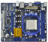
...memory: 8GB (see CAUTION 4) - N68-VGS3 FX Realtek Giga PHY RTL8211CL, speed 10/100/1000 Mb/s - HD Audio Jack: Line in , 21.6 cm x 17.8 cm - 1.2 Specifications Platform CPU Chipset Memory Expansion Slot Graphics Audio ...800 non-ECC, un-buffered memory (see CAUTION 5) - 2 x DDR3 DIMM slots - N68-VS3 FX Realtek PHY RTL8201EL, speed 10/100 Mb/s - Max. DX9.0 VGA, Pixel Shader 3.0 -...memory 256MB (see CAUTION 3) - NVIDIA® GeForce 7025 / nForce 630a - Supports UCC feature (Unlock CPU Core) (see CAUTION 8) - Support for AM3 processors: AMD PhenomTM II X6 / X4 / X3 /...
...memory: 8GB (see CAUTION 4) - N68-VGS3 FX Realtek Giga PHY RTL8211CL, speed 10/100/1000 Mb/s - HD Audio Jack: Line in , 21.6 cm x 17.8 cm - 1.2 Specifications Platform CPU Chipset Memory Expansion Slot Graphics Audio ...800 non-ECC, un-buffered memory (see CAUTION 5) - 2 x DDR3 DIMM slots - N68-VS3 FX Realtek PHY RTL8201EL, speed 10/100 Mb/s - Max. DX9.0 VGA, Pixel Shader 3.0 -...memory 256MB (see CAUTION 3) - NVIDIA® GeForce 7025 / nForce 630a - Supports UCC feature (Unlock CPU Core) (see CAUTION 8) - Support for AM3 processors: AMD PhenomTM II X6 / X4 / X3 /...
User Manual
Page 11
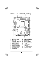
1.3 Motherboard Layout (N68-VGS3 FX / N68-VS3 FX) 26 USB 2.0 T: USB2 B: USB3 VGA1 PS2 Mouse PS2 Keyboard 1 2 3 17.8cm (7.0-in) Support 8-Core CPU 1 PS2_USB_PWR1 CPU_FAN1 1 USB_PWR2 DDR3_B1 (64 bit, 240-FpSin Bm8od0u0le) 4 DDR3_A1 (64 bit, 240-pin module) Dual Channel AM3+ DDR3 1600 5 IDE1 SOCKET AM3 6 21.6cm (8.5-in) AT X P W R 1 25 USB 2.0 T: USB0 B: USB1 Top: RJ-45 Phenom...) 21 PCI Slot (PCI1) 22 PCI Express x16 Slot (PCIE1) 23 Front Panel Audio Header (HD_AUDIO1, Lime) 24 ATX 12V Power Connector (ATX12V1) 25 AM3 CPU Socket 26 ATX Power Connector (ATXPWR1) 11
1.3 Motherboard Layout (N68-VGS3 FX / N68-VS3 FX) 26 USB 2.0 T: USB2 B: USB3 VGA1 PS2 Mouse PS2 Keyboard 1 2 3 17.8cm (7.0-in) Support 8-Core CPU 1 PS2_USB_PWR1 CPU_FAN1 1 USB_PWR2 DDR3_B1 (64 bit, 240-FpSin Bm8od0u0le) 4 DDR3_A1 (64 bit, 240-pin module) Dual Channel AM3+ DDR3 1600 5 IDE1 SOCKET AM3 6 21.6cm (8.5-in) AT X P W R 1 25 USB 2.0 T: USB0 B: USB1 Top: RJ-45 Phenom...) 21 PCI Slot (PCI1) 22 PCI Express x16 Slot (PCIE1) 23 Front Panel Audio Header (HD_AUDIO1, Lime) 24 ATX 12V Power Connector (ATX12V1) 25 AM3 CPU Socket 26 ATX Power Connector (ATXPWR1) 11

User Manual
Page 15
...pins. Then connect the CPU fan to a 90o angle. Step 2. Carefully insert the CPU into the socket to indicate that the CPU corner with the golden triangle matches the socket corner with each other. The lever clicks on the socket while you install the CPU into this motherboard, it ...4. You also need to spray thermal grease between the CPU and the heatsink to secure the CPU. 2.1 CPU Installation Step 1. DO NOT force the CPU into the socket until it is locked. Lever 90° Up STEP 1: Lift Up The Socket Lever CPU Golden Triangle Socker Corner Small Triangle STEP 2 / STEP ...
...pins. Then connect the CPU fan to a 90o angle. Step 2. Carefully insert the CPU into the socket to indicate that the CPU corner with the golden triangle matches the socket corner with each other. The lever clicks on the socket while you install the CPU into this motherboard, it ...4. You also need to spray thermal grease between the CPU and the heatsink to secure the CPU. 2.1 CPU Installation Step 1. DO NOT force the CPU into the socket until it is locked. Lever 90° Up STEP 1: Lift Up The Socket Lever CPU Golden Triangle Socker Corner Small Triangle STEP 2 / STEP ...

Quick Installation Guide
Page 2
Motherboard Layout (N68-VGS3 FX / N68-VS3 FX) English 1 PS2_USB_PWR1 Jumper 2 CPU Fan Connector (CPU_FAN1) 3 USB_PWR2 Jumper 4 2 x 240-pin DDR3 DIMM Slots (Dual Channel: DDR3_A1, DDR3_B1; Blue) 5 CPU Heatsink Retention Module 6 Primary IDE Connector (IDE1, Blue) 7 USB 2.0 Header (USB6_7, Blue) 8 USB 2.0 Header (USB4_5, Blue) 9 SATAII Connector (SATAII_2 (PORT 0.1)) 10 SATAII ...) 22 PCI Express x16 Slot (PCIE1) 23 Front Panel Audio Header (HD_AUDIO1, Lime) 24 ATX 12V Power Connector (ATX12V1) 25 AM3 CPU Socket 26 ATX Power Connector (ATXPWR1) 2 ASRock N68-VGS3 FX / N68-VS3 FX Motherboard
Motherboard Layout (N68-VGS3 FX / N68-VS3 FX) English 1 PS2_USB_PWR1 Jumper 2 CPU Fan Connector (CPU_FAN1) 3 USB_PWR2 Jumper 4 2 x 240-pin DDR3 DIMM Slots (Dual Channel: DDR3_A1, DDR3_B1; Blue) 5 CPU Heatsink Retention Module 6 Primary IDE Connector (IDE1, Blue) 7 USB 2.0 Header (USB6_7, Blue) 8 USB 2.0 Header (USB4_5, Blue) 9 SATAII Connector (SATAII_2 (PORT 0.1)) 10 SATAII ...) 22 PCI Express x16 Slot (PCIE1) 23 Front Panel Audio Header (HD_AUDIO1, Lime) 24 ATX 12V Power Connector (ATX12V1) 25 AM3 CPU Socket 26 ATX Power Connector (ATXPWR1) 2 ASRock N68-VGS3 FX / N68-VS3 FX Motherboard

Quick Installation Guide
Page 6
...Socket AM3+ processors (see CAUTION 5) - 2 x DDR3 DIMM slots - FSB 1000 MHz (2.0 GT/s) - NVIDIA® GeForce 7025 / nForce 630a - capacity of system memory: 8GB (see CAUTION 2) - shared memory 256MB (see CAUTION 4) - Supports PXE I /O - Supports 8-Core CPU...CPU Chipset Memory Expansion Slot Graphics Audio LAN Rear Panel I /O Panel - 1 x PS/2 Mouse Port - 1 x PS/2 Keyboard Port - 1 x VGA Port - 4 x Ready-to 1920x1440 @ 60Hz - 5.1 CH HD Audio (VIA® VT1705 Audio Codec) - Micro ATX Form Factor: 8.5-in x 7.0-in / Front Speaker / Microphone English 6 ASRock N68-VGS3 FX / N68-VS3 FX...
...Socket AM3+ processors (see CAUTION 5) - 2 x DDR3 DIMM slots - FSB 1000 MHz (2.0 GT/s) - NVIDIA® GeForce 7025 / nForce 630a - capacity of system memory: 8GB (see CAUTION 2) - shared memory 256MB (see CAUTION 4) - Supports PXE I /O - Supports 8-Core CPU...CPU Chipset Memory Expansion Slot Graphics Audio LAN Rear Panel I /O Panel - 1 x PS/2 Mouse Port - 1 x PS/2 Keyboard Port - 1 x VGA Port - 4 x Ready-to 1920x1440 @ 60Hz - 5.1 CH HD Audio (VIA® VT1705 Audio Codec) - Micro ATX Form Factor: 8.5-in x 7.0-in / Front Speaker / Microphone English 6 ASRock N68-VGS3 FX / N68-VS3 FX...

Quick Installation Guide
Page 12
... with the golden triangle matches the socket corner with each other. Then connect the CPU fan to improve heat dissipation. English 12 ASRock N68-VGS3 FX / N68-VS3 FX Motherboard Carefully insert the CPU into the socket to the instruction manuals of the pins. Step 3. Position the CPU directly above the socket such that the CPU and the heatsink are securely fastened and...
... with the golden triangle matches the socket corner with each other. Then connect the CPU fan to improve heat dissipation. English 12 ASRock N68-VGS3 FX / N68-VS3 FX Motherboard Carefully insert the CPU into the socket to the instruction manuals of the pins. Step 3. Position the CPU directly above the socket such that the CPU and the heatsink are securely fastened and...


