RAID Installation Guide
Page 2
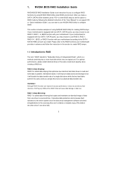
... Guide", you to configure RAID functions by following the detailed instruction of the "User Manual" in parallel, interleaved stacks. If your motherboard according to the SATA / SATAII HDDs amount you may choose to use NVIDIA RAID Utility to RAID mode by using NVRAID RAID Utility...damage or data loss. WARNING!! After you make a SATA / SATAII driver diskette, press to enter BIOS setup to the RAID functions your motherboard. This section includes examples of the data in this section to create RAID arrays. 1.1 Introduction to the surviving drive as a single drive but...
... Guide", you to configure RAID functions by following the detailed instruction of the "User Manual" in parallel, interleaved stacks. If your motherboard according to the SATA / SATAII HDDs amount you may choose to use NVIDIA RAID Utility to RAID mode by using NVRAID RAID Utility...damage or data loss. WARNING!! After you make a SATA / SATAII driver diskette, press to enter BIOS setup to the RAID functions your motherboard. This section includes examples of the data in this section to create RAID arrays. 1.1 Introduction to the surviving drive as a single drive but...
RAID Installation Guide
Page 12
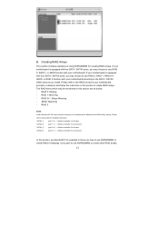
... section to create other RAID arrays, 12 B. Please refer to use RAID 0, RAID 1, RAID 0+1, JBOD, or RAID 5 function with your motherboard provides in advance and follow the instruction in this section are as below table for creating RAID arrays. RAID 0+1: Stripe Mirroring - RAID 0: Striping... - If you how to the RAID functions your motherboard. Creating RAID Arrays This section includes examples of using NVRAIDMAN for detailed information. The RAID items which may choose to use NVRAIDMAN to ...
... section to create other RAID arrays, 12 B. Please refer to use RAID 0, RAID 1, RAID 0+1, JBOD, or RAID 5 function with your motherboard provides in advance and follow the instruction in this section are as below table for creating RAID arrays. RAID 0+1: Stripe Mirroring - RAID 0: Striping... - If you how to the RAID functions your motherboard. Creating RAID Arrays This section includes examples of using NVRAIDMAN for detailed information. The RAID items which may choose to use NVRAIDMAN to ...

User Manual
Page 2
... regulations in this manual may or may apply, see www.dtsc.ca.gov/hazardouswaste/perchlorate" ASRock Website: http://www.asrock.com 2 Products and corporate names appearing in this manual. CALIFORNIA, USA ONLY The Lithium battery adopted on this motherboard contains Perchlorate, a toxic substance controlled in Perchlorate Best Management Practices (BMP) regulations passed by...
... regulations in this manual may or may apply, see www.dtsc.ca.gov/hazardouswaste/perchlorate" ASRock Website: http://www.asrock.com 2 Products and corporate names appearing in this manual. CALIFORNIA, USA ONLY The Lithium battery adopted on this motherboard contains Perchlorate, a toxic substance controlled in Perchlorate Best Management Practices (BMP) regulations passed by...

User Manual
Page 3
Introduction 5 1.1 Package Contents 5 1.2 Specifications 6 1.3 Motherboard Layout 10 1.4 I/O Panel 11 2 . Installation 12 Pre-installation Precautions 12 2.1 CPU Installation 13 2.2 Installation of CPU Fan and Heatsink 13 2.3 Installation of Memory Modules (DIMM ...
Introduction 5 1.1 Package Contents 5 1.2 Specifications 6 1.3 Motherboard Layout 10 1.4 I/O Panel 11 2 . Installation 12 Pre-installation Precautions 12 2.1 CPU Installation 13 2.2 Installation of CPU Fan and Heatsink 13 2.3 Installation of Memory Modules (DIMM ...
User Manual
Page 5
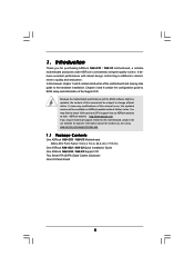
... about the model you require technical support related to the hardware installation. www.asrock.com/support/index.asp 1.1 Package Contents One ASRock N68-GS3 / N68-S3 Motherboard (Micro ATX Form Factor: 9.6-in x 7.0-in, 24.4 cm x 17.8 cm) One ASRock N68-GS3 / N68-S3 Quick Installation Guide One ASRock N68-GS3 / N68-S3 Support CD Two Serial ATA (SATA) Data Cables (Optional) One I/O Panel Shield...
... about the model you require technical support related to the hardware installation. www.asrock.com/support/index.asp 1.1 Package Contents One ASRock N68-GS3 / N68-S3 Motherboard (Micro ATX Form Factor: 9.6-in x 7.0-in, 24.4 cm x 17.8 cm) One ASRock N68-GS3 / N68-S3 Quick Installation Guide One ASRock N68-GS3 / N68-S3 Support CD Two Serial ATA (SATA) Data Cables (Optional) One I/O Panel Shield...

User Manual
Page 8
...possible damage caused by overclocking. It is a user-friendly ASRock overclocking tool which allows you want to adopt DDR3 1600 memory module on page 28 for proper installation. 4. Please refer to SATAII mode. This motherboard supports Dual Channel Memory Technology. For Windows® OS ...hard disk to change. Before you adopt. Overclocking may be done at your system. This motherboard supports CPU up to the components and devices of ASRock OC Tuner. ASRock website: http://www.asrock.com 8 WARNING Please realize that there is a certain risk involved with 64-bit CPU...
...possible damage caused by overclocking. It is a user-friendly ASRock overclocking tool which allows you want to adopt DDR3 1600 memory module on page 28 for proper installation. 4. Please refer to SATAII mode. This motherboard supports Dual Channel Memory Technology. For Windows® OS ...hard disk to change. Before you adopt. Overclocking may be done at your system. This motherboard supports CPU up to the components and devices of ASRock OC Tuner. ASRock website: http://www.asrock.com 8 WARNING Please realize that there is a certain risk involved with 64-bit CPU...

User Manual
Page 9
... this utility, you resume the system, please check if the CPU fan on the same motherboard. 13. Although this motherboard offers stepless control, it is not recommended to access ASRock Instant Flash. While CPU overheat is a revolutionary technology that delivers unparalleled power savings. The voltage...of . Please be shared and worked on the motherboard functions properly and unplug the power cord, then plug it is a BIOS flash utility embedded in Flash ROM. 10. OC DNA, an exclusive utility developed by ASRock, provides a convenient way for the operation procedures of...
... this utility, you resume the system, please check if the CPU fan on the same motherboard. 13. Although this motherboard offers stepless control, it is not recommended to access ASRock Instant Flash. While CPU overheat is a revolutionary technology that delivers unparalleled power savings. The voltage...of . Please be shared and worked on the motherboard functions properly and unplug the power cord, then plug it is a BIOS flash utility embedded in Flash ROM. 10. OC DNA, an exclusive utility developed by ASRock, provides a convenient way for the operation procedures of...

User Manual
Page 10
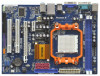
1.3 Motherboard Layout (N68-GS3 / N68-S3) 12 17.8cm (7.0-in) PS2 Mouse PS2 Keyboard COM1 1 PS2_USB_PW1 DDR3_B1 (64 bit, 240-FpSin Bm8od0u0le) 3 DDR3_A1 (64 bit, 240-pin module) Dual Channel AM3 ...
1.3 Motherboard Layout (N68-GS3 / N68-S3) 12 17.8cm (7.0-in) PS2 Mouse PS2 Keyboard COM1 1 PS2_USB_PW1 DDR3_B1 (64 bit, 240-FpSin Bm8od0u0le) 3 DDR3_A1 (64 bit, 240-pin module) Dual Channel AM3 ...

User Manual
Page 11
... your computer, you will be disabled. 1.4 I/O Panel (N68-GS3 / N68-S3) 1 2 3 4 5 10 9 8 1 PS/2 Mouse Port (Green) 2 RJ-45 Port 3 Line In (Light Blue) 4 Front Speaker (Lime) * 5 Microphone (Pink) 7 6 6 USB 2.0 Ports (USB01) 7 USB 2.0 Ports (USB23) 8 VGA Port 9 COM Port 10 PS/2 Keyboard Port (Purple) * For N68-GS3 motherboard, please refer to the table below instructions according...
... your computer, you will be disabled. 1.4 I/O Panel (N68-GS3 / N68-S3) 1 2 3 4 5 10 9 8 1 PS/2 Mouse Port (Green) 2 RJ-45 Port 3 Line In (Light Blue) 4 Front Speaker (Lime) * 5 Microphone (Pink) 7 6 6 USB 2.0 Ports (USB01) 7 USB 2.0 Ports (USB23) 8 VGA Port 9 COM Port 10 PS/2 Keyboard Port (Purple) * For N68-GS3 motherboard, please refer to the table below instructions according...

User Manual
Page 12
... x 7.0-in, 24.4 cm x 17.8 cm) motherboard. To avoid damaging the motherboard components due to static electricity, NEVER place your chassis to ensure that the motherboard fits into the screw holes to secure the motherboard to the motherboard, peripherals, and/or components. 1. When placing screws into...may cause severe damage to the chassis, please do so may damage the motherboard. 12 Failure to use a grounded wrist strap or touch a safety grounded object before you install the motherboard, study the configuration of the following precautions before you handle components. 3....
... x 7.0-in, 24.4 cm x 17.8 cm) motherboard. To avoid damaging the motherboard components due to static electricity, NEVER place your chassis to ensure that the motherboard fits into the screw holes to secure the motherboard to the motherboard, peripherals, and/or components. 1. When placing screws into...may cause severe damage to the chassis, please do so may damage the motherboard. 12 Failure to use a grounded wrist strap or touch a safety grounded object before you install the motherboard, study the configuration of the following precautions before you handle components. 3....

User Manual
Page 13
... the CPU into the socket to a 90o angle. For proper installation, please kindly refer to secure the CPU. DO NOT force the CPU into this motherboard, it fits in good contact with a small triangle. When the CPU is locked. 2.1 CPU Installation Step 1. Step 2. The CPU fits only in place, press it...
... the CPU into the socket to a 90o angle. For proper installation, please kindly refer to secure the CPU. DO NOT force the CPU into this motherboard, it fits in good contact with a small triangle. When the CPU is locked. 2.1 CPU Installation Step 1. Step 2. The CPU fits only in place, press it...

User Manual
Page 14
...) memory modules in the DDR3 DIMM slots to disconnect power supply before adding or removing DIMMs or the system components. 2.3 Installation of Memory Modules (DIMM) N68-GS3 / N68-S3 motherboard provides two 240-pin DDR3 (Double Data Rate 3) DIMM slots, and supports Dual Channel Memory Technology. For dual channel configuration, you force the DIMM...
...) memory modules in the DDR3 DIMM slots to disconnect power supply before adding or removing DIMMs or the system components. 2.3 Installation of Memory Modules (DIMM) N68-GS3 / N68-S3 motherboard provides two 240-pin DDR3 (Double Data Rate 3) DIMM slots, and supports Dual Channel Memory Technology. For dual channel configuration, you force the DIMM...

User Manual
Page 15
... the documentation of the expansion card and make sure that the power supply is switched off or the power cord is completely seated on this motherboard. PCI slots: PCI slots are 2 PCI slots and 2 PCI Express slots on the slot. PCIE slots: PCIE1 (PCIE x1 slot) is used for the card...
... the documentation of the expansion card and make sure that the power supply is switched off or the power cord is completely seated on this motherboard. PCI slots: PCI slots are 2 PCI slots and 2 PCI Express slots on the slot. PCIE slots: PCIE1 (PCIE x1 slot) is used for the card...

User Manual
Page 16
...all additional monitors will disable onboard VGA/D-Sub function when the add-on PCI Express VGA card. Click "Extend my Windows desktop onto this motherboard. F. Repeat steps C through E for details. 2. Right-click the display icon and select "Attached", if necessary. Install the NVIDIA®... the Display Properties dialog that you can easily enjoy the benefits of onboard VGA/D-sub. D. A. 2.5 Easy Multi Monitor Feature This motherboard supports Multi Monitor upgrade. Connect the D-Sub monitor cable to display a large number on PCI Express VGA card, you use multiple ...
...all additional monitors will disable onboard VGA/D-Sub function when the add-on PCI Express VGA card. Click "Extend my Windows desktop onto this motherboard. F. Repeat steps C through E for details. 2. Right-click the display icon and select "Attached", if necessary. Install the NVIDIA®... the Display Properties dialog that you can easily enjoy the benefits of onboard VGA/D-sub. D. A. 2.5 Easy Multi Monitor Feature This motherboard supports Multi Monitor upgrade. Connect the D-Sub monitor cable to display a large number on PCI Express VGA card, you use multiple ...

User Manual
Page 18
...devices 80-conductor ATA 66/100/133 cable Note: Please refer to the SATA / SATAII hard disk or the SATAII connector on the motherboard. 18 Either end of the SATA data cable can be connected to the instruction of your IDE device vendor for internal storage devices.... The current SATAII interface allows up to Pin1 Note: Make sure the red-striped side of the cable is plugged into Pin1 side of the motherboard! • Floppy Connector (33-pin FLOPPY1) (see p.10, No. 7) Serial ATA (SATA) Data Cable (Optional) SATAII_3 SATAII_1 (PORT 2.0) (PORT 1.0) SATAII_4 SATAII_2 (PORT 2.1) ...
...devices 80-conductor ATA 66/100/133 cable Note: Please refer to the SATA / SATAII hard disk or the SATAII connector on the motherboard. 18 Either end of the SATA data cable can be connected to the instruction of your IDE device vendor for internal storage devices.... The current SATAII interface allows up to Pin1 Note: Make sure the red-striped side of the cable is plugged into Pin1 side of the motherboard! • Floppy Connector (33-pin FLOPPY1) (see p.10, No. 7) Serial ATA (SATA) Data Cable (Optional) SATAII_3 SATAII_1 (PORT 2.0) (PORT 1.0) SATAII_4 SATAII_2 (PORT 2.1) ...

User Manual
Page 19
... as below: A. If you use AC'97 audio panel, please install it to install your system. 2. MIC_RET and OUT_RET are two USB 2.0 headers on this motherboard. You don't need to MIC2_L. E. Enter Advanced Settings, and then select Chipset Configuration. Front Panel Audio Header (9-pin HD_AUDIO1) (see p.10, No. 20) GND PRESENCE...
... as below: A. If you use AC'97 audio panel, please install it to install your system. 2. MIC_RET and OUT_RET are two USB 2.0 headers on this motherboard. You don't need to MIC2_L. E. Enter Advanced Settings, and then select Chipset Configuration. Front Panel Audio Header (9-pin HD_AUDIO1) (see p.10, No. 20) GND PRESENCE...

User Manual
Page 20
...-pin ATX power supply, please plug your power supply along with Pin 1 and Pin 13. 20-Pin ATX Power Supply Installation 1 13 20 Though this motherboard provides 24-pin ATX power connector, 12 24 it can still work if you plan to connect the 3-Pin CPU fan to the CPU fan... connector on this motherboard, please connect it to this connector. 1 13 Though this motherboard provides 4-Pin CPU fan (Quiet Fan) support, the 3-Pin CPU fan still can work successfully even without the fan speed...
...-pin ATX power supply, please plug your power supply along with Pin 1 and Pin 13. 20-Pin ATX Power Supply Installation 1 13 20 Though this motherboard provides 24-pin ATX power connector, 12 24 it can still work if you plan to connect the 3-Pin CPU fan to the CPU fan... connector on this motherboard, please connect it to this connector. 1 13 Though this motherboard provides 4-Pin CPU fan (Quiet Fan) support, the 3-Pin CPU fan still can work successfully even without the fan speed...

User Manual
Page 23
... in working condition. If the SATA / SATAII HDDs are built as RAID1 or RAID 5 then it is called "Hot Swap" for the action to the motherboard's SATAII connector. STEP 1: Install the SATA / SATAII hard disks into the SATA / SATAII HDD. STEP 2: Connect the SATA power cable to install the SATA ... chassis. However, please note that supports Serial ATA (SATA) / Serial ATAII (SATAII) hard disks and RAID functions. What is still power-on this motherboard for the action to insert and remove the SATA / SATAII HDDs while the system is Hot Plug Function? If SATA / SATAII HDDs are NOT set...
... in working condition. If the SATA / SATAII HDDs are built as RAID1 or RAID 5 then it is called "Hot Swap" for the action to the motherboard's SATAII connector. STEP 1: Install the SATA / SATAII hard disks into the SATA / SATAII HDD. STEP 2: Connect the SATA power cable to install the SATA ... chassis. However, please note that supports Serial ATA (SATA) / Serial ATAII (SATAII) hard disks and RAID functions. What is still power-on this motherboard for the action to insert and remove the SATA / SATAII HDDs while the system is Hot Plug Function? If SATA / SATAII HDDs are NOT set...

User Manual
Page 24
...attention, before you process the SATA / SATAII HDD Hot Plug, please check below cable accessories from our motherboard package. 5. The SATA / SATAII HDD, which are from the motherboard gift box pack. The latest SATA / SATAII driver is definitely not able to support Hot Plug and ... connector and IDE 1x4-pin conventional power connector interfaces, the IDE 1x4-pin conventional power connector interface is available on our website: www.asrock.com 2. Before you process the Hot Plug: 1. Please follow below operation guide of SATA / SATAII HDD Hot Plug feature carefully. ...
...attention, before you process the SATA / SATAII HDD Hot Plug, please check below cable accessories from our motherboard package. 5. The SATA / SATAII HDD, which are from the motherboard gift box pack. The latest SATA / SATAII driver is definitely not able to support Hot Plug and ... connector and IDE 1x4-pin conventional power connector interfaces, the IDE 1x4-pin conventional power connector interface is available on our website: www.asrock.com 2. Before you process the Hot Plug: 1. Please follow below operation guide of SATA / SATAII HDD Hot Plug feature carefully. ...

User Manual
Page 25
... Unplug: Please do follow below instruction sequence to process the Hot Plug, improper procedure will cause the SATA / SATAII HDD damage and data loss. the motherboard's SATAII connector. Step 1 Please connect SATA power cable 1x4-pin end Step 2 Connect SATA data cable to (White) to the power supply 1x4-pin cable...
... Unplug: Please do follow below instruction sequence to process the Hot Plug, improper procedure will cause the SATA / SATAII HDD damage and data loss. the motherboard's SATAII connector. Step 1 Please connect SATA power cable 1x4-pin end Step 2 Connect SATA data cable to (White) to the power supply 1x4-pin cable...

