User Manual
Page 10
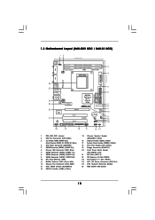
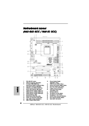
... (PCI1- 2) 22 PCI Express x16 Slot (PCIE2) 23 PCI Express x1 Slot (PCIE1) 24 ATX 12V Power Connector (ATX12V1) 25 CPU Heatsink Retention Module 26 AM3 938-Pin CPU Socket 10 1.3 Motherboard Layout (N68-GS3 UCC / N68-S3 UCC) 12 17.8cm (7.0-in) PS2 Mouse PS2 Keyboard COM1 1 PS2_USB_PW1 DDR3_B1 (64 bit, 240-FpSin Bm8od0u0le) 3 DDR3_A1 (64 bit...
... (PCI1- 2) 22 PCI Express x16 Slot (PCIE2) 23 PCI Express x1 Slot (PCIE1) 24 ATX 12V Power Connector (ATX12V1) 25 CPU Heatsink Retention Module 26 AM3 938-Pin CPU Socket 10 1.3 Motherboard Layout (N68-GS3 UCC / N68-S3 UCC) 12 17.8cm (7.0-in) PS2 Mouse PS2 Keyboard COM1 1 PS2_USB_PW1 DDR3_B1 (64 bit, 240-FpSin Bm8od0u0le) 3 DDR3_A1 (64 bit...
User Manual
Page 13
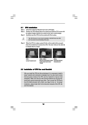
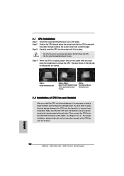
... to install a larger heatsink and cooling fan to indicate that the CPU corner with the golden triangle matches the socket corner with each other. The CPU fits only in good contact with a small triangle. DO NOT force the CPU into this motherboard, it is in place, press it fits in place.... Step 4. The lever clicks on the socket while you install the CPU into the socket to the instruction manuals of the CPU fan and the heatsink. 13 You also need to spray thermal grease between the CPU and the heatsink to the CPU FAN connector (CPU_FAN1, see Page 10, No. 2)....
... to install a larger heatsink and cooling fan to indicate that the CPU corner with the golden triangle matches the socket corner with each other. The CPU fits only in good contact with a small triangle. DO NOT force the CPU into this motherboard, it is in place, press it fits in place.... Step 4. The lever clicks on the socket while you install the CPU into the socket to the instruction manuals of the CPU fan and the heatsink. 13 You also need to spray thermal grease between the CPU and the heatsink to the CPU FAN connector (CPU_FAN1, see Page 10, No. 2)....
Quick Installation Guide
Page 2
Motherboard Layout (N68-GS3 UCC / N68-S3 UCC) English 1 PS2_USB_PW1 Jumper 2 CPU Fan Connector (CPU_FAN1) 3 2 x 240-pin DDR3 DIMM Slots (Dual Channel: DDR3_A1, DDR3_B1; Blue) 4 ATX Power Connector (ATXPWR1) 5 SATAII Connector (SATAII_2 (PORT 0.1)) 6 Primary IDE Connector (IDE1, ... (HD_AUDIO1, Lime) 21 PCI Slots (PCI1- 2) 22 PCI Express x16 Slot (PCIE2) 23 PCI Express x1 Slot (PCIE1) 24 ATX 12V Power Connector (ATX12V1) 25 CPU Heatsink Retention Module 26 AM3 938-Pin CPU Socket 2 ASRock N68-GS3 UCC / N68-S3 UCC Motherboard
Motherboard Layout (N68-GS3 UCC / N68-S3 UCC) English 1 PS2_USB_PW1 Jumper 2 CPU Fan Connector (CPU_FAN1) 3 2 x 240-pin DDR3 DIMM Slots (Dual Channel: DDR3_A1, DDR3_B1; Blue) 4 ATX Power Connector (ATXPWR1) 5 SATAII Connector (SATAII_2 (PORT 0.1)) 6 Primary IDE Connector (IDE1, ... (HD_AUDIO1, Lime) 21 PCI Slots (PCI1- 2) 22 PCI Express x16 Slot (PCIE2) 23 PCI Express x1 Slot (PCIE1) 24 ATX 12V Power Connector (ATX12V1) 25 CPU Heatsink Retention Module 26 AM3 938-Pin CPU Socket 2 ASRock N68-GS3 UCC / N68-S3 UCC Motherboard
Quick Installation Guide
Page 10
... the golden triangle matches the socket corner with each other. English 10 ASRock N68-GS3 UCC / N68-S3 UCC Motherboard DO NOT force the CPU into the socket to secure the CPU. Lever 90° Up CPU Golden Triangle STEP 1: Lift Up The Socket Lever Socker Corner Small Triangle STEP 2 / STEP 3: Match The CPU Golden Triangle To The Socket Corner Small Triangle STEP 4: Push...
... the golden triangle matches the socket corner with each other. English 10 ASRock N68-GS3 UCC / N68-S3 UCC Motherboard DO NOT force the CPU into the socket to secure the CPU. Lever 90° Up CPU Golden Triangle STEP 1: Lift Up The Socket Lever Socker Corner Small Triangle STEP 2 / STEP 3: Match The CPU Golden Triangle To The Socket Corner Small Triangle STEP 4: Push...


