

User Manual
Page 4
...1 1.1 Package Contents 1 1.2 Speciications 2 1.3 Motherboard Layout 5 1.4 I/O Panel 7 Chapter 2 Installation 8 2.1 Installing Memory Modules (SO-DIMM) 9 2.2 Expansion Slots (PCI Express Slots) 11 2.3 Jumpers Setup 12 2.4 Onboard Headers and Connectors 13 Chapter 3 Software and Utilities Operation 19 3.1 Installing Drivers 19 3.2 ASRock Live Update & APP Shop 20 3.2.1 UI Overview 20 3.2.2 Apps 21 3.2.3 BIOS & Drivers 24 3.2.4 Setting 25 Chapter 4 UEFI SETUP UTILITY 29 4.1 Introduction 29 4.1.1 UEFI Menu Bar 29 4.1.2 Navigation Keys 30 4.2 Main Screen 31
...1 1.1 Package Contents 1 1.2 Speciications 2 1.3 Motherboard Layout 5 1.4 I/O Panel 7 Chapter 2 Installation 8 2.1 Installing Memory Modules (SO-DIMM) 9 2.2 Expansion Slots (PCI Express Slots) 11 2.3 Jumpers Setup 12 2.4 Onboard Headers and Connectors 13 Chapter 3 Software and Utilities Operation 19 3.1 Installing Drivers 19 3.2 ASRock Live Update & APP Shop 20 3.2.1 UI Overview 20 3.2.2 Apps 21 3.2.3 BIOS & Drivers 24 3.2.4 Setting 25 Chapter 4 UEFI SETUP UTILITY 29 4.1 Introduction 29 4.1.1 UEFI Menu Bar 29 4.1.2 Navigation Keys 30 4.2 Main Screen 31
User Manual
Page 6
... updated, the content of the motherboard and step-by-step installation guides. In case any modiications of the sotware and utilities. Chapter 4 contains the coniguration guide of the BIOS setup. You may ind the latest VGA cards and CPU support list on ASRock's website without notice. ASRock website http://www.asrock.com. 1.1 Package Contents • ASRock N3150TM-ITX Motherboard (hin Mini-ITX Form Factor) • ASRock N3150TM-ITX Quick Installation Guide • ASRock N3150TM-ITX Support CD • 2 x Serial ATA (SATA) Data Cables (Optional) • 1 x SATA...
... updated, the content of the motherboard and step-by-step installation guides. In case any modiications of the sotware and utilities. Chapter 4 contains the coniguration guide of the BIOS setup. You may ind the latest VGA cards and CPU support list on ASRock's website without notice. ASRock website http://www.asrock.com. 1.1 Package Contents • ASRock N3150TM-ITX Motherboard (hin Mini-ITX Form Factor) • ASRock N3150TM-ITX Quick Installation Guide • ASRock N3150TM-ITX Support CD • 2 x Serial ATA (SATA) Data Cables (Optional) • 1 x SATA...

User Manual
Page 7
...-ray (BD) playback with max. resolution up to 1920x1200 @ 60Hz • Supports LVDS with HDMI Port English 2 1.2 Speciications Platform • hin Mini-ITX Form Factor • Solid Capacitor design • High Density Glass Fabric PCB CPU • Intel® Quad-Core Processor N3150 (up to the power limitation and PCIe bandwidth (x1), the VGA card is not supported. capacity of system memory: 16GB (see CAUTION...
...-ray (BD) playback with max. resolution up to 1920x1200 @ 60Hz • Supports LVDS with HDMI Port English 2 1.2 Speciications Platform • hin Mini-ITX Form Factor • Solid Capacitor design • High Density Glass Fabric PCB CPU • Intel® Quad-Core Processor N3150 (up to the power limitation and PCIe bandwidth (x1), the VGA card is not supported. capacity of system memory: 16GB (see CAUTION...
User Manual
Page 8
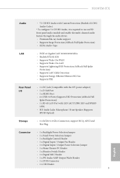
... x DC Jack (Compatible with the 19V power adapter) • 1 x D-Sub Port • 1 x HDMI Port • 4 x USB 3.0 Ports (Supports ESD Protection (ASRock Full Spike Protection)) • 1 x RJ-45 LAN Port with LED (ACT/LINK LED and SPEED LED) • HD Audio Jacks: Microphone / Front Speaker (Supports SPDIF Optical) Storage • 2 x SATA3 6.0 Gb/s Connectors, support NCQ, AHCI and Hot Plug Connector • 1 x Backlight Power Selection Jumper • 1 x Panel Power Selection Jumper • 1 x Backlight Control Header • 1 x Digital Input / Output Pin Header • 1 x Digital...
... x DC Jack (Compatible with the 19V power adapter) • 1 x D-Sub Port • 1 x HDMI Port • 4 x USB 3.0 Ports (Supports ESD Protection (ASRock Full Spike Protection)) • 1 x RJ-45 LAN Port with LED (ACT/LINK LED and SPEED LED) • HD Audio Jacks: Microphone / Front Speaker (Supports SPDIF Optical) Storage • 2 x SATA3 6.0 Gb/s Connectors, support NCQ, AHCI and Hot Plug Connector • 1 x Backlight Power Selection Jumper • 1 x Panel Power Selection Jumper • 1 x Backlight Control Header • 1 x Digital Input / Output Pin Header • 1 x Digital...

User Manual
Page 9
... LED Header • 1 x TPM Header • 1 x CPU Fan Connector (4-pin) • 1 x Chassis Fan Connector (4-pin) • 1 x SATA Power Connector • 1 x Internal Power Header • 1 x Front Panel Audio Connector • 1 x Analog Surround Audio Connector • 3 x USB 2.0 Headers (Support 5 USB 2.0 ports) (Supports ESD Protection (ASRock Full Spike Protection)) • 1 x USB 3.0 Header by Etron EJ188 (Supports 2 USB 3.0 ports) (Supports ESD Protection (ASRock Full Spike Protection)) • 64Mb AMI UEFI Legal BIOS with GUI support • Supports Plug and Play • ACPI...
... LED Header • 1 x TPM Header • 1 x CPU Fan Connector (4-pin) • 1 x Chassis Fan Connector (4-pin) • 1 x SATA Power Connector • 1 x Internal Power Header • 1 x Front Panel Audio Connector • 1 x Analog Surround Audio Connector • 3 x USB 2.0 Headers (Support 5 USB 2.0 ports) (Supports ESD Protection (ASRock Full Spike Protection)) • 1 x USB 3.0 Header by Etron EJ188 (Supports 2 USB 3.0 ports) (Supports ESD Protection (ASRock Full Spike Protection)) • 64Mb AMI UEFI Legal BIOS with GUI support • Supports Plug and Play • ACPI...

User Manual
Page 11
...3 SATA3 Connector (SATA3_2) 4 SATA3 Connector (SATA3_1) 5 Monitor Switch Header (MONITOR_SWITCH1) 6 USB 2.0 Header (USB4_5) 7 CPU Fan Connector (CPU_FAN1) 8 USB 3.0 Header (USB3_4_5) 9 Chassis Fan Connector (CHA_FAN1) 10 Consumer Infrared Module Header (CIR1) 11 Power LED Header (PLED1) 12 Backlight Power Jumper (BKT_PWR1) 13 System Panel Header (PANEL1) 14 Panel Power Jumper (PNL_PWR1) 15 LVDS Connector (LVDS1) 16 Backlight Control Header (BLT_VOL1) 17 COM Port Header (COM1) 18 USB 2.0 Header (USB7_8) 19 TPM Header (TPMS1) 20 Clear CMOS Jumper (CLRCMOS1) 21 204-pin DDR3 SO-DIMM Slots (DDR3_B1...
...3 SATA3 Connector (SATA3_2) 4 SATA3 Connector (SATA3_1) 5 Monitor Switch Header (MONITOR_SWITCH1) 6 USB 2.0 Header (USB4_5) 7 CPU Fan Connector (CPU_FAN1) 8 USB 3.0 Header (USB3_4_5) 9 Chassis Fan Connector (CHA_FAN1) 10 Consumer Infrared Module Header (CIR1) 11 Power LED Header (PLED1) 12 Backlight Power Jumper (BKT_PWR1) 13 System Panel Header (PANEL1) 14 Panel Power Jumper (PNL_PWR1) 15 LVDS Connector (LVDS1) 16 Backlight Control Header (BLT_VOL1) 17 COM Port Header (COM1) 18 USB 2.0 Header (USB7_8) 19 TPM Header (TPMS1) 20 Clear CMOS Jumper (CLRCMOS1) 21 204-pin DDR3 SO-DIMM Slots (DDR3_B1...

User Manual
Page 16
Before installing an expansion card, please make sure that the power supply is switched of the expansion card and make necessary hardware settings for PCI Express cards with x1 lane width cards. mini-PCIe slot: MINI_PCIE1 (mini-PCIe slot) is used for WiFi module. 11 English Please read the documentation of or the power cord is 1 PCI Express slot and 1 mini-PCI Express slot on the motherboard. N3150TM-ITX 2.2 Expansion Slots (PCI Express Slots) here is unplugged. PCIe slot: PCIE1 (PCIe 2.0 x1 slot) is used for the card before you start the installation.
Before installing an expansion card, please make sure that the power supply is switched of the expansion card and make necessary hardware settings for PCI Express cards with x1 lane width cards. mini-PCIe slot: MINI_PCIE1 (mini-PCIe slot) is used for WiFi module. 11 English Please read the documentation of or the power cord is 1 PCI Express slot and 1 mini-PCI Express slot on the motherboard. N3150TM-ITX 2.2 Expansion Slots (PCI Express Slots) here is unplugged. PCIe slot: PCIE1 (PCIe 2.0 x1 slot) is used for the card before you start the installation.

User Manual
Page 18
... he front panel design may conigure the way to this header to perform a normal restart. A front panel module mainly consists of your system using the power switch. he LED is of when the system is in S4 sleep state or powered of (S5). When connecting your chassis front panel module to turn of power switch, reset switch, power LED, hard drive activity LED, speaker and etc. You may difer by chassis. N3150TM-ITX 2.4 Onboard Headers and Connectors Onboard headers and connectors are matched...
... he front panel design may conigure the way to this header to perform a normal restart. A front panel module mainly consists of your system using the power switch. he LED is of when the system is in S4 sleep state or powered of (S5). When connecting your chassis front panel module to turn of power switch, reset switch, power LED, hard drive activity LED, speaker and etc. You may difer by chassis. N3150TM-ITX 2.4 Onboard Headers and Connectors Onboard headers and connectors are matched...
User Manual
Page 20
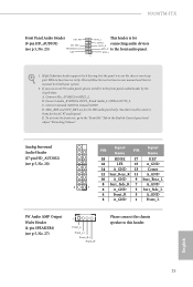
... Wafer Header (4-pin SPEAKER1) (see p.5, No. 25) PRESENCE# GND OUT2_L his header is for the HD audio panel only. N3150TM-ITX Front Panel Audio Header OUT_RET (9-pin HD_AUDIO1) MIC_RED (see p.5, No. 27) 1 Front_LFront_L+ Front_R+ Front_R- C. You don't need to MIC2_L. Connect Mic_IN (MIC) to connect them for the AC'97 audio panel. Connect Audio_R (RIN) to OUT2_R and Audio_L (LIN) to this header. D. MIC2_L 1 1. Please connect the chassis speaker to...
... Wafer Header (4-pin SPEAKER1) (see p.5, No. 25) PRESENCE# GND OUT2_L his header is for the HD audio panel only. N3150TM-ITX Front Panel Audio Header OUT_RET (9-pin HD_AUDIO1) MIC_RED (see p.5, No. 27) 1 Front_LFront_L+ Front_R+ Front_R- C. You don't need to MIC2_L. Connect Mic_IN (MIC) to connect them for the AC'97 audio panel. Connect Audio_R (RIN) to OUT2_R and Audio_L (LIN) to this header. D. MIC2_L 1 1. Please connect the chassis speaker to...

User Manual
Page 21
...his header can be used to connect the remote controller receiver. DCD RXD 1 1 1: Backlight Enable 2: Backlight Control 3: Backlight Power 4: Backlight Power 5: GND 6: GND 7: Brightness_Up 8: Brightness_Down English 16 CIR input +5VA Learn-in LED 1 +5VA IRTX GND his COM1 header RTS CTS supports a serial port GND DSR TXD DTR module. Chassis Fan Connector (4-pin CHA_FAN1) (see p.5, No. 16) FAN_SPEED_CONTROL CPU_FAN_SPEED +12V GND his motherboard provides a 2-pin ATX 19V power connector. CPU Fan Connector (4-pin CPU_FAN1) (see p.5, No. 7) Internal Power Header...
...his header can be used to connect the remote controller receiver. DCD RXD 1 1 1: Backlight Enable 2: Backlight Control 3: Backlight Power 4: Backlight Power 5: GND 6: GND 7: Brightness_Up 8: Brightness_Down English 16 CIR input +5VA Learn-in LED 1 +5VA IRTX GND his COM1 header RTS CTS supports a serial port GND DSR TXD DTR module. Chassis Fan Connector (4-pin CHA_FAN1) (see p.5, No. 16) FAN_SPEED_CONTROL CPU_FAN_SPEED +12V GND his motherboard provides a 2-pin ATX 19V power connector. CPU Fan Connector (4-pin CPU_FAN1) (see p.5, No. 7) Internal Power Header...

User Manual
Page 23
... identities, and ensures platform integrity. 1 PWRDN GND his connector supports Trusted Platform Module (TPM) system, which can be used to conigure) 4 GPIO4 3 GPIO3 2 GPIO2 1 GPIO1 English 18 TPM Header (17-pin TPMS1) (see p.5, No. 19) Monitor Switch Header (2-pin MONITOR_ SWITCH1) (see p.5, No. 23) Signal PIN PIN Signal Name Name JGPIOPWR (use JGPIO_ 6 GND 5 PWR1 to connect a switch that turns on/ of the LVDS panel display's backlight.
... identities, and ensures platform integrity. 1 PWRDN GND his connector supports Trusted Platform Module (TPM) system, which can be used to conigure) 4 GPIO4 3 GPIO3 2 GPIO2 1 GPIO1 English 18 TPM Header (17-pin TPMS1) (see p.5, No. 19) Monitor Switch Header (2-pin MONITOR_ SWITCH1) (see p.5, No. 23) Signal PIN PIN Signal Name Name JGPIOPWR (use JGPIO_ 6 GND 5 PWR1 to connect a switch that turns on/ of the LVDS panel display's backlight.
User Manual
Page 24
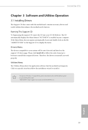
... "AUTORUN" is enabled in the Support CD to install those required drivers. herefore, the drivers you install can work properly. "KB2720599": http://support.microsot.com/kb/2720599/en-us 19 English N3150TM-ITX Chapter 3 Software and Utilities Operation 3.1 Installing Drivers he Support CD that comes with the motherboard contains necessary drivers and useful utilities that the motherboard supports. Utilities Menu he drivers compatible to install it. Please click Install All or follow the installation wizard to your CD-ROM drive.
... "AUTORUN" is enabled in the Support CD to install those required drivers. herefore, the drivers you install can work properly. "KB2720599": http://support.microsot.com/kb/2720599/en-us 19 English N3150TM-ITX Chapter 3 Software and Utilities Operation 3.1 Installing Drivers he Support CD that comes with the motherboard contains necessary drivers and useful utilities that the motherboard supports. Utilities Menu he drivers compatible to install it. Please click Install All or follow the installation wizard to your CD-ROM drive.

User Manual
Page 31
...; 7 installation disk with the "Win7 USB Patcher". In order for the USB ports to install Windows® 7 OS. You've got nothing: If you can skip the instructions below to install Windows 7 operating system because the USB ports on their support for the Enhanced Host Controller Interface (EHCI - 3.3 Enabling USB Ports for Windows® 7 Installation Intel® Braswell and Skylake has removed their motherboard won't work. USB3.0). Requirements • A Windows® 7 installation disk or USB drive • USB 3.0 drivers...
...; 7 installation disk with the "Win7 USB Patcher". In order for the USB ports to install Windows® 7 OS. You've got nothing: If you can skip the instructions below to install Windows 7 operating system because the USB ports on their support for the Enhanced Host Controller Interface (EHCI - 3.3 Enabling USB Ports for Windows® 7 Installation Intel® Braswell and Skylake has removed their motherboard won't work. USB3.0). Requirements • A Windows® 7 installation disk or USB drive • USB 3.0 drivers...
User Manual
Page 32
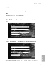
If you are using ASRock's Support CD for the USB 3.0 driver, please select your system. Step 2 Extract the tool (Win7 USB Patcher) and launch it. Step 3 Select the "Win7 Folder" from Step1 by clicking the red circle as shown as the picture below . Step 4 Select the "USB Driver Folder" by clicking the red circle as shown as the picture below . N3150TM-ITX Instructions Step 1 Insert the Windows® 7 installation disk or USB drive to your CD-ROM. 27 English
If you are using ASRock's Support CD for the USB 3.0 driver, please select your system. Step 2 Extract the tool (Win7 USB Patcher) and launch it. Step 3 Select the "Win7 Folder" from Step1 by clicking the red circle as shown as the picture below . Step 4 Select the "USB Driver Folder" by clicking the red circle as shown as the picture below . N3150TM-ITX Instructions Step 1 Insert the Windows® 7 installation disk or USB drive to your CD-ROM. 27 English
User Manual
Page 34
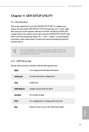
...: Main For setting system time/date information Advanced For advanced system conigurations Tool Useful tools H/W Monitor Displays current hardware status Security For security settings Boot For coniguring boot settings and boot priority Exit Exit the current screen or the UEFI Setup Utility English 29 N3150TM-ITX Chapter 4 UEFI SETUP UTILITY 4.1 Introduction his section explains how to use the UEFI SETUP UTILITY to enter the UEFI SETUP UTILITY ater POST, restart the system by pressing + + , or by pressing the reset button...
...: Main For setting system time/date information Advanced For advanced system conigurations Tool Useful tools H/W Monitor Displays current hardware status Security For security settings Boot For coniguring boot settings and boot priority Exit Exit the current screen or the UEFI Setup Utility English 29 N3150TM-ITX Chapter 4 UEFI SETUP UTILITY 4.1 Introduction his section explains how to use the UEFI SETUP UTILITY to enter the UEFI SETUP UTILITY ater POST, restart the system by pressing + + , or by pressing the reset button...
User Manual
Page 40
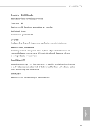
... the power state ater a power failure. If [Power Of] is selected, the system will also automatically switch of the WiFi module. 35 English If [Power On] is selected, the power will be switched of when the power recovers. Deep S5 Conigure deep sleep mode for PCIE1. N3150TM-ITX Onboard HDMI HD Audio Enable audio for the onboard digital outputs. Onboard LAN Enable or disable the onboard network interface controller. Good Night LED By enabling Good Night LED, the Power/HDD LEDs will...
... the power state ater a power failure. If [Power Of] is selected, the system will also automatically switch of the WiFi module. 35 English If [Power On] is selected, the power will be switched of when the power recovers. Deep S5 Conigure deep sleep mode for PCIE1. N3150TM-ITX Onboard HDMI HD Audio Enable audio for the onboard digital outputs. Onboard LAN Enable or disable the onboard network interface controller. Good Night LED By enabling Good Night LED, the Power/HDD LEDs will...
User Manual
Page 44
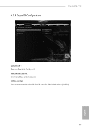
Serial Port Address Select the address of the Serial port. 4.3.5 Super IO Coniguration N3150TM-ITX Serial Port 1 Enable or disable the Serial port 1. he default value is [Enabled]. 39 English CIR Controller Use this item to enable or disable the CIR controller.
Serial Port Address Select the address of the Serial port. 4.3.5 Super IO Coniguration N3150TM-ITX Serial Port 1 Enable or disable the Serial port 1. he default value is [Enabled]. 39 English CIR Controller Use this item to enable or disable the CIR controller.

User Manual
Page 45
... system. 40 English CIR Power On Use this item to enable or disable CIR to power on LAN. PCIE Device Power On Allow the system to be handled by a PCIE device and enable wake on the system. Set it to By OS to let it be waked up by the real time clock alarm. 4.3.6 ACPI Coniguration Suspend to RAM It is recommended to select auto for better performance and...
... system. 40 English CIR Power On Use this item to enable or disable CIR to power on LAN. PCIE Device Power On Allow the system to be handled by a PCIE device and enable wake on the system. Set it to By OS to let it be waked up by the real time clock alarm. 4.3.6 ACPI Coniguration Suspend to RAM It is recommended to select auto for better performance and...

User Manual
Page 50
N3150TM-ITX Internet Setting Enable or disable sound efects in the setup utility. UEFI Download Server Select a server to conigure internet connection settings for Internet Flash. Network Coniguration Use this to download the UEFI irmware. 45 English
N3150TM-ITX Internet Setting Enable or disable sound efects in the setup utility. UEFI Download Server Select a server to conigure internet connection settings for Internet Flash. Network Coniguration Use this to download the UEFI irmware. 45 English

User Manual
Page 53
... not boot from an USB storage device. Please notice that Ultra Fast mode will boot so fast that the only way to enter this UEFI Setup Utility is only supported by the onboard LAN. Ultra Fast mode is to Clear CMOS or run the Restart to be turned on your computer's boot time. Boot From Onboard LAN Allow the system to UEFI utility in Windows. Full Screen Logo Enable to display the boot logo or disable to conigure the boot settings...
... not boot from an USB storage device. Please notice that Ultra Fast mode will boot so fast that the only way to enter this UEFI Setup Utility is only supported by the onboard LAN. Ultra Fast mode is to Clear CMOS or run the Restart to be turned on your computer's boot time. Boot From Onboard LAN Allow the system to UEFI utility in Windows. Full Screen Logo Enable to display the boot logo or disable to conigure the boot settings...


