

User Manual
Page 4
... 1 1.2 Speciications 2 1.3 Motherboard Layout 5 1.4 I/O Panel 7 Chapter 2 Installation 9 2.1 Installing Memory Modules (DIMM) 10 2.2 Expansion Slots (PCI Express Slots) 12 2.3 Jumpers Setup 13 2.4 Onboard Headers and Connectors 14 Chapter 3 Software and Utilities Operation 18 3.1 Installing Drivers 18 3.2 ASRock APP Shop 19 3.2.1 UI Overview 19 3.2.2 Apps 20 3.2.3 BIOS & Drivers 23 3.2.4 Setting 24 3.3 Creating Windows® 7 Installation Disk with USB 3.0 Drivers Packed 25 Chapter 4 UEFI SETUP UTILITY 29 4.1 Introduction 29 4.1.1 UEFI Menu Bar 29
... 1 1.2 Speciications 2 1.3 Motherboard Layout 5 1.4 I/O Panel 7 Chapter 2 Installation 9 2.1 Installing Memory Modules (DIMM) 10 2.2 Expansion Slots (PCI Express Slots) 12 2.3 Jumpers Setup 13 2.4 Onboard Headers and Connectors 14 Chapter 3 Software and Utilities Operation 18 3.1 Installing Drivers 18 3.2 ASRock APP Shop 19 3.2.1 UI Overview 19 3.2.2 Apps 20 3.2.3 BIOS & Drivers 23 3.2.4 Setting 24 3.3 Creating Windows® 7 Installation Disk with USB 3.0 Drivers Packed 25 Chapter 4 UEFI SETUP UTILITY 29 4.1 Introduction 29 4.1.1 UEFI Menu Bar 29
User Manual
Page 6
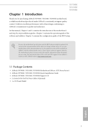
... the BIOS setup. ASRock website http://www.asrock.com. 1.1 Package Contents • ASRock N3700M / N3150M / N3050M Motherboard (Micro ATX Form Factor) • ASRock N3700M / N3150M / N3050M Quick Installation Guide • ASRock N3700M / N3150M / N3050M Support CD • 2 x Serial ATA (SATA) Data Cables (Optional) • 1 x I/O Panel Shield 1 English It delivers excellent performance with robust design conforming to ASRock's commitment to change without further notice. In case any modiications of the motherboard and step-by-step installation guides...
... the BIOS setup. ASRock website http://www.asrock.com. 1.1 Package Contents • ASRock N3700M / N3150M / N3050M Motherboard (Micro ATX Form Factor) • ASRock N3700M / N3150M / N3050M Quick Installation Guide • ASRock N3700M / N3150M / N3050M Support CD • 2 x Serial ATA (SATA) Data Cables (Optional) • 1 x I/O Panel Shield 1 English It delivers excellent performance with robust design conforming to ASRock's commitment to change without further notice. In case any modiications of the motherboard and step-by-step installation guides...
User Manual
Page 7
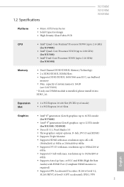
... 8) graphics: up to 12 EUs inside (for N3050M) Memory • Dual Channel DDR3/DDR3L Memory Technology • 2 x DDR3/DDR3L DIMM Slots • Supports DDR3/DDR3L 1600/1066 non-ECC, un-bufered memory • Max. resolution up to 4K x 2K (3840x2160) @ 30Hz or 2560x1600 @ 60Hz • Supports DVI-D with max. resolution up to 1920x1200 @ 60Hz • Supports Auto Lip Sync, xvYCC and HBR (High Bit Rate Audio) with HDMI Port...
... 8) graphics: up to 12 EUs inside (for N3050M) Memory • Dual Channel DDR3/DDR3L Memory Technology • 2 x DDR3/DDR3L DIMM Slots • Supports DDR3/DDR3L 1600/1066 non-ECC, un-bufered memory • Max. resolution up to 4K x 2K (3840x2160) @ 30Hz or 2560x1600 @ 60Hz • Supports DVI-D with max. resolution up to 1920x1200 @ 60Hz • Supports Auto Lip Sync, xvYCC and HBR (High Bit Rate Audio) with HDMI Port...

User Manual
Page 8
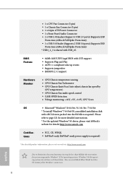
...x PS/2 Keyboard Port • 1 x D-Sub Port • 1 x DVI-D Port • 1 x HDMI Port • 2 x USB 2.0 Ports (Supports ESD Protection (ASRock Full Spike Protection)) • 2 x USB 3.0 Ports (Supports ESD Protection (ASRock Full Spike Protection)) • 1 x RJ-45 LAN Port with LED (ACT/LINK LED and SPEED LED) • HD Audio Jacks: Line in / Front Speaker / Microphone Storage • 2 x SATA3 6.0 Gb/s Connectors, support NCQ, AHCI and Hot Plug Connector • 1 x Print Port Header • 2 x COM Port Headers • 1 x TPM Header • 1 x Chassis Intrusion Header English...
...x PS/2 Keyboard Port • 1 x D-Sub Port • 1 x DVI-D Port • 1 x HDMI Port • 2 x USB 2.0 Ports (Supports ESD Protection (ASRock Full Spike Protection)) • 2 x USB 3.0 Ports (Supports ESD Protection (ASRock Full Spike Protection)) • 1 x RJ-45 LAN Port with LED (ACT/LINK LED and SPEED LED) • HD Audio Jacks: Line in / Front Speaker / Microphone Storage • 2 x SATA3 6.0 Gb/s Connectors, support NCQ, AHCI and Hot Plug Connector • 1 x Print Port Header • 2 x COM Port Headers • 1 x TPM Header • 1 x Chassis Intrusion Header English...

User Manual
Page 9
... To install Windows® 7 64-bit OS, a modiied installation disk with USB_45. Please refer to page 25 for more detailed instructions. * For the updated Windows® 10 driver, please visit ASRock's website for details: http://www.asrock.com Certiications • FCC, CE, WHQL • ErP/EuP ready (ErP/EuP ready power supply is required. N3700M N3150M N3050M • 1 x CPU Fan Connector (3-pin) • 1 x Chassis Fan Connector (3-pin) • 1 x 24 pin ATX Power Connector • 1 x Front Panel Audio Connector • 2 x USB 2.0 Headers (Support 4 USB 2.0 ports) (Supports...
... To install Windows® 7 64-bit OS, a modiied installation disk with USB_45. Please refer to page 25 for more detailed instructions. * For the updated Windows® 10 driver, please visit ASRock's website for details: http://www.asrock.com Certiications • FCC, CE, WHQL • ErP/EuP ready (ErP/EuP ready power supply is required. N3700M N3150M N3050M • 1 x CPU Fan Connector (3-pin) • 1 x Chassis Fan Connector (3-pin) • 1 x 24 pin ATX Power Connector • 1 x Front Panel Audio Connector • 2 x USB 2.0 Headers (Support 4 USB 2.0 ports) (Supports...

User Manual
Page 14
... static electricity to the motherboard's components, NEVER place your chassis to unplug the power cord before you install the motherboard, study the coniguration of the following precautions before installing or removing the motherboard. Chapter 2 Installation his is a Micro ATX form factor motherboard. Before you install motherboard components or change any components, place them on a carpet. Pre-installation Precautions Take note of your motherboard directly on a grounded...
... static electricity to the motherboard's components, NEVER place your chassis to unplug the power cord before you install the motherboard, study the coniguration of the following precautions before installing or removing the motherboard. Chapter 2 Installation his is a Micro ATX form factor motherboard. Before you install motherboard components or change any components, place them on a carpet. Pre-installation Precautions Take note of your motherboard directly on a grounded...
User Manual
Page 17
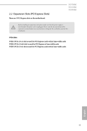
... the power supply is used for PCI Express cards with x1 lane width cards. 2.2 Expansion Slots (PCI Express Slots) here are 3 PCI Express slots on the motherboard. PCIe slots: PCIE1 (PCIe 2.0 x1 slot) is used for PCI Express cards with x1 lane width cards. Please read the documentation of or the power cord is used for the card before you start the installation. PCIE3 (PCIe 2.0 x1 slot) is unplugged. English 12 N3700M N3150M N3050M Before installing an expansion card, please make necessary hardware settings for PCI Express...
... the power supply is used for PCI Express cards with x1 lane width cards. 2.2 Expansion Slots (PCI Express Slots) here are 3 PCI Express slots on the motherboard. PCIe slots: PCIE1 (PCIe 2.0 x1 slot) is used for PCI Express cards with x1 lane width cards. Please read the documentation of or the power cord is used for the card before you start the installation. PCIE3 (PCIe 2.0 x1 slot) is unplugged. English 12 N3700M N3150M N3050M Before installing an expansion card, please make necessary hardware settings for PCI Express...
User Manual
Page 18
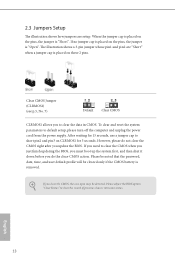
... CMOS right ater you update the BIOS. Clear CMOS Jumper (CLRMOS1) (see p.5, No. 7) Default Clear CMOS CLRMOS1 allows you clear the CMOS, the case open may be cleared only if the CMOS battery is "Short". Please be noted that the password, date, time, and user default proile will be detected. When the jumper cap is placed on the pins, the jumper is removed. English 13 If no jumper cap is placed on the pins, the jumper...
... CMOS right ater you update the BIOS. Clear CMOS Jumper (CLRMOS1) (see p.5, No. 7) Default Clear CMOS CLRMOS1 allows you clear the CMOS, the case open may be cleared only if the CMOS battery is "Short". Please be noted that the password, date, time, and user default proile will be detected. When the jumper cap is placed on the pins, the jumper is removed. English 13 If no jumper cap is placed on the pins, the jumper...

User Manual
Page 19
... connectors. System Panel Header (9-pin PANEL1) (see p.5, No. 9) PLED+ PLEDPWRBTN# GND 1 GND RESET# GND HDLEDHDLED+ Connect the power switch, reset switch and system status indicator on when the system is reading or writing data. You may difer by chassis. HDLED (Hard Drive Activity LED): Connect to the pin assignments below. A front panel module mainly consists of your chassis front panel module to the reset switch on the chassis front panel. When connecting your system using the power switch...
... connectors. System Panel Header (9-pin PANEL1) (see p.5, No. 9) PLED+ PLEDPWRBTN# GND 1 GND RESET# GND HDLEDHDLED+ Connect the power switch, reset switch and system status indicator on when the system is reading or writing data. You may difer by chassis. HDLED (Hard Drive Activity LED): Connect to the pin assignments below. A front panel module mainly consists of your chassis front panel module to the reset switch on the chassis front panel. When connecting your system using the power switch...
User Manual
Page 21
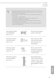
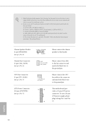
... his motherboard provides a 24-pin ATX power connector. You don't need to this header. Chassis Speaker Header (4-pin SPEAKER1) (see p.5, No. 8) Chassis Fan Connector (3-pin CHA_FAN1) (see p.5, No. 6) CPU Fan Connector (3-pin CPU_FAN1) (see p.5, No. 3) ATX Power Connector (24-pin ATXPWR1) (see p.5, No. 5) DUMMY SPEAKER 1 +5V DUMMY Please connect the chassis speaker to connect them for the HD audio panel only. To use an AC'97 audio panel, please install it along Pin 1 and Pin 13. If you use a 20-pin ATX power supply, please plug it to Ground (GND). E. Connect Ground...
... his motherboard provides a 24-pin ATX power connector. You don't need to this header. Chassis Speaker Header (4-pin SPEAKER1) (see p.5, No. 8) Chassis Fan Connector (3-pin CHA_FAN1) (see p.5, No. 6) CPU Fan Connector (3-pin CPU_FAN1) (see p.5, No. 3) ATX Power Connector (24-pin ATXPWR1) (see p.5, No. 5) DUMMY SPEAKER 1 +5V DUMMY Please connect the chassis speaker to connect them for the HD audio panel only. To use an AC'97 audio panel, please install it along Pin 1 and Pin 13. If you use a 20-pin ATX power supply, please plug it to Ground (GND). E. Connect Ground...
User Manual
Page 23
... drivers compatible to install it. Click on the support CD driver page. he CD automatically displays the Main Menu if "AUTORUN" is enabled in the Support CD to install those required drivers. herefore, the drivers you install can work properly. Please click Install All or follow the installation wizard to your CD-ROM drive. Chapter 3 Software and Utilities Operation 3.1 Installing Drivers he Support CD that comes with the motherboard contains necessary drivers and useful utilities that the motherboard supports. Utilities Menu he Utilities Menu...
... drivers compatible to install it. Click on the support CD driver page. he CD automatically displays the Main Menu if "AUTORUN" is enabled in the Support CD to install those required drivers. herefore, the drivers you install can work properly. Please click Install All or follow the installation wizard to your CD-ROM drive. Chapter 3 Software and Utilities Operation 3.1 Installing Drivers he Support CD that comes with the motherboard contains necessary drivers and useful utilities that the motherboard supports. Utilities Menu he Utilities Menu...
User Manual
Page 30
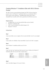
...; 7 installation disk in the ASRock Support CD) • Windows® 7 64-bit PC Instructions Step 1 Create a new folder on your motherboard require the USB 3.0 drivers to function properly. Name the subfolder "mount" and "usb3" as an example. Step 4 Copy "boot.wim" and "install.wim" iles from the "Sources" folder in the Windows® 7 installation disk to the Windows® 7 installation disk does not include the USB 3.0 drivers, please create a Windows® 7 installation disk...
...; 7 installation disk in the ASRock Support CD) • Windows® 7 64-bit PC Instructions Step 1 Create a new folder on your motherboard require the USB 3.0 drivers to function properly. Name the subfolder "mount" and "usb3" as an example. Step 4 Copy "boot.wim" and "install.wim" iles from the "Sources" folder in the Windows® 7 installation disk to the Windows® 7 installation disk does not include the USB 3.0 drivers, please create a Windows® 7 installation disk...
User Manual
Page 34
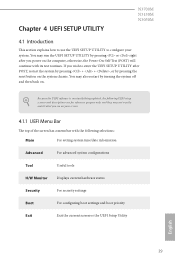
... Advanced For advanced system conigurations Tool Useful tools H/W Monitor Displays current hardware status Security For security settings Boot For coniguring boot settings and boot priority Exit Exit the current screen or the UEFI Setup Utility English 29 Chapter 4 UEFI SETUP UTILITY N3700M N3150M N3050M 4.1 Introduction his section explains how to use the UEFI SETUP UTILITY to enter the UEFI SETUP UTILITY ater POST, restart the system by pressing + + , or by pressing the reset button on your system.
... Advanced For advanced system conigurations Tool Useful tools H/W Monitor Displays current hardware status Security For security settings Boot For coniguring boot settings and boot priority Exit Exit the current screen or the UEFI Setup Utility English 29 Chapter 4 UEFI SETUP UTILITY N3700M N3150M N3050M 4.1 Introduction his section explains how to use the UEFI SETUP UTILITY to enter the UEFI SETUP UTILITY ater POST, restart the system by pressing + + , or by pressing the reset button on your system.

User Manual
Page 40
he default value is installed. Front Panel Enable/disable front panel HD audio. Onboard HDMI HD Audio Enable audio for the onboard digital outputs. Onboard HD Audio Enable/disable onboard HD audio. Share Memory Conigure the size of memory that is allocated to conigure DRAM Voltage. 4.3.2 Chipset Coniguration N3700M N3150M N3050M DRAM Voltage Use this to the integrated graphics processor when the system boots up. Onboard LAN Enable or disable the onboard network interface controller. 35 English Primary Graphics Adapter Select a primary VGA. Set to Auto to enable onboard HD...
he default value is installed. Front Panel Enable/disable front panel HD audio. Onboard HDMI HD Audio Enable audio for the onboard digital outputs. Onboard HD Audio Enable/disable onboard HD audio. Share Memory Conigure the size of memory that is allocated to conigure DRAM Voltage. 4.3.2 Chipset Coniguration N3700M N3150M N3050M DRAM Voltage Use this to the integrated graphics processor when the system boots up. Onboard LAN Enable or disable the onboard network interface controller. 35 English Primary Graphics Adapter Select a primary VGA. Set to Auto to enable onboard HD...

User Manual
Page 50
N3700M N3150M N3050M Internet Setting Enable or disable sound efects in the setup utility. Network Coniguration Use this to download the UEFI irmware. 45 English UEFI Download Server Select a server to conigure internet connection settings for Internet Flash.
N3700M N3150M N3050M Internet Setting Enable or disable sound efects in the setup utility. Network Coniguration Use this to download the UEFI irmware. 45 English UEFI Download Server Select a server to conigure internet connection settings for Internet Flash.
User Manual
Page 51
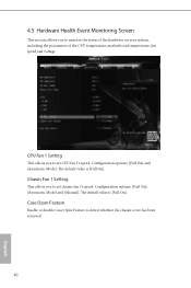
... default value is [Full On]. he default value is [Full On]. CPU Fan 1 Setting his allows you to set chassis fan 1's speed. Chassis Fan 1 Setting his allows you to set CPU fan 1's speed. Coniguration options: [Full On], [Automatic Mode] and [Manual]. Case Open Feature Enable or disable Case Open Feature to monitor the status of the hardware on your system, including the parameters of the CPU temperature, motherboard temperature, fan speed and voltage. Coniguration options: [Full On] and [Automatic Mode]. 4.5 Hardware Health Event Monitoring Screen...
... default value is [Full On]. he default value is [Full On]. CPU Fan 1 Setting his allows you to set chassis fan 1's speed. Chassis Fan 1 Setting his allows you to set CPU fan 1's speed. Coniguration options: [Full On], [Automatic Mode] and [Manual]. Case Open Feature Enable or disable Case Open Feature to monitor the status of the hardware on your system, including the parameters of the CPU temperature, motherboard temperature, fan speed and voltage. Coniguration options: [Full On] and [Automatic Mode]. 4.5 Hardware Health Event Monitoring Screen...
Quick Installation Guide
Page 10
... ready power supply is shared with xHCI drivers packed into the ISO ile is required. Please refer to utilize the memory that Windows® cannot use. 8 BIOS Feature • 64Mb AMI UEFI Legal BIOS with GUI support • Supports Plug and Play • ACPI 1.1 compliant wake up events • Supports jumperfree • SMBIOS 2.3.1 support Hardware Monitor • CPU/Chassis temperature sensing • CPU/Chassis Fan Tachometer • CPU/Chassis Quiet Fan (Auto adjust chassis fan speed by CPU temperature) • CPU/Chassis Fan multi-speed control • CASE OPEN...
... ready power supply is shared with xHCI drivers packed into the ISO ile is required. Please refer to utilize the memory that Windows® cannot use. 8 BIOS Feature • 64Mb AMI UEFI Legal BIOS with GUI support • Supports Plug and Play • ACPI 1.1 compliant wake up events • Supports jumperfree • SMBIOS 2.3.1 support Hardware Monitor • CPU/Chassis temperature sensing • CPU/Chassis Fan Tachometer • CPU/Chassis Quiet Fan (Auto adjust chassis fan speed by CPU temperature) • CPU/Chassis Fan multi-speed control • CASE OPEN...
Quick Installation Guide
Page 15
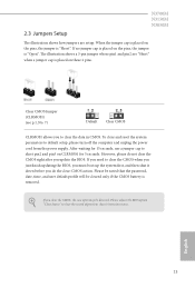
...". Please adjust the BIOS option "Clear Status" to default setup, please turn of previous chassis intrusion status. However, please do the clear-CMOS action. N3700M N3150M N3050M 2.3 Jumpers Setup he illustration shows a 3-pin jumper whose pin1 and pin2 are setup. he illustration shows how jumpers are "Short" when a jumper cap is placed on the pins, the jumper is placed on these 2 pins. To clear and reset the system parameters to clear the record of...
...". Please adjust the BIOS option "Clear Status" to default setup, please turn of previous chassis intrusion status. However, please do the clear-CMOS action. N3700M N3150M N3050M 2.3 Jumpers Setup he illustration shows a 3-pin jumper whose pin1 and pin2 are setup. he illustration shows how jumpers are "Short" when a jumper cap is placed on the pins, the jumper is placed on these 2 pins. To clear and reset the system parameters to clear the record of...
Quick Installation Guide
Page 18
... the panel wire on the chassis must support HDA to OUT2_L. If you use a 20-pin ATX power supply, please plug it to install your system. 2. To activate the front mic, go to the "FrontMic" Tab in our manual and chassis manual to the front panel audio header by the steps below: A. To use an AC'97 audio panel, please install it along Pin 1 and Pin 13. Please follow the instructions in the Realtek Control panel...
... the panel wire on the chassis must support HDA to OUT2_L. If you use a 20-pin ATX power supply, please plug it to install your system. 2. To activate the front mic, go to the "FrontMic" Tab in our manual and chassis manual to the front panel audio header by the steps below: A. To use an AC'97 audio panel, please install it along Pin 1 and Pin 13. Please follow the instructions in the Realtek Control panel...
Quick Installation Guide
Page 123
...; Windows® 7 installation disk • USB 3.0 drivers (included in the Windows® 7 installation disk to the Windows® 7 installation disk does not include the USB 3.0 drivers, please create a Windows® 7 installation disk with USB 3.0 Drivers Packed he USB 3.0 ports on your CD drive. 121 English Step 4 Copy "boot.wim" and "install.wim" iles from the "Sources" folder in the ASRock Support CD) • Windows® 7 64-bit PC Instructions Step 1 Create a new folder on your motherboard require the USB 3.0 drivers to...
...; Windows® 7 installation disk • USB 3.0 drivers (included in the Windows® 7 installation disk to the Windows® 7 installation disk does not include the USB 3.0 drivers, please create a Windows® 7 installation disk with USB 3.0 Drivers Packed he USB 3.0 ports on your CD drive. 121 English Step 4 Copy "boot.wim" and "install.wim" iles from the "Sources" folder in the ASRock Support CD) • Windows® 7 64-bit PC Instructions Step 1 Create a new folder on your motherboard require the USB 3.0 drivers to...


