User Manual
Page 3
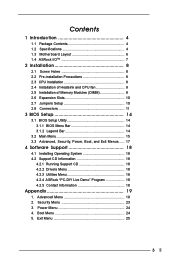
... Contents 1 Introduction 4 1.1 Package Contents 4 1.2 Specifications 4 1.3 Motherboard Layout 6 1.4 ASRock I/OTM 7 2 Installation 8 2.1 Screw Holes 8 2.2 Pre-installation Precautions 8 2.3 CPU Installation 8 2.4 Installation of Heatsink and CPU fan 9 2.5 Installation of Memory Modules (DIMM 9 2.6 Expansion Slots 10 2.7 Jumpers Setup...Boot, and Exit Menus ..... 17 4 Software Support 18 4.1 Installing Operating System 18 4.2 Support CD Information 18 4.2.1 Running Support CD 18 4.2.2 Drivers Menu 18 4.2.3 Utilities Menu 18 4.2.4 ASRock "PC-DIY Live Demo" Program 18 4.2.5 ...
... Contents 1 Introduction 4 1.1 Package Contents 4 1.2 Specifications 4 1.3 Motherboard Layout 6 1.4 ASRock I/OTM 7 2 Installation 8 2.1 Screw Holes 8 2.2 Pre-installation Precautions 8 2.3 CPU Installation 8 2.4 Installation of Heatsink and CPU fan 9 2.5 Installation of Memory Modules (DIMM 9 2.6 Expansion Slots 10 2.7 Jumpers Setup...Boot, and Exit Menus ..... 17 4 Software Support 18 4.1 Installing Operating System 18 4.2 Support CD Information 18 4.2.1 Running Support CD 18 4.2.2 Drivers Menu 18 4.2.3 Utilities Menu 18 4.2.4 ASRock "PC-DIY Live Demo" Program 18 4.2.5 ...

User Manual
Page 4
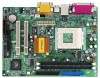
... to change without further notice. ASRock website http://www.asrock.com 1.1 Package Contents ASRock M810LMR motherboard (Micro ATX form factor: 9.6" x 7.0", 24.4 x 17.8 cm) ASRock M810LMR Quick Installation Guide ASRock AMD-VIA Series Support CD 1 cable for IDE devices (1 x ATA 66/100) 1 cable for floppy drive (1 x ribbon cable) 1 ASRock I/O shield 1 COM port bracket 1.2 Specifications Platform: CPU: Chipsets: Clock Generator: Memory: IDE...
... to change without further notice. ASRock website http://www.asrock.com 1.1 Package Contents ASRock M810LMR motherboard (Micro ATX form factor: 9.6" x 7.0", 24.4 x 17.8 cm) ASRock M810LMR Quick Installation Guide ASRock AMD-VIA Series Support CD 1 cable for IDE devices (1 x ATA 66/100) 1 cable for floppy drive (1 x ribbon cable) 1 ASRock I/O shield 1 COM port bracket 1.2 Specifications Platform: CPU: Chipsets: Clock Generator: Memory: IDE...

User Manual
Page 5
...Although M810LMR offers stepless control, it is not recommended to spray thermal grease between the CPU and the heatsink when you resume the system. Voltage monitoring: +12V, +5V, +3V, +2.5V, Vcore; Supports jumperfree; When the CPU frequency of the system or damage the CPU ...with PCI Specification 2.1 1 slot, supports ASRock MR card (optional) PS/2: 1 keyboard port / 1 mouse port; 1 RJ 45 port; 4 rear default USB 1.1 ports (see CAUTION 1); Please check if the CPU fan on page 7); 1 VGA port; 1 parallel port: ECP/EPP support; CPU overheat shutdown to perform over clocking. ...
...Although M810LMR offers stepless control, it is not recommended to spray thermal grease between the CPU and the heatsink when you resume the system. Voltage monitoring: +12V, +5V, +3V, +2.5V, Vcore; Supports jumperfree; When the CPU frequency of the system or damage the CPU ...with PCI Specification 2.1 1 slot, supports ASRock MR card (optional) PS/2: 1 keyboard port / 1 mouse port; 1 RJ 45 port; 4 rear default USB 1.1 ports (see CAUTION 1); Please check if the CPU fan on page 7); 1 VGA port; 1 parallel port: ECP/EPP support; CPU overheat shutdown to perform over clocking. ...

User Manual
Page 12
...(9-pin AUDIO1) (see p.6 item 23) IRTX +5V DUMMY 1 GND IRRX AUX-L GND GND AUX-R AUX1 CD-L GND GND CD-R CD1 This connector supports an optional wireless transmitting and receiving infrared module. O U T- This connector allows you to receive stereo audio input from sound sources such as a CD-ROM... ground pin. R MIC-POWER MIC This is an interface for front panel audio cable that allows convenient connection and control of audio devices. CPU fan connector (3-pin CPU_FAN1) (see p.6 item 9) GND +12V CHA_FAN_SPEED Connect the fan cable to the connector matching the black wire to the...
...(9-pin AUDIO1) (see p.6 item 23) IRTX +5V DUMMY 1 GND IRRX AUX-L GND GND AUX-R AUX1 CD-L GND GND CD-R CD1 This connector supports an optional wireless transmitting and receiving infrared module. O U T- This connector allows you to receive stereo audio input from sound sources such as a CD-ROM... ground pin. R MIC-POWER MIC This is an interface for front panel audio cable that allows convenient connection and control of audio devices. CPU fan connector (3-pin CPU_FAN1) (see p.6 item 9) GND +12V CHA_FAN_SPEED Connect the fan cable to the connector matching the black wire to the...

User Manual
Page 20
... [ Setup Help ] PCI Delay Transaction OnChip VGA Frame Buffer Size USB Controller USB Device Legacy Support SDRAM CAS Latency Disabled Auto Enabled Disabled Auto [Enabled] to free the PCI bus when the CPU is used to set the size of the share memory for the onboard VGA will auto-detect... USB controller. If the graphics card is detected, the onboard VGA will free the PCI Bus when the CPU is inserted. USB Device Legacy Support: Use this to enable or disable the support to enable or disable the use of memory accessing. 20 USB Controller: Use this feature when using ISA ...
... [ Setup Help ] PCI Delay Transaction OnChip VGA Frame Buffer Size USB Controller USB Device Legacy Support SDRAM CAS Latency Disabled Auto Enabled Disabled Auto [Enabled] to free the PCI bus when the CPU is used to set the size of the share memory for the onboard VGA will auto-detect... USB controller. If the graphics card is detected, the onboard VGA will free the PCI Bus when the CPU is inserted. USB Device Legacy Support: Use this to enable or disable the support to enable or disable the use of memory accessing. 20 USB Controller: Use this feature when using ISA ...


