User Manual
Page 3
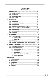
...5. Contents 1 Introduction 4 1.1 Package Contents 4 1.2 Specifications 4 1.3 Motherboard Layout 6 1.4 ASRock I/OTM 7 2 Installation 8 2.1 Screw Holes 8 2.2 Pre-installation Precautions 8 2.3 CPU Installation 8 2.4 Installation of Heatsink and CPU fan 9 2.5 Installation of Memory Modules (DIMM 9 2.6 Expansion Slots 10 2.7 Jumpers Setup ...18 4.2 Support CD Information 18 4.2.1 Running Support CD 18 4.2.2 Drivers Menu 18 4.2.3 Utilities Menu 18 4.2.4 ASRock "PC-DIY Live Demo" Program 18 4.2.5 Contact Information 18 Appendix 19 1. Advanced Menu 19 2. Exit Menu 25 3 ...
...5. Contents 1 Introduction 4 1.1 Package Contents 4 1.2 Specifications 4 1.3 Motherboard Layout 6 1.4 ASRock I/OTM 7 2 Installation 8 2.1 Screw Holes 8 2.2 Pre-installation Precautions 8 2.3 CPU Installation 8 2.4 Installation of Heatsink and CPU fan 9 2.5 Installation of Memory Modules (DIMM 9 2.6 Expansion Slots 10 2.7 Jumpers Setup ...18 4.2 Support CD Information 18 4.2.1 Running Support CD 18 4.2.2 Drivers Menu 18 4.2.3 Utilities Menu 18 4.2.4 ASRock "PC-DIY Live Demo" Program 18 4.2.5 Contact Information 18 Appendix 19 1. Advanced Menu 19 2. Exit Menu 25 3 ...

User Manual
Page 4
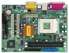
... devices Supports floppy disk drive 4 ASRock website http://www.asrock.com 1.1 Package Contents ASRock M810LMR motherboard (Micro ATX form factor: 9.6" x 7.0", 24.4 x 17.8 cm) ASRock M810LMR Quick Installation Guide ASRock AMD-VIA Series Support CD 1 cable for IDE devices (1 x ATA 66/100) 1 cable for floppy drive (1 x ribbon cable) 1 ASRock I/O shield 1 COM port bracket 1.2 Specifications Platform: CPU: Chipsets: Clock Generator: Memory...
... devices Supports floppy disk drive 4 ASRock website http://www.asrock.com 1.1 Package Contents ASRock M810LMR motherboard (Micro ATX form factor: 9.6" x 7.0", 24.4 x 17.8 cm) ASRock M810LMR Quick Installation Guide ASRock AMD-VIA Series Support CD 1 cable for IDE devices (1 x ATA 66/100) 1 cable for floppy drive (1 x ribbon cable) 1 ASRock I/O shield 1 COM port bracket 1.2 Specifications Platform: CPU: Chipsets: Clock Generator: Memory...

User Manual
Page 5
...to perform over clocking, other than the recommended CPU bus frequencies may cause the instability of M810LMR is detected, the system will also be overclocked proportionally. When the CPU frequency of the system or damage the CPU and the motherboard. 5 Supports jumperfree; SMBIOS ... the motherboard functions properly before you install the PC system. 2. While CPU overheat is set to protect CPU life (ASRock U-COP) (see CAUTION 2) Microsoft® Windows® 98 SE / ME / 2000 / XP compliant CAUTION! 1. CPU overheat shutdown to perform over clocking. Voltage monitoring: +12V, +5V,...
...to perform over clocking, other than the recommended CPU bus frequencies may cause the instability of M810LMR is detected, the system will also be overclocked proportionally. When the CPU frequency of the system or damage the CPU and the motherboard. 5 Supports jumperfree; SMBIOS ... the motherboard functions properly before you install the PC system. 2. While CPU overheat is set to protect CPU life (ASRock U-COP) (see CAUTION 2) Microsoft® Windows® 98 SE / ME / 2000 / XP compliant CAUTION! 1. CPU overheat shutdown to perform over clocking. Voltage monitoring: +12V, +5V,...

User Manual
Page 9
Unlock the socket by pressing the retaining clips outward. Step 3. DO NOT force the CPU into the socket to the instruction manuals of vendors of CPU fan and heatsink. 2.5 Installation of Memory Modules (DIMM) M810LMR motherboard provides two 168-pin SDRAM DIMM slots. For proper installation, please kindly refer to avoid bending of 600...
Unlock the socket by pressing the retaining clips outward. Step 3. DO NOT force the CPU into the socket to the instruction manuals of vendors of CPU fan and heatsink. 2.5 Installation of Memory Modules (DIMM) M810LMR motherboard provides two 168-pin SDRAM DIMM slots. For proper installation, please kindly refer to avoid bending of 600...

User Manual
Page 10
...jumper is by means of the adjustment of jumper-setting. If no jumper cap is placed on M810LMR motherboard. 2.6 Expansion Slots (PCI and AMR Slots) There are setup. AMR slot: AMR ...bit PCI interface. The illustration shows a 3-pin jumper whose pin1 and pin2 are used to insert ASRock MR card with v.92 Modem functionality. Step 3. Step 5. Step 6. Before installing the expansion card... item 26) Setting 2_3 FSB_SEL1 FSB 100MHz 1_2 FSB_SEL1 FSB 133MHz Note: The setting of the CPU front side bus frequency of the expansion card and make necessary hardware settings for later use . ...
...jumper is by means of the adjustment of jumper-setting. If no jumper cap is placed on M810LMR motherboard. 2.6 Expansion Slots (PCI and AMR Slots) There are setup. AMR slot: AMR ...bit PCI interface. The illustration shows a 3-pin jumper whose pin1 and pin2 are used to insert ASRock MR card with v.92 Modem functionality. Step 3. Step 5. Step 6. Before installing the expansion card... item 26) Setting 2_3 FSB_SEL1 FSB 100MHz 1_2 FSB_SEL1 FSB 133MHz Note: The setting of the CPU front side bus frequency of the expansion card and make necessary hardware settings for later use . ...

User Manual
Page 12
... audio input from sound sources such as a CD-ROM, DVD-ROM, TV tuner card, or MPEG card. O U T- This connector allows you to the ground pin. CPU fan connector (3-pin CPU_FAN1) (see p.6 item 3) GND +12V CPU_FAN_SPEED Connect the fan cable to the connector matching the black wire to the secondary IDE connector...
... audio input from sound sources such as a CD-ROM, DVD-ROM, TV tuner card, or MPEG card. O U T- This connector allows you to the ground pin. CPU fan connector (3-pin CPU_FAN1) (see p.6 item 3) GND +12V CPU_FAN_SPEED Connect the fan cable to the connector matching the black wire to the secondary IDE connector...

User Manual
Page 19
...introduce you the following BIOS Setup menus: "Advanced," "Security," "Power," "Boot," and "Exit." 1. VERSION 3.31a Security Power Boot Exit Spread Spectrum CPU Host Frequency Actual Frequency SDRAM Frequency Disabled By Jumper 133MHz Auto [ Setup Help ] to [Auto], the motherboard detects the memory module(s) inserted and automatically... frequency. Advanced BIOS Setup Menu Main Advanced AMIBIOS SETUP UTILITY - Appendix: Advanced BIOS Setup This section will let the CPU host frequency of spread spectrum.. You may cause problems during operation. SDRAM Frequency: If set...
...introduce you the following BIOS Setup menus: "Advanced," "Security," "Power," "Boot," and "Exit." 1. VERSION 3.31a Security Power Boot Exit Spread Spectrum CPU Host Frequency Actual Frequency SDRAM Frequency Disabled By Jumper 133MHz Auto [ Setup Help ] to [Auto], the motherboard detects the memory module(s) inserted and automatically... frequency. Advanced BIOS Setup Menu Main Advanced AMIBIOS SETUP UTILITY - Appendix: Advanced BIOS Setup This section will let the CPU host frequency of spread spectrum.. You may cause problems during operation. SDRAM Frequency: If set...

User Manual
Page 20
... Frame Buffer Size USB Controller USB Device Legacy Support SDRAM CAS Latency Disabled Auto Enabled Disabled Auto [Enabled] to free the PCI bus when the CPU is detected, the onboard VGA will not share the system memory. USB Device Legacy Support: Use this to enable or disable the support to adjust... Size: This allows you to enable or disable the use of the share memory for the onboard VGA will free the PCI Bus when the CPU is used to emulate legacy I/O devices such as 32MB. SDRAM CAS Latency: This is accessing 8-bit ISA cards. If no graphics card is inserted. When...
... Frame Buffer Size USB Controller USB Device Legacy Support SDRAM CAS Latency Disabled Auto Enabled Disabled Auto [Enabled] to free the PCI bus when the CPU is detected, the onboard VGA will not share the system memory. USB Device Legacy Support: Use this to enable or disable the support to adjust... Size: This allows you to enable or disable the use of the share memory for the onboard VGA will free the PCI Bus when the CPU is used to emulate legacy I/O devices such as 32MB. SDRAM CAS Latency: This is accessing 8-bit ISA cards. If no graphics card is inserted. When...

User Manual
Page 22
... OnBoard Midi Port feature. Parallel Port Mode: Set the operation mode of the hardware on your system. VERSION 3.31a System Hardware Monitor [ Setup Help ] CPU Temperature M / B Temperature CPU Fan Speed Chassis Fan Speed Vcore + 2.500V + 3.300V + 5.000V + 12.000V 45 C / 113 F 27 C / 82 F 3110 RPM 0 RPM 1....Save & Exit 22 Configuration options: [Auto], [Disabled], [378], [278]. MIDI Port I/O Address: Select I/O address for CPU temperature, Motherboard temperature, CPU fan speed, and critical voltage. OnBoard LAN: This allows you to enable or disable the OnBoard LAN feature.
... OnBoard Midi Port feature. Parallel Port Mode: Set the operation mode of the hardware on your system. VERSION 3.31a System Hardware Monitor [ Setup Help ] CPU Temperature M / B Temperature CPU Fan Speed Chassis Fan Speed Vcore + 2.500V + 3.300V + 5.000V + 12.000V 45 C / 113 F 27 C / 82 F 3110 RPM 0 RPM 1....Save & Exit 22 Configuration options: [Auto], [Disabled], [378], [278]. MIDI Port I/O Address: Select I/O address for CPU temperature, Motherboard temperature, CPU fan speed, and critical voltage. OnBoard LAN: This allows you to enable or disable the OnBoard LAN feature.


