User Manual
Page 4
... 77 4.1 Install Operating System 77 4.2 Support CD Information 77 4.2.1 Running Support CD 77 4.2.2 Drivers Menu 77 4.2.3 Utilities Menu 77 4.2.4 Contact Information 77 4 BIOS SETUP UTILITY 54 3.1 Introduction 54 3.1.1 BIOS Menu Bar 54 3.1.2 Navigation Keys 55 3.2 Main Screen 55 3.3 Smart Screen 56 3.4 Advanced Screen 57 3.4.1 CPU Configuration 58 3.4.2 Memory Configuration 60 3.4.3 Chipset Configuration...
... 77 4.1 Install Operating System 77 4.2 Support CD Information 77 4.2.1 Running Support CD 77 4.2.2 Drivers Menu 77 4.2.3 Utilities Menu 77 4.2.4 Contact Information 77 4 BIOS SETUP UTILITY 54 3.1 Introduction 54 3.1.1 BIOS Menu Bar 54 3.1.2 Navigation Keys 55 3.2 Main Screen 55 3.3 Smart Screen 56 3.4 Advanced Screen 57 3.4.1 CPU Configuration 58 3.4.2 Memory Configuration 60 3.4.3 Chipset Configuration...

User Manual
Page 5
... 1 x ASRock M3A780GXH/128M Motherboard (ATX Form Factor: 12.0-in x 8.8-in, 30.5 cm x 22.4 cm) 1 x ASRock M3A780GXH/128M Quick Installation Guide 2 x ASRock M3A780GXH/128M Support CD 1 x Ultra ATA 66/100/133 IDE Ribbon Cable (80-conductor) 1 x Ribbon Cable for purchasing ASRock M3A780GXH/128M motherboard, a reliable motherboard produced under ASRock's consistently stringent quality control. It delivers excellent performance with robust design conforming to ASRock's commitment to BIOS...
... 1 x ASRock M3A780GXH/128M Motherboard (ATX Form Factor: 12.0-in x 8.8-in, 30.5 cm x 22.4 cm) 1 x ASRock M3A780GXH/128M Quick Installation Guide 2 x ASRock M3A780GXH/128M Support CD 1 x Ultra ATA 66/100/133 IDE Ribbon Cable (80-conductor) 1 x Ribbon Cable for purchasing ASRock M3A780GXH/128M motherboard, a reliable motherboard produced under ASRock's consistently stringent quality control. It delivers excellent performance with robust design conforming to ASRock's commitment to BIOS...

User Manual
Page 7
... - CPU/Chassis/NB/Power FAN connector - 24 pin ATX power connector - 8 pin 12V power connector - SLI/XFIRE power connector - Supports Smart BIOS - AMI Legal BIOS - Front panel audio connector - 3 x USB 2.0 headers (support 6 USB 2.0 ports) (see CAUTION 10) - 1 x ATA133 IDE connector ...x COM port header - 1 x IEEE 1394 header - 1 x HDMI_SPDIF header - HD Audio Jack: Side Speaker/Rear Speaker/Central/Bass/ Line in header - Rear Panel I/O Connector BIOS Feature Support CD I/O Panel - 1 x PS/2 Keyboard Port - 1 x VGA/D-Sub Port - 1 x VGA/DVI-D Port - 1 x HDMI Port - 1 x Optical SPDIF...
... - CPU/Chassis/NB/Power FAN connector - 24 pin ATX power connector - 8 pin 12V power connector - SLI/XFIRE power connector - Supports Smart BIOS - AMI Legal BIOS - Front panel audio connector - 3 x USB 2.0 headers (support 6 USB 2.0 ports) (see CAUTION 10) - 1 x ATA133 IDE connector ...x COM port header - 1 x IEEE 1394 header - 1 x HDMI_SPDIF header - HD Audio Jack: Side Speaker/Rear Speaker/Central/Bass/ Line in header - Rear Panel I/O Connector BIOS Feature Support CD I/O Panel - 1 x PS/2 Keyboard Port - 1 x VGA/D-Sub Port - 1 x VGA/DVI-D Port - 1 x HDMI Port - 1 x Optical SPDIF...
User Manual
Page 8
...! 1. For Windows® XP 64-bit and Windows® VistaTM 64bit with overclocking, including adjusting the setting in the BIOS, applying Untied Overclocking Technology, or using the thirdparty overclocking tools. Unique Feature - CPU Frequency Stepless Control (see CAUTION 12)... - Chassis Temperature Sensing - This motherboard supports Untied Overclocking Technology. This motherboard supports Dual Channel Memory Technology. ASRock website http://www.asrock.com 4. ASRock OC Tuner (see CAUTION 14) - Please read the installation guide of your own risk and expense. CPU...
...! 1. For Windows® XP 64-bit and Windows® VistaTM 64bit with overclocking, including adjusting the setting in the BIOS, applying Untied Overclocking Technology, or using the thirdparty overclocking tools. Unique Feature - CPU Frequency Stepless Control (see CAUTION 12)... - Chassis Temperature Sensing - This motherboard supports Untied Overclocking Technology. This motherboard supports Dual Channel Memory Technology. ASRock website http://www.asrock.com 4. ASRock OC Tuner (see CAUTION 14) - Please read the installation guide of your own risk and expense. CPU...
User Manual
Page 9
...ray (BD) / HD-DVD playback support on this motherboard offers stepless control, it is able to SATAII connector directly. 10. ASRock website: http://www.asrock.com 13. To use CrossFireXTM or 3-Way CrossFireXTM function, please follow the instructions on page 43 for proper connection. 9. 5. ... memory size is defined by the chipset vendor and is a user-friendly ASRock overclocking tool which allows you want to use Intelligent Energy Saver function, please enable Cool 'n' Quiet option in the BIOS setup in our lab test. 8. This motherboard supports eSATAII interface, the ...
...ray (BD) / HD-DVD playback support on this motherboard offers stepless control, it is able to SATAII connector directly. 10. ASRock website: http://www.asrock.com 13. To use CrossFireXTM or 3-Way CrossFireXTM function, please follow the instructions on page 43 for proper connection. 9. 5. ... memory size is defined by the chipset vendor and is a user-friendly ASRock overclocking tool which allows you want to use Intelligent Energy Saver function, please enable Cool 'n' Quiet option in the BIOS setup in our lab test. 8. This motherboard supports eSATAII interface, the ...
User Manual
Page 14
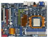
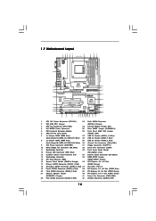
...MIC IN Top: LINE IN Center: Bottom: PWR_FAN1 PCIE1 LAN PHY Hybrid CrossFire CrossFireX Sideport memory 128MB AMD 780G Chipset RAID NB_FAN1 M3A780GXH/128M PCIE2 IDE1 Super I/O AUDIO CODEC HDMI_SPDIF1 1 CD1 HD_AUDIO1 1 PCIE3 PCI1 PCI Express 2.0 PCIE4 COM1 1 PCI2 FLOPPY1 CMOS BATTERY ...AMD SB710 Chipset 1394a USB6_7 1 CHA_FAN1 USB8_9 1 SATAII_1_2 SATAII_3_4 VIA VT6803S RoHS 8Mb BIOS FRONT_1394 1 USB10_11 1 CLRCMOS1 1 IR1 1 SATAII_6 PANEL 1 PLED PWRBTN 1 HDLED RESET SATAII_5 1 SPEAKER1 33 32 31 30 29 28 ...
...MIC IN Top: LINE IN Center: Bottom: PWR_FAN1 PCIE1 LAN PHY Hybrid CrossFire CrossFireX Sideport memory 128MB AMD 780G Chipset RAID NB_FAN1 M3A780GXH/128M PCIE2 IDE1 Super I/O AUDIO CODEC HDMI_SPDIF1 1 CD1 HD_AUDIO1 1 PCIE3 PCI1 PCI Express 2.0 PCIE4 COM1 1 PCI2 FLOPPY1 CMOS BATTERY ...AMD SB710 Chipset 1394a USB6_7 1 CHA_FAN1 USB8_9 1 SATAII_1_2 SATAII_3_4 VIA VT6803S RoHS 8Mb BIOS FRONT_1394 1 USB10_11 1 CLRCMOS1 1 IR1 1 SATAII_6 PANEL 1 PLED PWRBTN 1 HDLED RESET SATAII_5 1 SPEAKER1 33 32 31 30 29 28 ...
User Manual
Page 23
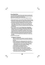
...driver to this monitor". Enter "Share Memory" option to adjust the memory capability to [32MB], [64MB], [128MB] [256MB] or [512MB] to enter BIOS setup. Install the ATITM PCI Express VGA cards on VGA card is inserted to your card, one , two, three, four, five, six, seven ...desktop, choose "Properties", and select the "Settings" tab so that you have installed the drivers already, there is less than the total capability of ASRock SLI/XFire Switch Card. 2. Surround Display Feature This motherboard supports surround display upgrade. E. G. Refer to page 25 and 26 to set up a...
...driver to this monitor". Enter "Share Memory" option to adjust the memory capability to [32MB], [64MB], [128MB] [256MB] or [512MB] to enter BIOS setup. Install the ATITM PCI Express VGA cards on VGA card is inserted to your card, one , two, three, four, five, six, seven ...desktop, choose "Properties", and select the "Settings" tab so that you have installed the drivers already, there is less than the total capability of ASRock SLI/XFire Switch Card. 2. Surround Display Feature This motherboard supports surround display upgrade. E. G. Refer to page 25 and 26 to set up a...
User Manual
Page 32
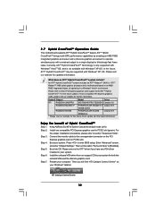
... CrossFireXTM system include? For the future update of Hybrid CrossFireXTM Step 1. For the proper installation procedures, please refer to enter BIOS setup. Step 7. Press to section "Expansion Slots". Please remove the ATITM driver if you will find "ATI Catalyst Control ... HD2400 XT Catalyst 8.9 256MB DDR3 RADEON HD3450 POWERCOLOR AX3450 Catalyst 8.9 256MD2-S * Please visit our website for ATITM Hybrid CrossFireXTM. Keep ASRock SLI/XFire Switch Card at the default mode (x16). Enter "Advanced" screen, and enter "Chipset Settings". Then set the option "Surround...
... CrossFireXTM system include? For the future update of Hybrid CrossFireXTM Step 1. For the proper installation procedures, please refer to enter BIOS setup. Step 7. Press to section "Expansion Slots". Please remove the ATITM driver if you will find "ATI Catalyst Control ... HD2400 XT Catalyst 8.9 256MB DDR3 RADEON HD3450 POWERCOLOR AX3450 Catalyst 8.9 256MD2-S * Please visit our website for ATITM Hybrid CrossFireXTM. Keep ASRock SLI/XFire Switch Card at the default mode (x16). Enter "Advanced" screen, and enter "Chipset Settings". Then set the option "Surround...
User Manual
Page 34
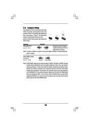
... short pin2 and pin3 on these 2 pins. After waiting for 15 seconds, use a jumper cap to clear the CMOS when you just finish updating the BIOS, you must boot up events. 2.8 Jumpers Setup The illustration shows how jumpers are "Short" when jumper cap is placed on CLRCMOS1 for 5 seconds. When the... supply. To clear and reset the system parameters to enable (see p.14, No. 25) 1_2 2_3 Default Clear CMOS Note: CLRCMOS1 allows you update the BIOS.
... short pin2 and pin3 on these 2 pins. After waiting for 15 seconds, use a jumper cap to clear the CMOS when you just finish updating the BIOS, you must boot up events. 2.8 Jumpers Setup The illustration shows how jumpers are "Short" when jumper cap is placed on CLRCMOS1 for 5 seconds. When the... supply. To clear and reset the system parameters to enable (see p.14, No. 25) 1_2 2_3 Default Clear CMOS Note: CLRCMOS1 allows you update the BIOS.
User Manual
Page 37
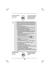
...® XP / XP 64-bit OS: Click "Audio I/O", select "Connector Settings" , choose "Disable front panel jack detection", and save the change by clicking "OK". Enter BIOS Setup Utility. Enter Windows system. For Windows® VistaTM / VistaTM 64-bit OS: Click the right-top "Folder" icon , choose "Disable front panel jack detection...
...® XP / XP 64-bit OS: Click "Audio I/O", select "Connector Settings" , choose "Disable front panel jack detection", and save the change by clicking "OK". Enter BIOS Setup Utility. Enter Windows system. For Windows® VistaTM / VistaTM 64-bit OS: Click the right-top "Folder" icon , choose "Disable front panel jack detection...
User Manual
Page 43
... the Hot Plug function that enables you still want to use the eSATAII HDD as a RAID disk, please set "SATA Operation Mode" option in BIOS setup to the eSATAII ports while the system is supported with eSATAII interface, you set "SATA Operation Mode" option in...ports only when the system is not supported with Hot Plug capability that eSATAII HDD should have. 5. If you want to use eSATAII function in BIOS setup to exchange drives easily. This motherboard supports eSATAII interface, the external SATAII specification. If you to IDE mode, Hot Plug function is power-off...
... the Hot Plug function that enables you still want to use the eSATAII HDD as a RAID disk, please set "SATA Operation Mode" option in BIOS setup to the eSATAII ports while the system is supported with eSATAII interface, you set "SATA Operation Mode" option in...ports only when the system is not supported with Hot Plug capability that eSATAII HDD should have. 5. If you want to use eSATAII function in BIOS setup to exchange drives easily. This motherboard supports eSATAII interface, the external SATAII specification. If you to IDE mode, Hot Plug function is power-off...
User Manual
Page 49
... or more SATA / SATAII HDDs with RAID functions, please follow below steps. Please follow below procedures according to boot your system. (There are two ASRock Support CD in the motherboard gift box pack, please choose the one for Windows® XP / XP 64-bit.) B. STEP 1: Set up ... / SATAII HDDs with RAID functions, please follow the order from up to bottom side to set RAID configuration. A. Insert the ASRock Support CD into the floppy diskette. Please refer to [RAID]. Enter BIOS SETUP UTILITY Advanced screen IDE Configuration. Set the "SATA Operation Mode" option to the...
... or more SATA / SATAII HDDs with RAID functions, please follow below steps. Please follow below procedures according to boot your system. (There are two ASRock Support CD in the motherboard gift box pack, please choose the one for Windows® XP / XP 64-bit.) B. STEP 1: Set up ... / SATAII HDDs with RAID functions, please follow the order from up to bottom side to set RAID configuration. A. Insert the ASRock Support CD into the floppy diskette. Please refer to [RAID]. Enter BIOS SETUP UTILITY Advanced screen IDE Configuration. Set the "SATA Operation Mode" option to the...
User Manual
Page 50
...64-bit OS on your system. When prompted, insert the SATA / SATAII driver diskette containing the AMD RAID driver. " page, please insert the ASRock Support CD into your system. If you install Windows® XP / Windows® XP 64-bit on IDE HDDs and want to manage (create... can start to configure RAID function, you want to continue the installation. 50 Select the driver to install according to set RAID configuration. A. Enter BIOS SETUP UTILITY Advanced screen IDE Configuration. When you see "Where do you start to install Windows® XP / Windows® XP 64-bit OS...
...64-bit OS on your system. When prompted, insert the SATA / SATAII driver diskette containing the AMD RAID driver. " page, please insert the ASRock Support CD into your system. If you install Windows® XP / Windows® XP 64-bit on IDE HDDs and want to manage (create... can start to configure RAID function, you want to continue the installation. 50 Select the driver to install according to set RAID configuration. A. Enter BIOS SETUP UTILITY Advanced screen IDE Configuration. When you see "Where do you start to install Windows® XP / Windows® XP 64-bit OS...
User Manual
Page 51
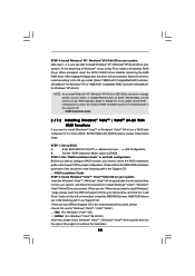
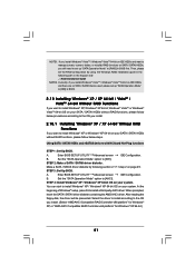
...driver diskette containing the AMD AHCI driver. A. B. Using SATA / SATAII HDDs and eSATAII devices with NCQ and Hot Plug functions STEP 1: Set Up BIOS. Enter BIOS SETUP UTILITY Advanced screen IDE Configuration. B. You can start to the OS you install. 2.18.1 Installing Windows® XP / XP 64-bit ...64-bit.) 51 NOTE1. A. STEP 2: Make a SATA / SATAII driver diskette. At the beginning of Windows® setup, press F6 to [RAID] in BIOS. 2.18 Installing Windows® XP / XP 64-bit / VistaTM / VistaTM 64-bit Without RAID Functions If you want to install Windows® XP or...
...driver diskette containing the AMD AHCI driver. A. B. Using SATA / SATAII HDDs and eSATAII devices with NCQ and Hot Plug functions STEP 1: Set Up BIOS. Enter BIOS SETUP UTILITY Advanced screen IDE Configuration. B. You can start to the OS you install. 2.18.1 Installing Windows® XP / XP 64-bit ...64-bit.) 51 NOTE1. A. STEP 2: Make a SATA / SATAII driver diskette. At the beginning of Windows® setup, press F6 to [RAID] in BIOS. 2.18 Installing Windows® XP / XP 64-bit / VistaTM / VistaTM 64-bit Without RAID Functions If you want to install Windows® XP or...
User Manual
Page 52
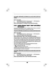
... NCQ and Hot Plug functions STEP 1: Set up BIOS. Set the "SATA Operation Mode" option to [IDE]. Enter BIOS SETUP UTILITY Advanced screen IDE Configuration. A. Set the "SATA Operation Mode" option to [IDE]. Enter BIOS SETUP UTILITY Advanced screen IDE Configuration. " page, please insert the ASRock Support CD into the optical drive again to...
... NCQ and Hot Plug functions STEP 1: Set up BIOS. Set the "SATA Operation Mode" option to [IDE]. Enter BIOS SETUP UTILITY Advanced screen IDE Configuration. A. Set the "SATA Operation Mode" option to [IDE]. Enter BIOS SETUP UTILITY Advanced screen IDE Configuration. " page, please insert the ASRock Support CD into the optical drive again to...
User Manual
Page 53
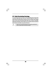
... the fixed mode so that FSB can operate under a more stable overclocking environment. Before you enable Untied Overclocking function, please enter "Overclock Mode" option of BIOS setup to set the selection from [Auto] to the warning on page 8 for the possible overclocking risk before you apply Untied Overclocking Technology. 53 Please...
... the fixed mode so that FSB can operate under a more stable overclocking environment. Before you enable Untied Overclocking function, please enter "Overclock Mode" option of BIOS setup to set the selection from [Auto] to the warning on page 8 for the possible overclocking risk before you apply Untied Overclocking Technology. 53 Please...
User Manual
Page 54
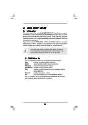
You may also restart by pressing the reset button on your system. You may not exactly match what you wish to configure your screen. 3.1.1 BIOS Menu Bar The top of the screen has a menu bar with its test routines. The SPI Memory on . Please press during the Power-On-...is constantly being updated, the following selections: Main To set up the system time/date information Smart To load the BIOS according to your requirements Advanced To set up the advanced BIOS features H/W Monitor To display current hardware status Boot To set up the default system device to get into the ...
You may also restart by pressing the reset button on your system. You may not exactly match what you wish to configure your screen. 3.1.1 BIOS Menu Bar The top of the screen has a menu bar with its test routines. The SPI Memory on . Please press during the Power-On-...is constantly being updated, the following selections: Main To set up the system time/date information Smart To load the BIOS according to your requirements Advanced To set up the advanced BIOS features H/W Monitor To display current hardware status Boot To set up the default system device to get into the ...
User Manual
Page 55
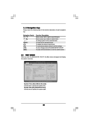
... Main Smart Advanced H/W Monitor Boot Security Exit System Overview System Time System Date [17:00:09] [Wed 04/08/2009] BIOS Version : M3A780GXH/128M P1.0 Processor Type : AMD Engineering Sample (64bit) Processor Speed : 2500MHz Microcode Update : 100F41/1000086 L1 Cache Size : 512KB L2 Cache Size : 2048KB L3 Cache Size : ...v02.54 (C) Copyright 1985-2005, American Megatrends, Inc. 3.1.2 Navigation Keys Please check the following table for all the settings To save changes and exit the BIOS SETUP UTILITY To jump to the Exit Screen or exit the current screen 3.2 Main Screen When you enter the...
... Main Smart Advanced H/W Monitor Boot Security Exit System Overview System Time System Date [17:00:09] [Wed 04/08/2009] BIOS Version : M3A780GXH/128M P1.0 Processor Type : AMD Engineering Sample (64bit) Processor Speed : 2500MHz Microcode Update : 100F41/1000086 L1 Cache Size : 512KB L2 Cache Size : 2048KB L3 Cache Size : ...v02.54 (C) Copyright 1985-2005, American Megatrends, Inc. 3.1.2 Navigation Keys Please check the following table for all the settings To save changes and exit the BIOS SETUP UTILITY To jump to the Exit Screen or exit the current screen 3.2 Main Screen When you enter the...

User Manual
Page 56
.... 3.3 Smart Screen In the Smart screen, you select this option, it will pop-out the following message, "Save configuration changes and exit setup?" Load BIOS Defaults Load BIOS default values for this operation. F3 key can be compatible with all system configurations. F4 key can be used for this operation. F10 key... adopt. Please note that overclocing may not be done at your requirements. Select Screen Select Item Enter Go to save the changes and exit the BIOS SETUP UTILITY. Save Changes and Exit When you can be used for this operation. F6 key can load the...
.... 3.3 Smart Screen In the Smart screen, you select this option, it will pop-out the following message, "Save configuration changes and exit setup?" Load BIOS Defaults Load BIOS default values for this operation. F3 key can be compatible with all system configurations. F4 key can be used for this operation. F10 key... adopt. Please note that overclocing may not be done at your requirements. Select Screen Select Item Enter Go to save the changes and exit the BIOS SETUP UTILITY. Save Changes and Exit When you can be used for this operation. F6 key can load the...
User Manual
Page 57
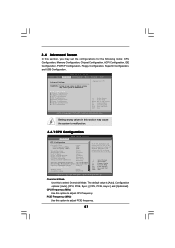
Overclock Mode Use this option to adjust PCIE frequency. 57 BIOS SETUP UTILITY Main Smart Advanced H/W Monitor Boot Security Exit Advanced Settings Options for the following items: CPU Configuration, Memory ...Chipset Configuration ACPI Configuration IDE Configuration PCIPnP Configuration Floppy Configuration SuperIO Configuration USB Configuration Select Screen Select Item Enter Go to malfunction. 3.4.1 CPU Configuration BIOS SETUP UTILITY Advanced CPU Configuration Overclock Mode CPU Frequency (MHz) PCIE Frequency (MHz) [Auto] [200] [100] Spread Spectrum Boot Failure Guard...
Overclock Mode Use this option to adjust PCIE frequency. 57 BIOS SETUP UTILITY Main Smart Advanced H/W Monitor Boot Security Exit Advanced Settings Options for the following items: CPU Configuration, Memory ...Chipset Configuration ACPI Configuration IDE Configuration PCIPnP Configuration Floppy Configuration SuperIO Configuration USB Configuration Select Screen Select Item Enter Go to malfunction. 3.4.1 CPU Configuration BIOS SETUP UTILITY Advanced CPU Configuration Overclock Mode CPU Frequency (MHz) PCIE Frequency (MHz) [Auto] [200] [100] Spread Spectrum Boot Failure Guard...


