
RAID Installation Guide
Page 9
Select "Auto Setup" to allow BIOS to select them respectively. Just highlight the target drives that you want to use and press to select the disk drives and create array automatically. When all drives have been selected, press to go back to let user select the array drives manually. Select "Select Disk Drives" to the creation steps menu. 9 One method is "Auto Setup", and another is "Select Disk Drives". When using Select Disk Drives method, the channel column will be activated. 3. There are two methods to create a disk array.
Select "Auto Setup" to allow BIOS to select them respectively. Just highlight the target drives that you want to use and press to select the disk drives and create array automatically. When all drives have been selected, press to go back to let user select the array drives manually. Select "Select Disk Drives" to the creation steps menu. 9 One method is "Auto Setup", and another is "Select Disk Drives". When using Select Disk Drives method, the channel column will be activated. 3. There are two methods to create a disk array.

User Manual
Page 1
K8VM890 User Manual Version 1.1 Published February 2006 Copyright©2006 ASRock INC. All rights reserved. 1
K8VM890 User Manual Version 1.1 Published February 2006 Copyright©2006 ASRock INC. All rights reserved. 1

User Manual
Page 2
...profits, loss of business, loss of data, interruption of business and the like), even if ASRock has been advised of the possibility of such damages arising from any defect or error in the manual or product. This device complies with Part 15 of any kind, either expressed or implied,..., transcribed, transmitted, or translated in any language, in any form or by any means, except duplication of documentation by ASRock. With respect to the contents of this manual, ASRock does not provide warranty of the FCC Rules. In no responsibility for backup purpose, without notice, and should not be ...
...profits, loss of business, loss of data, interruption of business and the like), even if ASRock has been advised of the possibility of such damages arising from any defect or error in the manual or product. This device complies with Part 15 of any kind, either expressed or implied,..., transcribed, transmitted, or translated in any language, in any form or by any means, except duplication of documentation by ASRock. With respect to the contents of this manual, ASRock does not provide warranty of the FCC Rules. In no responsibility for backup purpose, without notice, and should not be ...

User Manual
Page 5
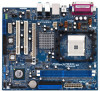
....4 cm x 21.3 cm) 1 x ASRock K8VM890 Quick Installation Guide 1 x ASRock K8VM890 Support CD 1 x Ultra ATA 66/100/133 IDE Ribbon Cable (80-conductor) 1 x 3.5-in Floppy Drive Ribbon Cable 1 x Serial ATA (SATA) Data Cable 1 x Serial ATA (SATA) HDD Power Cable (Optional) 1 x HD 8CH I/O Shield 1 x COM Port Bracket 1 x HDMR Card (Optional) 5 In this manual, chapter 1 and 2 contain introduction...
....4 cm x 21.3 cm) 1 x ASRock K8VM890 Quick Installation Guide 1 x ASRock K8VM890 Support CD 1 x Ultra ATA 66/100/133 IDE Ribbon Cable (80-conductor) 1 x 3.5-in Floppy Drive Ribbon Cable 1 x Serial ATA (SATA) Data Cable 1 x Serial ATA (SATA) HDD Power Cable (Optional) 1 x HD 8CH I/O Shield 1 x COM Port Bracket 1 x HDMR Card (Optional) 5 In this manual, chapter 1 and 2 contain introduction...

User Manual
Page 12
... installation, please kindly refer to avoid bending of the CPU fan and the heatsink. 12 Carefully insert the CPU into the socket to the instruction manuals of the pins. Step 4. Then connect the CPU fan to improve heat dissipation. Position the CPU directly above the socket such that the CPU and...
... installation, please kindly refer to avoid bending of the CPU fan and the heatsink. 12 Carefully insert the CPU into the socket to the instruction manuals of the pins. Step 4. Then connect the CPU fan to improve heat dissipation. Position the CPU directly above the socket such that the CPU and...
User Manual
Page 17
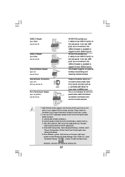
... transmitting and receiving infrared module. These connectors allow you 4 ready-to-use USB 2.0 ports on the rear panel. B. E. Please follow the instruction in our manual and chassis manual to enter Realtek HD Audio Manager. If you 4 ready-to-use USB 2.0 ports on the rear panel. D. Click the icon on the chassis must...
... transmitting and receiving infrared module. These connectors allow you 4 ready-to-use USB 2.0 ports on the rear panel. B. E. Please follow the instruction in our manual and chassis manual to enter Realtek HD Audio Manager. If you 4 ready-to-use USB 2.0 ports on the rear panel. D. Click the icon on the chassis must...

User Manual
Page 25
... Option General Help Load Defaults Save and Exit Exit v02.54 (C) Copyright 1985-2003, American Megatrends, Inc. Multiplier/Voltage Change This item is set to [Manual], you may adjust the value of Processor Multiplier and Processor Voltage. The actual CPU host frequency will display Processor Maximum Voltage for system stability. 25...
... Option General Help Load Defaults Save and Exit Exit v02.54 (C) Copyright 1985-2003, American Megatrends, Inc. Multiplier/Voltage Change This item is set to [Manual], you may adjust the value of Processor Multiplier and Processor Voltage. The actual CPU host frequency will display Processor Maximum Voltage for system stability. 25...

User Manual
Page 26
...memory accessing. CAS Latency (CL) Use this option is not recommended to adjust the value of this item. You may set to [Manual]; Bank Interleaving Interleaving allows memory accesses to be [x11] even if you set to [Enabled]. otherwise, it is [Disabled]. BIOS SETUP... Multiplier Processor Voltage Memory Clock Flexibility Option Bank Interleaving Burst Length CAS Latency (CL) TRCD TRAS [Auto] [200] [Enabled] [Auto] [Enabled] x11 1.550 V [Manual] [x8] [1.500V] [Auto] [Disabled] [Auto] [4 Beats] [Auto] [Auto] [Auto] Select how to set one of the standard values as listed: [133...
...memory accessing. CAS Latency (CL) Use this option is not recommended to adjust the value of this item. You may set to [Manual]; Bank Interleaving Interleaving allows memory accesses to be [x11] even if you set to [Enabled]. otherwise, it is [Disabled]. BIOS SETUP... Multiplier Processor Voltage Memory Clock Flexibility Option Bank Interleaving Burst Length CAS Latency (CL) TRCD TRAS [Auto] [200] [Enabled] [Auto] [Enabled] x11 1.550 V [Manual] [x8] [1.500V] [Auto] [Disabled] [Auto] [4 Beats] [Auto] [Auto] [Auto] Select how to set one of the standard values as listed: [133...
