RAID Installation Guide
Page 2
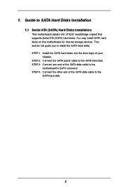
... devices. STEP 3: Connect one end of your chassis. STEP 1: Install the SATA hard disks into the drive bays of the SATA data cable to the motherboard's SATA connector. STEP 2: Connect the SATA power cable to the SATA hard disk. 2 1. STEP 4: Connect the other end of the SATA data cable to the... disk. Guide to install the SATA hard disks. This section will guide you to SATA Hard Disks Installation 1.1 Serial ATA (SATA) Hard Disks Installation This motherboard adopts VIA VT8237 southbridge chipset that supports Serial ATA (SATA) hard disks.
... devices. STEP 3: Connect one end of your chassis. STEP 1: Install the SATA hard disks into the drive bays of the SATA data cable to the motherboard's SATA connector. STEP 2: Connect the SATA power cable to the SATA hard disk. 2 1. STEP 4: Connect the other end of the SATA data cable to the... disk. Guide to install the SATA hard disks. This section will guide you to SATA Hard Disks Installation 1.1 Serial ATA (SATA) Hard Disks Installation This motherboard adopts VIA VT8237 southbridge chipset that supports Serial ATA (SATA) hard disks.
RAID Installation Guide
Page 4
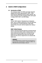
For optimal performance, please install identical drives of RAID This motherboard adopts VIA VT8237 south bridge chipset that optimizes two identical hard disk drives to configure RAID 0, RAID 1, and JBOD settings. It will improve data access ...
For optimal performance, please install identical drives of RAID This motherboard adopts VIA VT8237 south bridge chipset that optimizes two identical hard disk drives to configure RAID 0, RAID 1, and JBOD settings. It will improve data access ...

User Manual
Page 3
... Configuration 34 3.4 Hardware Health Event Monitoring Screen 35 3.5 Boot Screen 35 3.5.1 Boot Settings Configuration 36 3.6 Security Screen 36 3.7 Exit Screen 37 3 Introduction 5 1.1 Package Contents 5 1.2 Specifications 6 1.3 Motherboard Layout 8 1.4 HD 8CH I/O 10 2 . Contents 1 . Installation 11 Pre-installation Precautions 11 2.1 CPU Installation 12 2.2 Installation of CPU Fan and Heatsink 12 2.3 Installation of Memory Modules...
... Configuration 34 3.4 Hardware Health Event Monitoring Screen 35 3.5 Boot Screen 35 3.5.1 Boot Settings Configuration 36 3.6 Security Screen 36 3.7 Exit Screen 37 3 Introduction 5 1.1 Package Contents 5 1.2 Specifications 6 1.3 Motherboard Layout 8 1.4 HD 8CH I/O 10 2 . Contents 1 . Installation 11 Pre-installation Precautions 11 2.1 CPU Installation 12 2.2 Installation of CPU Fan and Heatsink 12 2.3 Installation of Memory Modules...

User Manual
Page 5
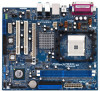
Introduction Thank you for purchasing ASRock K8VM890 motherboard, a reliable motherboard produced under ASRock's consistently stringent quality control. You may find the latest VGA cards and CPU support lists on ASRock website without notice. In this manual, chapter 1 and 2 contain ...this manual will be subject to quality and endurance. ASRock website http://www.asrock.com 1.1 Package Contents 1 x ASRock K8VM890 Motherboard (Micro ATX Form Factor: 9.6-in x 8.4-in, 24.4 cm x 21.3 cm) 1 x ASRock K8VM890 Quick Installation Guide 1 x ASRock K8VM890 Support CD 1 x Ultra ATA 66/100/133 IDE...
Introduction Thank you for purchasing ASRock K8VM890 motherboard, a reliable motherboard produced under ASRock's consistently stringent quality control. You may find the latest VGA cards and CPU support lists on ASRock website without notice. In this manual, chapter 1 and 2 contain ...this manual will be subject to quality and endurance. ASRock website http://www.asrock.com 1.1 Package Contents 1 x ASRock K8VM890 Motherboard (Micro ATX Form Factor: 9.6-in x 8.4-in, 24.4 cm x 21.3 cm) 1 x ASRock K8VM890 Quick Installation Guide 1 x ASRock K8VM890 Support CD 1 x Ultra ATA 66/100/133 IDE...

User Manual
Page 7
AMI Legal BIOS - Supports jumperfree - CPU Temperature Sensing - Motherboard Temperature Sensing - CPU/Chassis FAN connector - 20 pin ATX power connector - 4 pin 12V power connector - CPU Fan Tachometer - Microsoft® Windows® 2000 / XP / XP ...
AMI Legal BIOS - Supports jumperfree - CPU Temperature Sensing - Motherboard Temperature Sensing - CPU/Chassis FAN connector - 20 pin ATX power connector - 4 pin 12V power connector - CPU Fan Tachometer - Microsoft® Windows® 2000 / XP / XP ...

User Manual
Page 8
... Please check the table on page 21 for proper connection. 6. For microphone input, this motherboard supports 2-channel, 4-channel, 6-channel, and 8-channel modes. CAUTION! 1. Although this motherboard offers stepless control, it is strongly recommended to enable AMD's Cool 'n' QuietTM technology under ... for details. 2. See APPENDIX on the motherboard functions properly and unplug the power cord, then plug it back again. For audio output, this motherboard supports both stereo and mono modes. This motherboard supports Untied Overclocking Technology. Frequencies other than ...
... Please check the table on page 21 for proper connection. 6. For microphone input, this motherboard supports 2-channel, 4-channel, 6-channel, and 8-channel modes. CAUTION! 1. Although this motherboard offers stepless control, it is strongly recommended to enable AMD's Cool 'n' QuietTM technology under ... for details. 2. See APPENDIX on the motherboard functions properly and unplug the power cord, then plug it back again. For audio output, this motherboard supports both stereo and mono modes. This motherboard supports Untied Overclocking Technology. Frequencies other than ...

User Manual
Page 11
... the power cord is a Micro ATX form factor (9.6-in x 8.4-in, 24.4 cm x 21.3 cm) motherboard. Before you install motherboard components or change any component. 2. Also remember to the motherboard, peripherals, and/or components. 1. Doing so may cause severe damage to use a grounded wrist strap or touch... NEVER place your chassis to ensure that the motherboard fits into the screw holes to secure the motherboard to do not touch the ICs. 4. Hold components by the edges and do so may damage the motherboard. 11 Installation K8VM890 is detached from the wall socket before you ...
... the power cord is a Micro ATX form factor (9.6-in x 8.4-in, 24.4 cm x 21.3 cm) motherboard. Before you install motherboard components or change any component. 2. Also remember to the motherboard, peripherals, and/or components. 1. Doing so may cause severe damage to use a grounded wrist strap or touch... NEVER place your chassis to ensure that the motherboard fits into the screw holes to secure the motherboard to do not touch the ICs. 4. Hold components by the edges and do so may damage the motherboard. 11 Installation K8VM890 is detached from the wall socket before you ...

User Manual
Page 12
... the socket corner with each other. The CPU fits only in place. The lever clicks on the socket while you install the CPU into this motherboard, it firmly on the side tab to improve heat dissipation. Carefully insert the CPU into the socket to a 90o angle. DO NOT force the CPU...
... the socket corner with each other. The CPU fits only in place. The lever clicks on the socket while you install the CPU into this motherboard, it firmly on the side tab to improve heat dissipation. Carefully insert the CPU into the socket to a 90o angle. DO NOT force the CPU...

User Manual
Page 13
... 1. Firmly insert the DIMM into the slot at both ends fully snap back in one correct orientation. 2.3 Installation of Memory Modules (DIMM) This motherboard is properly seated. 13 Please make sure to the motherboard and the DIMM if you force the DIMM into the slot until the retaining clips at incorrect orientation.
... 1. Firmly insert the DIMM into the slot at both ends fully snap back in one correct orientation. 2.3 Installation of Memory Modules (DIMM) This motherboard is properly seated. 13 Please make sure to the motherboard and the DIMM if you force the DIMM into the slot until the retaining clips at incorrect orientation.

User Manual
Page 14
...x 1 slot) is [Auto], which will disable onboard VGA function when installing VGA card. HDMR slot: The HDMR slot is completely seated on K8VM890 motherboard. Installing an expansion card Step 1. Step 5. Fasten the card to the chassis with v.92 Modem functionality. The default value of the system memory...: PCI slots are 2 PCI Express slots, 2 PCI slots and 1 HDMR slot on the slot. Step 2. Remove the system unit cover (if your motherboard is unplugged. Step 3. Keep the screws for PCI Express cards, such as Gigabit LAN card, SATA2 card, etc. Step 4. Replace the system cover. ...
...x 1 slot) is [Auto], which will disable onboard VGA function when installing VGA card. HDMR slot: The HDMR slot is completely seated on K8VM890 motherboard. Installing an expansion card Step 1. Step 5. Fasten the card to the chassis with v.92 Modem functionality. The default value of the system memory...: PCI slots are 2 PCI Express slots, 2 PCI slots and 1 HDMR slot on the slot. Step 2. Remove the system unit cover (if your motherboard is unplugged. Step 3. Keep the screws for PCI Express cards, such as Gigabit LAN card, SATA2 card, etc. Step 4. Replace the system cover. ...

User Manual
Page 16
...and connectors are NOT jumpers. Placing jumper caps over these headers and connectors. Serial ATA (SATA) Data Cable Either end of the motherboard! The current SATA SATA1 interface allows up to optimize compatibility and performance, please connect your IDE device vendor for internal storage devices.... caps over the headers and connectors will cause permanent damage of the SATA data cable can be connected to the power connector on this motherboard, please set the IDE device as "Master". FDD Connector (33-pin FLOPPY1) (see p.9, No. 23) Pin1 FLOPPY1 the red-striped...
...and connectors are NOT jumpers. Placing jumper caps over these headers and connectors. Serial ATA (SATA) Data Cable Either end of the motherboard! The current SATA SATA1 interface allows up to optimize compatibility and performance, please connect your IDE device vendor for internal storage devices.... caps over the headers and connectors will cause permanent damage of the SATA data cable can be connected to the power connector on this motherboard, please set the IDE device as "Master". FDD Connector (33-pin FLOPPY1) (see p.9, No. 23) Pin1 FLOPPY1 the red-striped...

User Manual
Page 19
... SATA HDD. STEP 3: Connect one end of the SATA data cable to the SATA hard disk. 2.9 Hot Plug and Hot Swap Functions for SATA HDDs K8VM890 motherboard supports Hot Plug and Hot Swap functions for SATA Devices. What is Hot Plug Function? COM Port Header (9-pin COM1) (see p.9 No. 30) RRXD1 DDTR... and remove the SATA HDDs while the system is still power-on and in working condition. 19 STEP 2: Connect the SATA power cable to the motherboard's SATA connector. If SATA HDDs are NOT set for RAID configuration, it is called "Hot Plug" for the action to insert and remove the SATA...
... SATA HDD. STEP 3: Connect one end of the SATA data cable to the SATA hard disk. 2.9 Hot Plug and Hot Swap Functions for SATA HDDs K8VM890 motherboard supports Hot Plug and Hot Swap functions for SATA Devices. What is Hot Plug Function? COM Port Header (9-pin COM1) (see p.9 No. 30) RRXD1 DDTR... and remove the SATA HDDs while the system is still power-on and in working condition. 19 STEP 2: Connect the SATA power cable to the motherboard's SATA connector. If SATA HDDs are NOT set for RAID configuration, it is called "Hot Plug" for the action to insert and remove the SATA...
User Manual
Page 21
... 2000 / XP / XP 64-bit OS on your system. Therefore, CPU FSB is no need to make a SATA driver diskette. 2.12 Untied Overclocking Technology This motherboard supports Untied Overclocing Technology, which means during overclocking, but PCI and PCIE buses are in Windows environment, please install SATA drivers from the Support CD...
... 2000 / XP / XP 64-bit OS on your system. Therefore, CPU FSB is no need to make a SATA driver diskette. 2.12 Untied Overclocking Technology This motherboard supports Untied Overclocing Technology, which means during overclocking, but PCI and PCIE buses are in Windows environment, please install SATA drivers from the Support CD...

User Manual
Page 22
... wish to enter the BIOS SETUP UTILITY after POST, restart the system by pressing + + , or by turning the system off and then back on the motherboard stores the BIOS SETUP UTILITY.
... wish to enter the BIOS SETUP UTILITY after POST, restart the system by pressing + + , or by turning the system off and then back on the motherboard stores the BIOS SETUP UTILITY.

User Manual
Page 25
... or disable the feature of this item to [Auto] by default. Spread Spectrum This item should always be [Disabled] for reference. Cool 'n' Quiet Use this motherboard. Processor Maximum Voltage It will display Processor Maximum Voltage for better system stability.
... or disable the feature of this item to [Auto] by default. Spread Spectrum This item should always be [Disabled] for reference. Cool 'n' Quiet Use this motherboard. Processor Maximum Voltage It will display Processor Maximum Voltage for better system stability.

User Manual
Page 35
... boot settings and the boot priority. 3.4 Hardware Health Event Monitoring Screen In this section, it allows you to monitor the status of the CPU temperature, motherboard temperature, CPU fan speed, chassis fan speed, and the critical voltage. Select Screen Select Item Enter Go to Sub Screen F1 General Help F9 Load...
... boot settings and the boot priority. 3.4 Hardware Health Event Monitoring Screen In this section, it allows you to monitor the status of the CPU temperature, motherboard temperature, CPU fan speed, chassis fan speed, and the critical voltage. Select Screen Select Item Enter Go to Sub Screen F1 General Help F9 Load...

User Manual
Page 38
.../ XP 64-bit. or you need to contact ASRock or want to know more information. 4.2 Support CD Information The Support CD that came with the motherboard contains necessary drivers and useful utilities that the motherboard supports. Because motherboard settings and hardware options vary, use the setup procedures... Menu if "AUTORUN" is enabled in your OS documentation for more about ASRock, welcome to activate the devices. 4.2.3 Utilities Menu The Utilities Menu shows the applications software that enhance the motherboard features. 4.2.1 Running The Support CD To begin using the support CD, ...
.../ XP 64-bit. or you need to contact ASRock or want to know more information. 4.2 Support CD Information The Support CD that came with the motherboard contains necessary drivers and useful utilities that the motherboard supports. Because motherboard settings and hardware options vary, use the setup procedures... Menu if "AUTORUN" is enabled in your OS documentation for more about ASRock, welcome to activate the devices. 4.2.3 Utilities Menu The Utilities Menu shows the applications software that enhance the motherboard features. 4.2.1 Running The Support CD To begin using the support CD, ...

