User Manual
Page 3
Installation 10 Pre-installation Precautions 10 2.1 CPU Installation 11 2.2 Installation of CPU Fan and Heatsink 11 2.3 Installation of Memory Modules (DIMM 12 2.4 Expansion Slots (Future CPU Port, PCI, AGP, and AMR Slots) ....... 13 2.5 Jumpers Setup 15 2.6 Onboard Headers and Connectors 16 2.7 Serial ATA (SATA)... Configuration 33 3.3.8 USB Configuration 34 3.4 Hardware Health Event Monitoring Screen 35 3.5 Boot Screen 35 3.5.1 Boot Settings Configuration 36 3 Introduction 5 1.1 Package Contents 5 1.2 Specifications 6 1.3 Motherboard Layout 8 1.4 ASRock I/O PlusTM 9 2 .
Installation 10 Pre-installation Precautions 10 2.1 CPU Installation 11 2.2 Installation of CPU Fan and Heatsink 11 2.3 Installation of Memory Modules (DIMM 12 2.4 Expansion Slots (Future CPU Port, PCI, AGP, and AMR Slots) ....... 13 2.5 Jumpers Setup 15 2.6 Onboard Headers and Connectors 16 2.7 Serial ATA (SATA)... Configuration 33 3.3.8 USB Configuration 34 3.4 Hardware Health Event Monitoring Screen 35 3.5 Boot Screen 35 3.5.1 Boot Settings Configuration 36 3 Introduction 5 1.1 Package Contents 5 1.2 Specifications 6 1.3 Motherboard Layout 8 1.4 ASRock I/O PlusTM 9 2 .

User Manual
Page 5
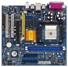
... Cable (Optional) 1 x Serial ATA (SATA) HDD Power Cable (Optional) 1 x ASRock I/O PlusTM Shield 1 x COM Port Bracket 1 x ASRock MR Card (Optional) 5 1. Introduction Thank you for purchasing ASRock K8Upgrade-VM800 motherboard, a reliable motherboard produced under ASRock's consistently stringent quality control. You may find the latest memory and CPU support lists on ASRock website without notice. Because the motherboard specifications and the...
... Cable (Optional) 1 x Serial ATA (SATA) HDD Power Cable (Optional) 1 x ASRock I/O PlusTM Shield 1 x COM Port Bracket 1 x ASRock MR Card (Optional) 5 1. Introduction Thank you for purchasing ASRock K8Upgrade-VM800 motherboard, a reliable motherboard produced under ASRock's consistently stringent quality control. You may find the latest memory and CPU support lists on ASRock website without notice. Because the motherboard specifications and the...
User Manual
Page 6
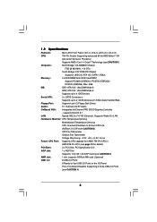
... CAUTION 1) Chipsets: North Bridge: VIA K8M800 Chipset FSB @ 800 MHz / 1.6 GT/s South Bridge: VIA VT8237R Chipset Supports USB 2.0, ATA 133, SATA 1.5Gb/s Memory: 2 x DDR DIMM Slots: DDR1 and DDR2 Support PC3200 (DDR400) / PC2700 (DDR333) / PC2100 (DDR266), Max. 2GB IDE: IDE1: ATA 133 / Ultra...(10/100 Ethernet), Supports Wake-On-LAN Hardware Monitor: CPU Temperature Sensing Motherboard Temperature Sensing CPU Overheat Shutdown to Protect CPU Life (ASRock U-COP)(see CAUTION 2) CPU Fan Tachometer Chassis Fan Tachometer Voltage Monitoring: +12V, +5V, +3.3V, Vcore Future CPU Port: ...
... CAUTION 1) Chipsets: North Bridge: VIA K8M800 Chipset FSB @ 800 MHz / 1.6 GT/s South Bridge: VIA VT8237R Chipset Supports USB 2.0, ATA 133, SATA 1.5Gb/s Memory: 2 x DDR DIMM Slots: DDR1 and DDR2 Support PC3200 (DDR400) / PC2700 (DDR333) / PC2100 (DDR266), Max. 2GB IDE: IDE1: ATA 133 / Ultra...(10/100 Ethernet), Supports Wake-On-LAN Hardware Monitor: CPU Temperature Sensing Motherboard Temperature Sensing CPU Overheat Shutdown to Protect CPU Life (ASRock U-COP)(see CAUTION 2) CPU Fan Tachometer Chassis Fan Tachometer Voltage Monitoring: +12V, +5V, +3.3V, Vcore Future CPU Port: ...

User Manual
Page 8
...1 1 J7 J8 1 1 J5 J6 1 1 J3 J4 1 1 J1 J2 VIA K8M800 Chipset FUTURE_CPU_PORT1 1 J9 1 J10 AGP 8X 1.5V_AGP1 PCI 1 K8Upgrade-VM800 AUDIO CODEC AMR1 PCI 2 1 COM1 DDR400 FLOPPY1 IDE1 IDE2 VIA VT8237R Chipset SATA1 SATA2 CMOS Battery CLRCMOS2 1 CHA_FAN1 SPEAKER1 1 USB67 1 PLED PWRBTN PANEL 1 ...North Bridge Controller 7 184-pin DDR DIMM Slots (DDR1- 2) 8 J9 / J10 / J15 Jumpers 9 Infrared Module Header (IR1) 10 Flash Memory 11 ATX Power Connector (ATXPWR1) 12 Floppy Connector (FLOPPY1) 13 Primary IDE Connector (IDE1, Blue) 14 Secondary IDE Connector (IDE2, Black) ...
...1 1 J7 J8 1 1 J5 J6 1 1 J3 J4 1 1 J1 J2 VIA K8M800 Chipset FUTURE_CPU_PORT1 1 J9 1 J10 AGP 8X 1.5V_AGP1 PCI 1 K8Upgrade-VM800 AUDIO CODEC AMR1 PCI 2 1 COM1 DDR400 FLOPPY1 IDE1 IDE2 VIA VT8237R Chipset SATA1 SATA2 CMOS Battery CLRCMOS2 1 CHA_FAN1 SPEAKER1 1 USB67 1 PLED PWRBTN PANEL 1 ...North Bridge Controller 7 184-pin DDR DIMM Slots (DDR1- 2) 8 J9 / J10 / J15 Jumpers 9 Infrared Module Header (IR1) 10 Flash Memory 11 ATX Power Connector (ATXPWR1) 12 Floppy Connector (FLOPPY1) 13 Primary IDE Connector (IDE1, Blue) 14 Secondary IDE Connector (IDE2, Black) ...
User Manual
Page 12
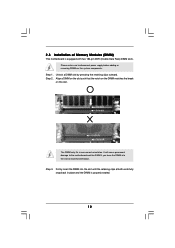
... (Double Data Rate) DIMM slots. Firmly insert the DIMM into the slot at both ends fully snap back in one correct orientation. Step 2. 2.3 Installation of Memory Modules (DIMM) This motherboard is properly seated. 12 Step 3. Step 1. Unlock a DIMM slot by pressing the retaining clips outward.
... (Double Data Rate) DIMM slots. Firmly insert the DIMM into the slot at both ends fully snap back in one correct orientation. Step 2. 2.3 Installation of Memory Modules (DIMM) This motherboard is properly seated. 12 Step 3. Step 1. Unlock a DIMM slot by pressing the retaining clips outward.
User Manual
Page 22
... hardware status Boot To set up the default system device to locate and load the Operating System Security To set up the computer. The Flash Memory on your system.
... hardware status Boot To set up the default system device to locate and load the Operating System Security To set up the computer. The Flash Memory on your system.
User Manual
Page 23
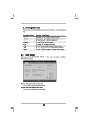
... Overview System Time System Date [10:00:09] [Mon 11/08/2004] BIOS Version Processor Type Processor Speed L1 Cache Size L2 Cache Size Total Memory DIMM 1 DIMM 2 : K8Upgrade-VM800 BIOS P1.00 : AMD Athlon(tm) 64 Processor 3400+ : 2200 MHz : 128KB : 1024KB : 512MB with 64MB shared... memory : 256MB/166MHz (DDR333) : None Use [Enter], [TAB] or [SHIFT-TAB] to configure system Time. +Tab F1 F9 F10 ESC Select Screen Select Item Change Field ...
... Overview System Time System Date [10:00:09] [Mon 11/08/2004] BIOS Version Processor Type Processor Speed L1 Cache Size L2 Cache Size Total Memory DIMM 1 DIMM 2 : K8Upgrade-VM800 BIOS P1.00 : AMD Athlon(tm) 64 Processor 3400+ : 2200 MHz : 128KB : 1024KB : 512MB with 64MB shared... memory : 256MB/166MHz (DDR333) : None Use [Enter], [TAB] or [SHIFT-TAB] to configure system Time. +Tab F1 F9 F10 ESC Select Screen Select Item Change Field ...

User Manual
Page 24
If ASRock 939CPU Board is installed into the FUTURE_CPU_PORT on this section may cause the system to malfunction. 24 CPU Configuration Chipset Configuration ACPI Configuration IDE Configuration ... 1 (K8_939) DDR 2 (K8_939) DDR 3 (K8_939) DDR 4 (K8_939) [17:00:09] [Mon 11/08/2004] : K8Upgrade-VM800 BIOS P1.0 : AMD Athlon(tm) 64 Processor 3400+ : 2200 MHz : 128KB : 1024KB : 512MB with 64MB shared memory Single Channel Memory Mode : 512MB/133MHz (DDR266) : None : None : None Use [Enter], [TAB] or [SHIFT-TAB] to Sub Screen F1 General...
If ASRock 939CPU Board is installed into the FUTURE_CPU_PORT on this section may cause the system to malfunction. 24 CPU Configuration Chipset Configuration ACPI Configuration IDE Configuration ... 1 (K8_939) DDR 2 (K8_939) DDR 3 (K8_939) DDR 4 (K8_939) [17:00:09] [Mon 11/08/2004] : K8Upgrade-VM800 BIOS P1.0 : AMD Athlon(tm) 64 Processor 3400+ : 2200 MHz : 128KB : 1024KB : 512MB with 64MB shared memory Single Channel Memory Mode : 512MB/133MHz (DDR266) : None : None : None Use [Enter], [TAB] or [SHIFT-TAB] to Sub Screen F1 General...
User Manual
Page 25
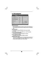
... BIOS SETUP UTILITY Advanced CPU Configuration CPU Host Frequency Actual Frequency (MHz) Spread Spectrum Cool' n' Quiet Processor Maximum Multiplier Processor Maximum Voltage Multiplier/Voltage Change Memory Clock Flexibility Option Bank Interleaving Burst Length CAS Latency (CL) TRCD TRAS TRP MA Timing [Auto] [200] [Auto] [Disabled] x11 1.550 V [Auto] [Auto] [Disabled] [Auto...
... BIOS SETUP UTILITY Advanced CPU Configuration CPU Host Frequency Actual Frequency (MHz) Spread Spectrum Cool' n' Quiet Processor Maximum Multiplier Processor Maximum Voltage Multiplier/Voltage Change Memory Clock Flexibility Option Bank Interleaving Burst Length CAS Latency (CL) TRCD TRAS TRP MA Timing [Auto] [200] [Auto] [Disabled] x11 1.550 V [Auto] [Auto] [Disabled] [Auto...

User Manual
Page 26
... Frequency Actual Frequency (MHz) Spread Spectrum Cool' n' Quiet Processor Maximum Multiplier Processor Maximum Voltage Multiplier/Voltage Change Processor Multiplier Processor Voltage Memory Clock Flexibility Option Bank Interleaving Burst Length CAS Latency (CL) TRCD MA Timing [Auto] [200] [Auto] [Disabled] x11 1....Voltage This item will show when "Multiplier/Voltage Change" is not recommended to adjust the value of this item to [0.800V]. Memory Clock This item can be hidden. Configuration options: [Auto], [2.0], [3.0], and [2.5]. 26 otherwise, it is set the value ...
... Frequency Actual Frequency (MHz) Spread Spectrum Cool' n' Quiet Processor Maximum Multiplier Processor Maximum Voltage Multiplier/Voltage Change Processor Multiplier Processor Voltage Memory Clock Flexibility Option Bank Interleaving Burst Length CAS Latency (CL) TRCD MA Timing [Auto] [200] [Auto] [Disabled] x11 1....Voltage This item will show when "Multiplier/Voltage Change" is not recommended to adjust the value of this item to [0.800V]. Memory Clock This item can be hidden. Configuration options: [Auto], [2.0], [3.0], and [2.5]. 26 otherwise, it is set the value ...
User Manual
Page 27
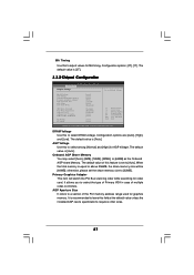
MA Timing Use this to select among [Normal] and [High] for AGP Voltage. DRAM Voltage AGP Voltage Onboard AGP Share Memory Primary Graphics Adapter AGP Aperture Size AGP Mode AGP Fast Write IDE Drive Strength PCI Delay Transaction OnBoard LAN OnBoard AC'97 Audio OnBoard... 1985-2003, American Megatrends, Inc. AGP Voltage Use this to adjust values for MA timing. When the total memory is [Auto]. The default value of the PCI memory address range used for video card. Onboard AGP Share Memory You may select [Auto], [8MB], [16MB], [32MB], or [64MB] as the Onboard AGP share...
MA Timing Use this to select among [Normal] and [High] for AGP Voltage. DRAM Voltage AGP Voltage Onboard AGP Share Memory Primary Graphics Adapter AGP Aperture Size AGP Mode AGP Fast Write IDE Drive Strength PCI Delay Transaction OnBoard LAN OnBoard AC'97 Audio OnBoard... 1985-2003, American Megatrends, Inc. AGP Voltage Use this to adjust values for MA timing. When the total memory is [Auto]. The default value of the PCI memory address range used for video card. Onboard AGP Share Memory You may select [Auto], [8MB], [16MB], [32MB], or [64MB] as the Onboard AGP share...

Quick Installation Guide
Page 2
J8 Jumpers 2 ASRock K8Upgrade-VM800 Motherboard Motherboard Layout English 1 PS2_USB_PWR1 Jumper 2 ATX 12V Power Connector (ATX12V1) 3 CPU Fan Connector (CPU_FAN1) 4 754-Pin CPU Socket 5 CPU Heatsink Retention Module 6 North Bridge Controller 7 184-pin DDR DIMM Slots (DDR1- 2) 8 J9 / J10 / J15 Jumpers 9 Infrared Module Header (IR1) 10 Flash Memory 11 ATX Power Connector (ATXPWR1) 12 Floppy...
J8 Jumpers 2 ASRock K8Upgrade-VM800 Motherboard Motherboard Layout English 1 PS2_USB_PWR1 Jumper 2 ATX 12V Power Connector (ATX12V1) 3 CPU Fan Connector (CPU_FAN1) 4 754-Pin CPU Socket 5 CPU Heatsink Retention Module 6 North Bridge Controller 7 184-pin DDR DIMM Slots (DDR1- 2) 8 J9 / J10 / J15 Jumpers 9 Infrared Module Header (IR1) 10 Flash Memory 11 ATX Power Connector (ATXPWR1) 12 Floppy...

Quick Installation Guide
Page 4
... be available on ASRock website as well. ASRock website http://www.asrock.com 1.1 Package Contents 1 x ASRock K8Upgrade-VM800 Motherboard (Micro ATX Form Factor: 9.0-in x 9.6-in, 22.9 cm x 24.4 cm) 1 x ASRock K8Upgrade-VM800 Quick Installation Guide 1 x ASRock K8Upgrade-VM800 Support CD 1 x Ultra ATA 66/100/133 IDE Ribbon Cable (80-conductor) 1 x 3.5-in the Support CD. You may find the latest memory and CPU support...
... be available on ASRock website as well. ASRock website http://www.asrock.com 1.1 Package Contents 1 x ASRock K8Upgrade-VM800 Motherboard (Micro ATX Form Factor: 9.0-in x 9.6-in, 22.9 cm x 24.4 cm) 1 x ASRock K8Upgrade-VM800 Quick Installation Guide 1 x ASRock K8Upgrade-VM800 Support CD 1 x Ultra ATA 66/100/133 IDE Ribbon Cable (80-conductor) 1 x 3.5-in the Support CD. You may find the latest memory and CPU support...

Quick Installation Guide
Page 5
...Chipsets: North Bridge: VIA K8M800 Chipset FSB @ 800 MHz / 1.6 GT/s South Bridge: VIA VT8237R Chipset Supports USB 2.0, ATA 133, SATA 1.5Gb/s Memory: 2 x DDR DIMM Slots: DDR1 and DDR2 Support PC3200 (DDR400) / PC2700 (DDR333) / PC2100 (DDR266), Max. 2GB IDE: IDE1: ATA 133...: 1 x AGP Slot Supports 1.5V, 8X / 4X AGP Card (see CAUTION 3) AMR slot: 1 slot, supports ASRock MR card (Optional) USB 2.0: 8 USB 2.0 Ports: 6 Ready-to-Use USB 2.0 Ports on the I/O Panel Plus 2 On-Board Headers Supporting 2 Extra USB 2.0 Ports (see CAUTION 4) English 5 ASRock K8Upgrade-VM800 Motherboard
...Chipsets: North Bridge: VIA K8M800 Chipset FSB @ 800 MHz / 1.6 GT/s South Bridge: VIA VT8237R Chipset Supports USB 2.0, ATA 133, SATA 1.5Gb/s Memory: 2 x DDR DIMM Slots: DDR1 and DDR2 Support PC3200 (DDR400) / PC2700 (DDR333) / PC2100 (DDR266), Max. 2GB IDE: IDE1: ATA 133...: 1 x AGP Slot Supports 1.5V, 8X / 4X AGP Card (see CAUTION 3) AMR slot: 1 slot, supports ASRock MR card (Optional) USB 2.0: 8 USB 2.0 Ports: 6 Ready-to-Use USB 2.0 Ports on the I/O Panel Plus 2 On-Board Headers Supporting 2 Extra USB 2.0 Ports (see CAUTION 4) English 5 ASRock K8Upgrade-VM800 Motherboard

Quick Installation Guide
Page 8
2.2 Installation of Memory Modules (DIMM) K8Upgrade-VM800 motherboard provides two 184-pin DDR (Double Data Rate) DIMM slots.... slots, 1 AGP slot and 1 AMR slot on K8UpgradeVM800 motherboard. Unlock a DIMM slot by installing an add-on ASRock 939CPU Board into the slot at both ends fully snap back in one correct orientation. Future CPU Port (Yellow-Colored Port...you to upgrade your AMD 754-Pin CPU to adjust the jumper settings for the correct jumper settings. 8 ASRock K8Upgrade-VM800 Motherboard English Step 1. Align a DIMM on the slot such that the notch on the DIMM matches the ...
2.2 Installation of Memory Modules (DIMM) K8Upgrade-VM800 motherboard provides two 184-pin DDR (Double Data Rate) DIMM slots.... slots, 1 AGP slot and 1 AMR slot on K8UpgradeVM800 motherboard. Unlock a DIMM slot by installing an add-on ASRock 939CPU Board into the slot at both ends fully snap back in one correct orientation. Future CPU Port (Yellow-Colored Port...you to upgrade your AMD 754-Pin CPU to adjust the jumper settings for the correct jumper settings. 8 ASRock K8Upgrade-VM800 Motherboard English Step 1. Align a DIMM on the slot such that the notch on the DIMM matches the ...
Quick Installation Guide
Page 19
It is a menu-driven program, which allows you to display the menus. 19 ASRock K8Upgrade-VM800 Motherboard English For the detailed information about BIOS Setup, please refer to the User Manual (PDF file) contained in the Support CD to scroll through ... to enter BIOS Setup after POST, please restart the system by pressing + + , or pressing the reset button on the file "ASSETUP. BIOS Information The Flash Memory on the motherboard stores BIOS Setup Utility. The BIOS Setup program is enabled in your CD-ROM drive. The Support CD that will display the...
It is a menu-driven program, which allows you to display the menus. 19 ASRock K8Upgrade-VM800 Motherboard English For the detailed information about BIOS Setup, please refer to the User Manual (PDF file) contained in the Support CD to scroll through ... to enter BIOS Setup after POST, please restart the system by pressing + + , or pressing the reset button on the file "ASSETUP. BIOS Information The Flash Memory on the motherboard stores BIOS Setup Utility. The BIOS Setup program is enabled in your CD-ROM drive. The Support CD that will display the...

