
RAID Installation Guide
Page 2
Guide to Serial ATA (SATA) Hard Disks Installation of "User Manual" in the support CD. You may install SATA hard disks on SATA ports. 2 This section will guide you how to create RAID on this motherboard for internal storage devices. For SATA installation guide, please refer to SATA Hard Disks Installation 1.1 Serial ATA (SATA) Hard Disks Installation ULi M1697 chipset supports Serial ATA (SATA) hard disks with RAID functions, including RAID 0, RAID 1, RAID 0+1, JBOD, and RAID 5. 1.
Guide to Serial ATA (SATA) Hard Disks Installation of "User Manual" in the support CD. You may install SATA hard disks on SATA ports. 2 This section will guide you how to create RAID on this motherboard for internal storage devices. For SATA installation guide, please refer to SATA Hard Disks Installation 1.1 Serial ATA (SATA) Hard Disks Installation ULi M1697 chipset supports Serial ATA (SATA) hard disks with RAID functions, including RAID 0, RAID 1, RAID 0+1, JBOD, and RAID 5. 1.
User Manual
Page 3
... Disk Setup Guide 29 2.11 Serial ATA (SATA) / Serial ATAII (SATAII) Hard Disks Installation 30 2.12 Hot Plug and Hot Swap Functions for SLITM Mode 9 1.4 Motherboard Layout 10 1.5 ASRock eSATAII I/O 11 2 .
... Disk Setup Guide 29 2.11 Serial ATA (SATA) / Serial ATAII (SATAII) Hard Disks Installation 30 2.12 Hot Plug and Hot Swap Functions for SLITM Mode 9 1.4 Motherboard Layout 10 1.5 ASRock eSATAII I/O 11 2 .

User Manual
Page 5
... endurance. In this manual occur, the updated version will be available on ASRock website as well. It delivers excellent performance with robust design conforming to ASRock's commitment to change without further notice. Introduction Thank you for purchasing ASRock K8SLI-eSATA2 motherboard, a reliable motherboard produced under ASRock's consistently stringent quality control. 1. You may find the latest VGA cards and...
... endurance. In this manual occur, the updated version will be available on ASRock website as well. It delivers excellent performance with robust design conforming to ASRock's commitment to change without further notice. Introduction Thank you for purchasing ASRock K8SLI-eSATA2 motherboard, a reliable motherboard produced under ASRock's consistently stringent quality control. 1. You may find the latest VGA cards and...

User Manual
Page 7
SLI/XFIRE power connector - Supports "Plug and Play" - Supports jumperfree - Drivers, Utilities, AntiVirus Software (Trial Version) - Motherboard Temperature Sensing - Front panel audio connector - 2 x USB 2.0 headers (support 4 USB 2.0 ports) (see CAUTION 7) - 2 x ATA133 IDE connectors (support 4 x IDE devices) - 1 x Floppy connector - 1 x IR header - 1 x Game header - ...
SLI/XFIRE power connector - Supports "Plug and Play" - Supports jumperfree - Drivers, Utilities, AntiVirus Software (Trial Version) - Motherboard Temperature Sensing - Front panel audio connector - 2 x USB 2.0 headers (support 4 USB 2.0 ports) (see CAUTION 7) - 2 x ATA133 IDE connectors (support 4 x IDE devices) - 1 x Floppy connector - 1 x IR header - 1 x Game header - ...

User Manual
Page 8
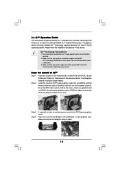
...overheat is strongly recommended to PCIE1 slot. Before you plan to install only one PCI Express VGA card to this motherboard, please install it is not supported with eSATAII interface on page 26 for SLITM function. Please read "Untied ... 2. Power Management for SLITM Mode" on page 17 for details. 3. Although this motherboard.) 8. This motherboard supports eSATAII interface, the external SATAII specification. Please read "eSATAII Interface Introduction" on this motherboard offers stepless control, it to enable AMD's Cool 'n' QuietTM technology under Microsoft®...
...overheat is strongly recommended to PCIE1 slot. Before you plan to install only one PCI Express VGA card to this motherboard, please install it is not supported with eSATAII interface on page 26 for SLITM function. Please read "Untied ... 2. Power Management for SLITM Mode" on page 17 for details. 3. Although this motherboard.) 8. This motherboard supports eSATAII interface, the external SATAII specification. Please read "eSATAII Interface Introduction" on this motherboard offers stepless control, it to enable AMD's Cool 'n' QuietTM technology under Microsoft®...

User Manual
Page 12
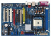
...to static electricity, NEVER place your chassis to ensure that the motherboard fits into the screw holes to secure the motherboard to the motherboard, peripherals, and/or components. 1. Whenever you install or remove any component. 2. Installation K8SLI-eSATA2 is an ATX form factor (12.0-in x 8.2-in the ...bag that the power is switched off or the power cord is detached from the wall socket before you install motherboard components or change any component, place it ...
...to static electricity, NEVER place your chassis to ensure that the motherboard fits into the screw holes to secure the motherboard to the motherboard, peripherals, and/or components. 1. Whenever you install or remove any component. 2. Installation K8SLI-eSATA2 is an ATX form factor (12.0-in x 8.2-in the ...bag that the power is switched off or the power cord is detached from the wall socket before you install motherboard components or change any component, place it ...
User Manual
Page 13
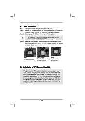
... of the pins. Then connect the CPU fan to improve heat dissipation. The lever clicks on the socket while you install the CPU into this motherboard, it fits in one correct orientation. When the CPU is necessary to install a larger heatsink and cooling fan to avoid bending of the CPU fan...
... of the pins. Then connect the CPU fan to improve heat dissipation. The lever clicks on the socket while you install the CPU into this motherboard, it fits in one correct orientation. When the CPU is necessary to install a larger heatsink and cooling fan to avoid bending of the CPU fan...

User Manual
Page 14
... DIMM into the slot at both ends fully snap back in one correct orientation. 2.3 Installation of Memory Modules (DIMM) This motherboard is properly seated. 14 Step 2. Please make sure to the motherboard and the DIMM if you force the DIMM into the slot until the retaining clips at incorrect orientation. It will...
... DIMM into the slot at both ends fully snap back in one correct orientation. 2.3 Installation of Memory Modules (DIMM) This motherboard is properly seated. 14 Step 2. Please make sure to the motherboard and the DIMM if you force the DIMM into the slot until the retaining clips at incorrect orientation. It will...

User Manual
Page 15
...-Colored Port): Future CPU Port allows you may use it properly. 15 Please do NOT insert any AGP card into this future CPU Port on K8SLI-eSATA2 motherboard. CPU Type K8 754-Pin CPU (Default) Jumper Settings 3 3 2 2 J9 J10 3 3 2 2 J7 J8 3 3 2 2 3 3 2 2 J1 J2 J3 J4 1_2 J11 1_2 ...J12 1_2 J13 K8 939-Pin CPU or AM2 940-Pin CPU (Using add-on ASRock 939CPU Board or AM2CPU Board) 2 2 1 1 J9 J10 2 2 1 1 J7 J8 2 2 1 1 J1 J2 2 1 J3 2 1 J4 2_3 J11 2_3 J12 2_3 J13 NOTE When...
...-Colored Port): Future CPU Port allows you may use it properly. 15 Please do NOT insert any AGP card into this future CPU Port on K8SLI-eSATA2 motherboard. CPU Type K8 754-Pin CPU (Default) Jumper Settings 3 3 2 2 J9 J10 3 3 2 2 J7 J8 3 3 2 2 3 3 2 2 J1 J2 J3 J4 1_2 J11 1_2 ...J12 1_2 J13 K8 939-Pin CPU or AM2 940-Pin CPU (Using add-on ASRock 939CPU Board or AM2CPU Board) 2 2 1 1 J9 J10 2 2 1 1 J7 J8 2 2 1 1 J1 J2 2 1 J3 2 1 J4 2_3 J11 2_3 J12 2_3 J13 NOTE When...

User Manual
Page 16
...slot) is used for PCI Express cards with x16 lane width graphics cards. Installing an expansion card Step 1. Remove the system unit cover (if your motherboard is used for PCI Express cards, such as Gigabit LAN card, SATA2 card, etc. Step 5. PCIE Slots: PCIE1 (PCIE x 16 / x...(PCIE x 1 / x 8 slot) is already installed in a chassis). If you plan to install only one PCI Express VGA card to this motherboard, please install it to install expansion cards that you start the installation. Before installing the expansion card, please make necessary hardware settings for the card...
...slot) is used for PCI Express cards with x16 lane width graphics cards. Installing an expansion card Step 1. Remove the system unit cover (if your motherboard is used for PCI Express cards, such as Gigabit LAN card, SATA2 card, etc. Step 5. PCIE Slots: PCIE1 (PCIE x 16 / x...(PCIE x 1 / x 8 slot) is already installed in a chassis). If you plan to install only one PCI Express VGA card to this motherboard, please install it to install expansion cards that you start the installation. Before installing the expansion card, please make necessary hardware settings for the card...

User Manual
Page 17
You can also adjust the jumpers according to the below for the correct jumper settings. The default value of this motherboard, you are allowed to choose two different ways to enjoy the benefit of PCIE1 slot and PCIE3 slot. Function Jumper Settings Enable PCIE1 (PCIE...J19 2 1 J17 17 In other words, you are able to adjust the jumpers to decide the function of Dual Graphics feature. 2.5 Dual Graphics Feature This motherboard supports Dual Graphics Technology. Please refer to the table below table to enable PCIE1 slot (PCI Express x 16) and PCIE3 slot (only PCI Express x ...
You can also adjust the jumpers according to the below for the correct jumper settings. The default value of this motherboard, you are allowed to choose two different ways to enjoy the benefit of PCIE1 slot and PCIE3 slot. Function Jumper Settings Enable PCIE1 (PCIE...J19 2 1 J17 17 In other words, you are able to adjust the jumpers to decide the function of Dual Graphics feature. 2.5 Dual Graphics Feature This motherboard supports Dual Graphics Technology. Please refer to the table below table to enable PCIE1 slot (PCI Express x 16) and PCIE3 slot (only PCI Express x ...
User Manual
Page 18
Please follow the installation procedures in place. 18 Make sure that the SLI Bridge is firmly in this motherboard to PCIE3 slot. Adjust the jumpers on the slots. Step4. Download the latest driver from the NVIDIA website (www..... If required, connect an auxiliary power source to the goldfingers on each graphics card. Make sure that your system. 2.6 SLITM Operation Guide This motherboard supports NVIDIA SLITM (Scalable Link Interface) technology that allows you to the previous section "Dual Graphics Feature" for proper jumper setting. SLITM Technology Requirements...
Please follow the installation procedures in place. 18 Make sure that the SLI Bridge is firmly in this motherboard to PCIE3 slot. Adjust the jumpers on the slots. Step4. Download the latest driver from the NVIDIA website (www..... If required, connect an auxiliary power source to the goldfingers on each graphics card. Make sure that your system. 2.6 SLITM Operation Guide This motherboard supports NVIDIA SLITM (Scalable Link Interface) technology that allows you to the previous section "Dual Graphics Feature" for proper jumper setting. SLITM Technology Requirements...

User Manual
Page 21
... shows a 3-pin jumper whose pin1 and pin2 are "Short" when jumper cap is placed on pins, the jumper is plugged into Pin1 side of the motherboard! • Floppy Connector (33-pin FLOPPY1) (see p.10, No. 1) +5V +5VSB +5VSB (standby) for 5 seconds. 2.8 Onboard Headers and Connectors Onboard headers and connectors are setup...
... shows a 3-pin jumper whose pin1 and pin2 are "Short" when jumper cap is placed on pins, the jumper is plugged into Pin1 side of the motherboard! • Floppy Connector (33-pin FLOPPY1) (see p.10, No. 1) +5V +5VSB +5VSB (standby) for 5 seconds. 2.8 Onboard Headers and Connectors Onboard headers and connectors are setup...

User Manual
Page 22
... to the primary IDE connector (IDE1, blue) and CD-ROM to the SATA / SATAII hard disk or the SATAII connector on the motherboard. Please read "eSATAII Interface Introduction" on this motherboard, please set the IDE device as "Master". SATAII_RED and SATAII_ORANGE connectors can be connected to the secondary IDE connector (IDE2, black...-pin IDE1, see p.10 No. 8) Secondary IDE Connector (Black) (39-pin IDE2, see p.10 No. 7) PIN1 IDE1 PIN1 IDE2 connect the blue end to the motherboard connect the black end to support eSATAII devices.
... to the primary IDE connector (IDE1, blue) and CD-ROM to the SATA / SATAII hard disk or the SATAII connector on the motherboard. Please read "eSATAII Interface Introduction" on this motherboard, please set the IDE device as "Master". SATAII_RED and SATAII_ORANGE connectors can be connected to the secondary IDE connector (IDE2, black...-pin IDE1, see p.10 No. 8) Secondary IDE Connector (Black) (39-pin IDE2, see p.10 No. 7) PIN1 IDE1 PIN1 IDE2 connect the blue end to the motherboard connect the black end to support eSATAII devices.

User Manual
Page 25
SLI/XFIRE Power Connector (4-pin SLI/XFIRE_POWER1) (see p.10 No. 25) +5V JBB1 JBX MIDI_OUT JBY JBB2 MIDI_IN 1 +5V JAB2 JAY GND GND JAX JAB1 +5V Connect a Game cable to this header if the Game port bracket is not necessary to use this connector, but please connect it with a hard disk power connecor when two graphics cards are plugged to this motherboard at the same time. Game Port Header (15-pin GAME1) (see p.10 No. 34) SLI/XFIRE_POWER1 It is installed. 25
SLI/XFIRE Power Connector (4-pin SLI/XFIRE_POWER1) (see p.10 No. 25) +5V JBB1 JBX MIDI_OUT JBY JBB2 MIDI_IN 1 +5V JAB2 JAY GND GND JAX JAB1 +5V Connect a Game cable to this header if the Game port bracket is not necessary to use this connector, but please connect it with a hard disk power connecor when two graphics cards are plugged to this motherboard at the same time. Game Port Header (15-pin GAME1) (see p.10 No. 34) SLI/XFIRE_POWER1 It is installed. 25

User Manual
Page 26
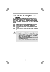
...of the advantageous transfer speed and the facilitating mobile capability, in the near future, eSATAII will replace USB 2.0 and IEEE 1394 to this motherboard, it is enabled. Therefore, on the market, the data transfer rate of the I /O shield, you may simply plug your SATAII ... mobility like USB. Then the bottom eSATAII port of USB 2.0 is up to the eSATAII ports instead of Hot Plug feature. This motherboard supports eSATAII interface, the external SATAII specification. For example, with a SATA data cable first. However, eSATAII provides the data transfer rate...
...of the advantageous transfer speed and the facilitating mobile capability, in the near future, eSATAII will replace USB 2.0 and IEEE 1394 to this motherboard, it is enabled. Therefore, on the market, the data transfer rate of the I /O shield, you may simply plug your SATAII ... mobility like USB. Then the bottom eSATAII port of USB 2.0 is up to the eSATAII ports instead of Hot Plug feature. This motherboard supports eSATAII interface, the external SATAII specification. For example, with a SATA data cable first. However, eSATAII provides the data transfer rate...

User Manual
Page 27
... ports of the I /O shield, you enable. see p.10 No.38) with another SATA data cable. If you plan to install two eSATAII devices to this motherboard, you need to connect eSATAII device and the eSATAII port of the I /O shield 27 see p.10 No.11) and the orange eSATAII connector (eSATAII_TOP;
... ports of the I /O shield, you enable. see p.10 No.38) with another SATA data cable. If you plan to install two eSATAII devices to this motherboard, you need to connect eSATAII device and the eSATAII port of the I /O shield 27 see p.10 No.11) and the orange eSATAII connector (eSATAII_TOP;
User Manual
Page 30
...RAID 0, RAID 1, or JBOD functions will guide you need to install at least 4 SATA / SATAII hard disks. If you plan to the motherboard's SATAII connector. If you need to install at least 2 SATA / SATAII hard disks. This section will be operated in BIOS setup. Please ... 1: Install the SATA / SATAII hard disks into the drive bays of your chassis. 2.11 Serial ATA (SATA) / Serial ATAII (SATAII) Hard Disks Installation This motherboard adopts ULi M1697 chipset that supports Serial ATA (SATA) / Serial ATAII (SATAII) hard disks and RAID (RAID 0, RAID 1, RAID 0+1, JBOD, and RAID 5)...
...RAID 0, RAID 1, or JBOD functions will guide you need to install at least 4 SATA / SATAII hard disks. If you plan to the motherboard's SATAII connector. If you need to install at least 2 SATA / SATAII hard disks. This section will be operated in BIOS setup. Please ... 1: Install the SATA / SATAII hard disks into the drive bays of your chassis. 2.11 Serial ATA (SATA) / Serial ATAII (SATAII) Hard Disks Installation This motherboard adopts ULi M1697 chipset that supports Serial ATA (SATA) / Serial ATAII (SATAII) hard disks and RAID (RAID 0, RAID 1, RAID 0+1, JBOD, and RAID 5)...

User Manual
Page 31
... removing the eSATAII device. 31 NOTE What is Hot Swap Function? 2.12 Hot Plug and Hot Swap Functions for SATA / SATAII HDDs and eSATAII Devices K8SLI-eSATA2 motherboard supports Hot Plug and Hot Swap functions for SATA / SATAII / eSATAII Devices in working condition. If the SATA / SATAII HDDs are built as Hot Plug...
... removing the eSATAII device. 31 NOTE What is Hot Swap Function? 2.12 Hot Plug and Hot Swap Functions for SATA / SATAII HDDs and eSATAII Devices K8SLI-eSATA2 motherboard supports Hot Plug and Hot Swap functions for SATA / SATAII / eSATAII Devices in working condition. If the SATA / SATAII HDDs are built as Hot Plug...
User Manual
Page 33
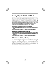
... XP, or Windows XP 64-bit OS installation. Start Windows 2000, windows XP, or Windows XP 64-bit OS installation. 2.15 Untied Overclocking Technology This motherboard supports Untied Overclocking Technology, which means during overclocking, but still keeping Hot Plug function, please choose AHCI mode. Therefore, CPU FSB is untied during overclocking...
... XP, or Windows XP 64-bit OS installation. Start Windows 2000, windows XP, or Windows XP 64-bit OS installation. 2.15 Untied Overclocking Technology This motherboard supports Untied Overclocking Technology, which means during overclocking, but still keeping Hot Plug function, please choose AHCI mode. Therefore, CPU FSB is untied during overclocking...

