
RAID Installation Guide
Page 1
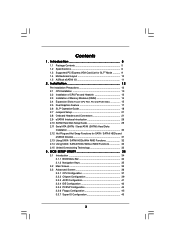
Guide to SATA Hard Disks Installation 2 1.1 Serial ATA (SATA) Hard Disks Installation 2 2. Guide to RAID Configurations 3 2.1 Introduction of RAID 3 2.2 RAID Configuration Precautions 5 2.3 Setting the BIOS RAID Items 6 2.4 Configuring ULi RAID BIOS 6 2.4.1 Main Menu 7 2.4.2 Drive Select Menu 10 2.4.3 RAID Array List 10 3. Using ULi Windows RAID Utility 11 3.1 How to Create RAID under Windows 11 3.2 How to Delete RAID under Windows 15 1 Guide to Migrate RAID under Windows 14 3.3 How to SATA Hard Disks Installation and RAID Configuration 1.
Guide to SATA Hard Disks Installation 2 1.1 Serial ATA (SATA) Hard Disks Installation 2 2. Guide to RAID Configurations 3 2.1 Introduction of RAID 3 2.2 RAID Configuration Precautions 5 2.3 Setting the BIOS RAID Items 6 2.4 Configuring ULi RAID BIOS 6 2.4.1 Main Menu 7 2.4.2 Drive Select Menu 10 2.4.3 RAID Array List 10 3. Using ULi Windows RAID Utility 11 3.1 How to Create RAID under Windows 11 3.2 How to Delete RAID under Windows 15 1 Guide to Migrate RAID under Windows 14 3.3 How to SATA Hard Disks Installation and RAID Configuration 1.
RAID Installation Guide
Page 6
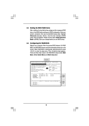
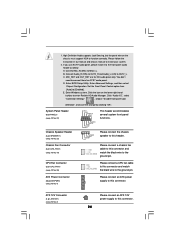
...SATAII_ORANGE 6 There are three major areas in the BIOS before you exit BIOS setup. 2.4 Configuring ULi RAID BIOS Reboot your RAID configuration. When RAID BIOS is waiting after identifying drives, press to enter the setup menu. 2.3 Setting the BIOS RAID Items After installing the hard disk drives, please... set the option SATA Operation Mode to enter BIOS setup utility. After the system BIOS detects ULi RAID BIOS, the RAID BIOS version and drive information shows up on the screen...
...SATAII_ORANGE 6 There are three major areas in the BIOS before you exit BIOS setup. 2.4 Configuring ULi RAID BIOS Reboot your RAID configuration. When RAID BIOS is waiting after identifying drives, press to enter the setup menu. 2.3 Setting the BIOS RAID Items After installing the hard disk drives, please... set the option SATA Operation Mode to enter BIOS setup utility. After the system BIOS detects ULi RAID BIOS, the RAID BIOS version and drive information shows up on the screen...

RAID Installation Guide
Page 9
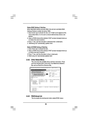
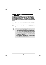
... ously defined RAID 1, 5 or 0+1 to key in the drives. 5. Use 'Enter' key to activate this item. Stripe Size This option is replaced or BIOS detects a broken RAID, the user can choose a stripe size from M to activate this item. An 'R' flashing cursor appears at the bottom of drives for ...the user to do drive copy. The source and target drives are indicated by 'M' and 'm' in a name for the user to perform rebuild. 2. BIOS shows the source (marked with 'M') and target (marked with 'm') drives. 3. Next the Array Name input line appears for the newly created array. The ...
... ously defined RAID 1, 5 or 0+1 to key in the drives. 5. Use 'Enter' key to activate this item. Stripe Size This option is replaced or BIOS detects a broken RAID, the user can choose a stripe size from M to activate this item. An 'R' flashing cursor appears at the bottom of drives for ...the user to do drive copy. The source and target drives are indicated by 'M' and 'm' in a name for the user to perform rebuild. 2. BIOS shows the source (marked with 'M') and target (marked with 'm') drives. 3. Next the Array Name input line appears for the newly created array. The ...
RAID Installation Guide
Page 10
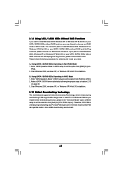
... RAID. 1. SATAII_BLUE SATAII_BLACK SATAII_RED SATAII_ORANGE 2.4.3 RAID Array List This list showa the existing and newly created RAID arrays. 10 Delete RAID Setting & Partition When RAID BIOS detects a broken RAID, the user can use Delete RAID Setting & Partition to activate this item. 2. 'Data on RAID drives will be deleted (Y/N)?' Press 'Enter' key...
... RAID. 1. SATAII_BLUE SATAII_BLACK SATAII_RED SATAII_ORANGE 2.4.3 RAID Array List This list showa the existing and newly created RAID arrays. 10 Delete RAID Setting & Partition When RAID BIOS detects a broken RAID, the user can use Delete RAID Setting & Partition to activate this item. 2. 'Data on RAID drives will be deleted (Y/N)?' Press 'Enter' key...
RAID Installation Guide
Page 11
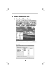
3. After the driver and utility are installed correctly, you can create RAID arrays in either the RAID BIOS setup menu as shown below, or find ULi RAID utility from Windows Program or click on 'Configuration' at task bar. ULi RAID Utility The information ...
3. After the driver and utility are installed correctly, you can create RAID arrays in either the RAID BIOS setup menu as shown below, or find ULi RAID utility from Windows Program or click on 'Configuration' at task bar. ULi RAID Utility The information ...
User Manual
Page 3
... (SATA) / Serial ATAII (SATAII) Hard Disks Installation 30 2.12 Hot Plug and Hot Swap Functions for SLITM Mode 9 1.4 Motherboard Layout 10 1.5 ASRock eSATAII I/O 11 2 . BIOS SETUP UTILITY 34 3.1 Introduction 34 3.1.1 BIOS Menu Bar 34 3.1.2 Navigation Keys 35 3.2 Main Screen 35 3.3 Advanced Screen 36 3.3.1 CPU Configuration 37 3.3.2 Chipset Configuration 39 3.3.3 ACPI Configuration 41 3.3.4 IDE...
... (SATA) / Serial ATAII (SATAII) Hard Disks Installation 30 2.12 Hot Plug and Hot Swap Functions for SLITM Mode 9 1.4 Motherboard Layout 10 1.5 ASRock eSATAII I/O 11 2 . BIOS SETUP UTILITY 34 3.1 Introduction 34 3.1.1 BIOS Menu Bar 34 3.1.2 Navigation Keys 35 3.2 Main Screen 35 3.3 Advanced Screen 36 3.3.1 CPU Configuration 37 3.3.2 Chipset Configuration 39 3.3.3 ACPI Configuration 41 3.3.4 IDE...

User Manual
Page 5
... guide to change without further notice. Introduction Thank you for purchasing ASRock K8SLI-eSATA2 motherboard, a reliable motherboard produced under ASRock's consistently stringent quality control. Because the motherboard specifications and the BIOS software might be updated, the content of this manual will be subject to BIOS setup and information of the motherboard and step-bystep guide to...
... guide to change without further notice. Introduction Thank you for purchasing ASRock K8SLI-eSATA2 motherboard, a reliable motherboard produced under ASRock's consistently stringent quality control. Because the motherboard specifications and the BIOS software might be updated, the content of this manual will be subject to BIOS setup and information of the motherboard and step-bystep guide to...

User Manual
Page 7
...Temperature Sensing - Microsoft® Windows® 2000 / XP / XP 64-bit compliant - Supports jumperfree - Chassis Fan Tachometer - Connector BIOS Feature Support CD Hardware Monitor OS Certifications - 4 x Serial ATAII 3.0Gb/s connectors, support RAID (RAID 0, 1, 0+1, JBOD, 5)... and "Hot Plug" functions (see CAUTION 6) - 2 x eSATAII 3.0Gb/s connectors (shared with 2 SATAII connectors), support "Hot Plug" function (see CAUTION 8) - 2Mb AMI BIOS - CD in header - Front panel audio connector - 2 x USB 2.0 headers (support 4 USB 2.0 ports) (see CAUTION 7) - 2 x ATA133 IDE connectors (support 4...
...Temperature Sensing - Microsoft® Windows® 2000 / XP / XP 64-bit compliant - Supports jumperfree - Chassis Fan Tachometer - Connector BIOS Feature Support CD Hardware Monitor OS Certifications - 4 x Serial ATAII 3.0Gb/s connectors, support RAID (RAID 0, 1, 0+1, JBOD, 5)... and "Hot Plug" functions (see CAUTION 6) - 2 x eSATAII 3.0Gb/s connectors (shared with 2 SATAII connectors), support "Hot Plug" function (see CAUTION 8) - 2Mb AMI BIOS - CD in header - Front panel audio connector - 2 x USB 2.0 headers (support 4 USB 2.0 ports) (see CAUTION 7) - 2 x ATA133 IDE connectors (support 4...
User Manual
Page 24
... clicking "OK". CPU Fan Connector (3-pin CPU_FAN1) (see p.10 No. 4) Please connect an ATX power supply to function correctly. Connect Mic_IN (MIC) to OUT2_L. Enter BIOS Setup Utility. Set the Front Panel Control option from [Auto] to install your system. 2. Please connect the chassis speaker to the ground pin. MIC_RET and...
... clicking "OK". CPU Fan Connector (3-pin CPU_FAN1) (see p.10 No. 4) Please connect an ATX power supply to function correctly. Connect Mic_IN (MIC) to OUT2_L. Enter BIOS Setup Utility. Set the Front Panel Control option from [Auto] to install your system. 2. Please connect the chassis speaker to the ground pin. MIC_RET and...
User Manual
Page 30
... that supports Serial ATA (SATA) / Serial ATAII (SATAII) hard disks and RAID (RAID 0, RAID 1, RAID 0+1, JBOD, and RAID 5) functions. This section will be operated in BIOS setup. "RAID" and "non-RAID" mode are options under "SATA Operation Mode" in "RAID" mode. 3.
... that supports Serial ATA (SATA) / Serial ATAII (SATAII) hard disks and RAID (RAID 0, RAID 1, RAID 0+1, JBOD, and RAID 5) functions. This section will be operated in BIOS setup. "RAID" and "non-RAID" mode are options under "SATA Operation Mode" in "RAID" mode. 3.
User Manual
Page 33
... / SATAII HDDs without RAID functions but PCI and PCIE buses are allowed to choose non-RAID mode or AHCI mode. Enter "SATA Operation Mode" in BIOS setup to set the option from [RAID] to [non- 2.14 Using SATA / SATAII HDDs Without RAID Functions If you want to install Windows 2000, ... means during overclocking, but still keeping Hot Plug function, please choose AHCI mode. Please follow the below procedures for selecting the mode you are in BIOS setup to set the option from [Auto] to install Windows 2000, Windows XP, or Windows XP 64-bit OS on page 32. 3. Therefore, CPU FSB...
... / SATAII HDDs without RAID functions but PCI and PCIE buses are allowed to choose non-RAID mode or AHCI mode. Enter "SATA Operation Mode" in BIOS setup to set the option from [RAID] to [non- 2.14 Using SATA / SATAII HDDs Without RAID Functions If you want to install Windows 2000, ... means during overclocking, but still keeping Hot Plug function, please choose AHCI mode. Please follow the below procedures for selecting the mode you are in BIOS setup to set the option from [Auto] to install Windows 2000, Windows XP, or Windows XP 64-bit OS on page 32. 3. Therefore, CPU FSB...
User Manual
Page 34
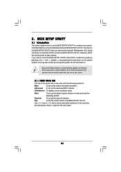
... the reset button on . If you start up the security features Exit To exit the current screen or the BIOS SETUP UTILITY Use < > key or < > key to enter the BIOS SETUP UTILITY after POST, restart the system by pressing + + , or by turning the system off and then... back on the system chassis. BIOS SETUP UTILITY 3.1 Introduction This section explains how to use the BIOS SETUP UTILITY to enter the BIOS SETUP UTILITY, otherwise, POST will continue with the following BIOS setup screens and descriptions are for reference purpose only, and they may...
... the reset button on . If you start up the security features Exit To exit the current screen or the BIOS SETUP UTILITY Use < > key or < > key to enter the BIOS SETUP UTILITY after POST, restart the system by pressing + + , or by turning the system off and then... back on the system chassis. BIOS SETUP UTILITY 3.1 Introduction This section explains how to use the BIOS SETUP UTILITY to enter the BIOS SETUP UTILITY, otherwise, POST will continue with the following BIOS setup screens and descriptions are for reference purpose only, and they may...
User Manual
Page 35
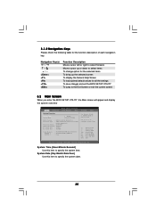
... this item to specify the system date. 35 3.1.2 Navigation Keys Please check the following table for all the settings To save changes and exit the BIOS SETUP UTILITY To jump to the Exit Screen or exit the current screen 3.2 Main Screen When you enter the... UTILITY H/W Monitor Boot System Overview System Time System Date [17:00:09] [Thu 01/19/2006] BIOS Version : K8SLI-eSATA2 BIOS P1.0 Processor Type : AMD Athlon(tm) 64 Processor 3500+ (64 bit supported) Processor Speed : 2200 MHz Microcode Update : 10FF0/41 L1 Cache Size : 128KB L2 ...
... this item to specify the system date. 35 3.1.2 Navigation Keys Please check the following table for all the settings To save changes and exit the BIOS SETUP UTILITY To jump to the Exit Screen or exit the current screen 3.2 Main Screen When you enter the... UTILITY H/W Monitor Boot System Overview System Time System Date [17:00:09] [Thu 01/19/2006] BIOS Version : K8SLI-eSATA2 BIOS P1.0 Processor Type : AMD Athlon(tm) 64 Processor 3500+ (64 bit supported) Processor Speed : 2200 MHz Microcode Update : 10FF0/41 L1 Cache Size : 128KB L2 ...

User Manual
Page 36
Main BIOS SETUP UTILITY Advanced H/W Monitor Boot Security Exit Advanced Settings WARNING : Setting wrong values in this section may cause the system to AMD 939-Pin CPU or 940PinCPU (AM2) by installing an add-on ASRock 939CPU Board or AM2CPU Board intofuture CPU Port on this motherboard. 3.3 Advanced Screen In this section, you...
Main BIOS SETUP UTILITY Advanced H/W Monitor Boot Security Exit Advanced Settings WARNING : Setting wrong values in this section may cause the system to AMD 939-Pin CPU or 940PinCPU (AM2) by installing an add-on ASRock 939CPU Board or AM2CPU Board intofuture CPU Port on this motherboard. 3.3 Advanced Screen In this section, you...
User Manual
Page 37
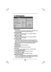
.... The range is from 90MHz to adjust PCI frequency. Boot Failure Guard Enable or disable the feature of Processor Multiplier and Processor Voltage. 3.3.1 CPU Configuration BIOS SETUP UTILITY Advanced CPU Configuration Overclock Mode CPU Frequency (MHz) PCIE Frequency (MHz) Spread Spectrum Boot Failure Guard Cool' n' Quiet Processor Maximum Multiplier Processor Maximum...
.... The range is from 90MHz to adjust PCI frequency. Boot Failure Guard Enable or disable the feature of Processor Multiplier and Processor Voltage. 3.3.1 CPU Configuration BIOS SETUP UTILITY Advanced CPU Configuration Overclock Mode CPU Frequency (MHz) PCIE Frequency (MHz) Spread Spectrum Boot Failure Guard Cool' n' Quiet Processor Maximum Multiplier Processor Maximum...
User Manual
Page 38
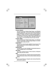
...the means of memory accessing. Memory Clock This item can set one of "Processor Maximum Multiplier". TRP Use this item. BIOS SETUP UTILITY Processor Multiplier This item will show when "Multiplier/Voltage Change" is set to a value higher than the value ... options: [Auto], [5CLK], [6CLK], [7CLK], [8CLK], [9CLK], [10CLK], [11CLK], [12CLK], [13CLK], [14CLK], and [15CLK]. Advanced BIOS SETUP UTILITY BIOS SETUP UTILITY CPU Configuration Overclock Mode CPU Frequency (MHz) PCIE Frequency (MHz) Spread Spectrum Boot Failure Guard Cool' n' Quiet Processor Maximum Multiplier Processor Maximum...
...the means of memory accessing. Memory Clock This item can set one of "Processor Maximum Multiplier". TRP Use this item. BIOS SETUP UTILITY Processor Multiplier This item will show when "Multiplier/Voltage Change" is set to a value higher than the value ... options: [Auto], [5CLK], [6CLK], [7CLK], [8CLK], [9CLK], [10CLK], [11CLK], [12CLK], [13CLK], [14CLK], and [15CLK]. Advanced BIOS SETUP UTILITY BIOS SETUP UTILITY CPU Configuration Overclock Mode CPU Frequency (MHz) PCIE Frequency (MHz) Spread Spectrum Boot Failure Guard Cool' n' Quiet Processor Maximum Multiplier Processor Maximum...
User Manual
Page 39
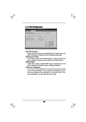
...]. The default value is [Auto]. NB Link Speed CPU - If you to adjust TRCD values. The default value is [Disabled]. 3.3.2 Chipset Configuration Advanced Chipset Settings BIOS SETUP UTILITY OnBoard LAN OnBoard HD Audio Front Panel Control [Enabled] [Auto] [Auto] Primary Graphics Adapter CPU - Bank Interleaving Interleaving allows memory accesses to be...
...]. The default value is [Auto]. NB Link Speed CPU - If you to adjust TRCD values. The default value is [Disabled]. 3.3.2 Chipset Configuration Advanced Chipset Settings BIOS SETUP UTILITY OnBoard LAN OnBoard HD Audio Front Panel Control [Enabled] [Auto] [Auto] Primary Graphics Adapter CPU - Bank Interleaving Interleaving allows memory accesses to be...

User Manual
Page 41
... ESC Select Screen Select Item Change Option General Help Load Defaults Save and Exit Exit v02.54 (C) Copyright 1985-2003, American Megatrends, Inc. 3.3.3 ACPI Configuration BIOS SETUP UTILITY Advanced ACPI Settings Suspend To RAM Repost Video on STR Resume Restore on the system from the power-soft-off mode. Ring-In...
... ESC Select Screen Select Item Change Option General Help Load Defaults Save and Exit Exit v02.54 (C) Copyright 1985-2003, American Megatrends, Inc. 3.3.3 ACPI Configuration BIOS SETUP UTILITY Advanced ACPI Settings Suspend To RAM Repost Video on STR Resume Restore on the system from the power-soft-off mode. Ring-In...
User Manual
Page 42
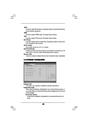
3.3.4 IDE Configuration BIOS SETUP UTILITY Advanced IDE Configuration Serial ATA Controller SATA Operation Mode eSATAII Support Primary IDE Master Primary IDE Slave Secondary IDE Master Secondary IDE Slave [...
3.3.4 IDE Configuration BIOS SETUP UTILITY Advanced IDE Configuration Serial ATA Controller SATA Operation Mode eSATAII Support Primary IDE Master Primary IDE Slave Secondary IDE Master Secondary IDE Slave [...

User Manual
Page 43
...device that you specify. LBA/Large Mode Use this item to select the LBA/Large mode for a hard disk > 512 MB under DOS and Windows; BIOS SETUP UTILITY Advanced Primary IDE Master Device Vendor Size LBA Mode Block Mode PIO Mode Async DMA Ultra DMA S.M.A.R.T. :Hard Disk :MAXTOR 6L080J4 :80.0 GB...data-integrity for IDE ARMD (ATAPI Removable Media Device), such as FDISK, to disable the LBA/Large mode. After selecting the hard disk information into BIOS, use of the Primary IDE hard disk drives to automatically detect the hard disk drive. Make sure to set the PIO mode to the system...
...device that you specify. LBA/Large Mode Use this item to select the LBA/Large mode for a hard disk > 512 MB under DOS and Windows; BIOS SETUP UTILITY Advanced Primary IDE Master Device Vendor Size LBA Mode Block Mode PIO Mode Async DMA Ultra DMA S.M.A.R.T. :Hard Disk :MAXTOR 6L080J4 :80.0 GB...data-integrity for IDE ARMD (ATAPI Removable Media Device), such as FDISK, to disable the LBA/Large mode. After selecting the hard disk information into BIOS, use of the Primary IDE hard disk drives to automatically detect the hard disk drive. Make sure to set the PIO mode to the system...


