
User Manual
Page 3
...174; VistaTM Basic Logo 9 1.4 Motherboard Layout 10 1.5 HD 8CH I/O 11 2 . Installation 12 Pre-installation Precautions 12 2.1 CPU Installation 13 2.2 Installation of CPU Fan and Heatsink 13 2.3 Installation of Memory Modules (DIMM 14 2.4 Expansion Slots (PCI, PCI Express, and HDMR Slots 15 ...Introduction 24 3.1.1 BIOS Menu Bar 24 3.1.2 Navigation Keys 25 3.2 Main Screen 25 3.3 Advanced Screen 26 3.3.1 CPU Configuration 26 3.3.2 Chipset Configuration 29 3.3.3 ACPI Configuration 30 3.3.4 IDE Configuration 31 3.3.5 PCIPnP Configuration 33 3.3.6 Floppy Configuration 34 3
...174; VistaTM Basic Logo 9 1.4 Motherboard Layout 10 1.5 HD 8CH I/O 11 2 . Installation 12 Pre-installation Precautions 12 2.1 CPU Installation 13 2.2 Installation of CPU Fan and Heatsink 13 2.3 Installation of Memory Modules (DIMM 14 2.4 Expansion Slots (PCI, PCI Express, and HDMR Slots 15 ...Introduction 24 3.1.1 BIOS Menu Bar 24 3.1.2 Navigation Keys 25 3.2 Main Screen 25 3.3 Advanced Screen 26 3.3.1 CPU Configuration 26 3.3.2 Chipset Configuration 29 3.3.3 ACPI Configuration 30 3.3.4 IDE Configuration 31 3.3.5 PCIPnP Configuration 33 3.3.6 Floppy Configuration 34 3

User Manual
Page 5
...) 1 x ASRock K8NF4G-VSTA Quick Installation Guide 1 x ASRock K8NF4G-VSTA Support CD 1 x Ultra ATA 66/100/133 IDE Ribbon Cable (80-conductor) 1 x 3.5-in Floppy Drive Ribbon Cable 1 x Serial ATA (SATA) Data Cable (Optional) 1 x Serial ATA (SATA) HDD Power Cable (Optional) 1 x HD 8CH I/O Shield 1 x COM Port Bracket 1 x HDMR Card (Optional) 5 You may find the latest VGA cards and CPU...
...) 1 x ASRock K8NF4G-VSTA Quick Installation Guide 1 x ASRock K8NF4G-VSTA Support CD 1 x Ultra ATA 66/100/133 IDE Ribbon Cable (80-conductor) 1 x 3.5-in Floppy Drive Ribbon Cable 1 x Serial ATA (SATA) Data Cable (Optional) 1 x Serial ATA (SATA) HDD Power Cable (Optional) 1 x HD 8CH I/O Shield 1 x COM Port Bracket 1 x HDMR Card (Optional) 5 You may find the latest VGA cards and CPU...

User Manual
Page 6
...-bit AMD AthlonTM 64 and 32-bit/64-bit Sempron Processors - Supports AMD's Cool 'n' QuietTM Technology (see CAUTION 2) - Realtek PHY RTL8201CL - ASRock U-COP (see CAUTION 3) - shared memory 128MB - 1.2 Specifications Platform CPU Chipset Memory Hybrid Booster Expansion Slot Graphics Audio LAN Rear Panel I /O - 1 x PS/2 Mouse - 1 x PS/2 Keyboard Port - 1 x VGA Port - 1 x Parallel Port (ECP...
...-bit AMD AthlonTM 64 and 32-bit/64-bit Sempron Processors - Supports AMD's Cool 'n' QuietTM Technology (see CAUTION 2) - Realtek PHY RTL8201CL - ASRock U-COP (see CAUTION 3) - shared memory 128MB - 1.2 Specifications Platform CPU Chipset Memory Hybrid Booster Expansion Slot Graphics Audio LAN Rear Panel I /O - 1 x PS/2 Mouse - 1 x PS/2 Keyboard Port - 1 x VGA Port - 1 x Parallel Port (ECP...
User Manual
Page 7
... 1, JBOD (No support for "Hot Plug" function) (see CAUTION 8) - Supports "Plug and Play" - ACPI 1.1 Compliance Wake Up Events - CPU Overheat Shutdown to Protect CPU Life - Microsoft® Windows® 2000 / XP / XP 64-bit / VistaTM compliant (see CAUTION 6) - 2 x ATA133 IDE connectors (support...1 x Floppy connector - 1 x IR header - 1 x Game header - 1 x COM port header - FCC, CE, WHQL 7 Supports jumperfree - CPU Temperature Sensing - Chassis Fan Tachometer - CD in header - Front panel audio connector - 2 x USB 2.0 headers (support 4 USB 2.0 ports) (see CAUTION 7) - 4Mb AMI ...
... 1, JBOD (No support for "Hot Plug" function) (see CAUTION 8) - Supports "Plug and Play" - ACPI 1.1 Compliance Wake Up Events - CPU Overheat Shutdown to Protect CPU Life - Microsoft® Windows® 2000 / XP / XP 64-bit / VistaTM compliant (see CAUTION 6) - 2 x ATA133 IDE connectors (support...1 x Floppy connector - 1 x IR header - 1 x Game header - 1 x COM port header - FCC, CE, WHQL 7 Supports jumperfree - CPU Temperature Sensing - Chassis Fan Tachometer - CD in header - Front panel audio connector - 2 x USB 2.0 headers (support 4 USB 2.0 ports) (see CAUTION 7) - 4Mb AMI ...
User Manual
Page 8
... ASRock website http://www.asrock.com 8 This motherboard supports Untied Overclocking Technology. Although this motherboard offers stepless control, it is detected, the system will update it back again. Frequencies other than the recommended CPU bus frequencies may cause the instability of the system or damage the CPU. 4. While CPU overheat...hard disk (from SATAII 3Gb/s down to our website in the future. Besides, you resume the system, please check if the CPU fan on the motherboard functions properly and unplug the power cord, then plug it to SATA 1.5Gb/s), and connect it is not ready...
... ASRock website http://www.asrock.com 8 This motherboard supports Untied Overclocking Technology. Although this motherboard offers stepless control, it is detected, the system will update it back again. Frequencies other than the recommended CPU bus frequencies may cause the instability of the system or damage the CPU. 4. While CPU overheat...hard disk (from SATAII 3Gb/s down to our website in the future. Besides, you resume the system, please check if the CPU fan on the motherboard functions properly and unplug the power cord, then plug it to SATA 1.5Gb/s), and connect it is not ready...
User Manual
Page 9
... be adjusted up to submit Windows® VistaTM Basic logo, please follow the below table for minimum hardware requirement. Please adopt the CPU, memory, and VGA that we suggest. CPU Memory VGA Sempron 2500+ 512MB Single Channel* DX9.0 with WDDM Driver * If you use onboard VGA with total system memory size above...
... be adjusted up to submit Windows® VistaTM Basic logo, please follow the below table for minimum hardware requirement. Please adopt the CPU, memory, and VGA that we suggest. CPU Memory VGA Sempron 2500+ 512MB Single Channel* DX9.0 with WDDM Driver * If you use onboard VGA with total system memory size above...

User Manual
Page 13
...(CPU_FAN1, see Page 10, No. 30). The lever clicks on the socket while you install the CPU into this motherboard, it is locked. Position the CPU directly above the socket such that the CPU and the heatsink are securely fastened and in good contact with a small triangle. Step 3. Make sure... up to improve heat dissipation. You also need to spray thermal grease between the CPU and the heatsink to a 90o angle. Then connect the CPU fan to secure the CPU. The CPU fits only in place. When the CPU is necessary to install a larger heatsink and cooling fan to dissipate heat. Step ...
...(CPU_FAN1, see Page 10, No. 30). The lever clicks on the socket while you install the CPU into this motherboard, it is locked. Position the CPU directly above the socket such that the CPU and the heatsink are securely fastened and in good contact with a small triangle. Step 3. Make sure... up to improve heat dissipation. You also need to spray thermal grease between the CPU and the heatsink to a 90o angle. Then connect the CPU fan to secure the CPU. The CPU fits only in place. When the CPU is necessary to install a larger heatsink and cooling fan to dissipate heat. Step ...

User Manual
Page 19
... it is installed. Failing to this connector. Please connect an ATX power supply to do so will cause power up failure. Please connect the CPU fan cable to this connector and match the black wire to the ground pin. Chassis Fan Connector (3-pin CHA_FAN1) (see p.9 No. 14)... GND +12V CHA_FAN_SPEED CPU Fan Connector (4-pin CPU_FAN1) (see p.9 No. 30) FAN_SPEED_CONTROL CPU_FAN_SPEED +12V GND ATX Power Connector (20-pin ATXPWR1) (see p.9 No. 16) PLED+ PLEDPWRBTN#...
... it is installed. Failing to this connector. Please connect an ATX power supply to do so will cause power up failure. Please connect the CPU fan cable to this connector and match the black wire to the ground pin. Chassis Fan Connector (3-pin CHA_FAN1) (see p.9 No. 14)... GND +12V CHA_FAN_SPEED CPU Fan Connector (4-pin CPU_FAN1) (see p.9 No. 30) FAN_SPEED_CONTROL CPU_FAN_SPEED +12V GND ATX Power Connector (20-pin ATXPWR1) (see p.9 No. 16) PLED+ PLEDPWRBTN#...
User Manual
Page 23
At the beginning of BIOS setup to set the selection from [Auto] to [CPU, PCIE, Async.]. NOTE. Please refer to the document in the Support CD, "Guide to nVidia RAID Utility for Windows", which is located in the folder... Guide 2.14 Untied Overclocking Technology This motherboard supports Untied Overclocking Technology, which is untied during overclocking, FSB enjoys better margin due to [RAID] first. Therefore, CPU FSB is located in the folder at the following path: .. \Information\Manual\RAID Installation Guide After step1, 2, 3, you can operate under a more stable overclocking ...
At the beginning of BIOS setup to set the selection from [Auto] to [CPU, PCIE, Async.]. NOTE. Please refer to the document in the Support CD, "Guide to nVidia RAID Utility for Windows", which is located in the folder... Guide 2.14 Untied Overclocking Technology This motherboard supports Untied Overclocking Technology, which is untied during overclocking, FSB enjoys better margin due to [RAID] first. Therefore, CPU FSB is located in the folder at the following path: .. \Information\Manual\RAID Installation Guide After step1, 2, 3, you can operate under a more stable overclocking ...

User Manual
Page 26
... Screen In this section may cause the system to malfunction. 3.3.1 CPU Configuration BIOS SETUP UTILITY Advanced CPU Configuration Overclock Mode CPU Frequency (MHz) PCIE Frequency (MHz) Boot Failure Guard CPU Spread Spectrum PCIE Spread Spectrum SATA Spread Spectrum HT Spread Spectrum Cool...Configuration, IDE Configuration, PCIPnP Configuration, Floppy Configuration, SuperIO Configuration, and USB Configuration. Cnfiguration options: [Auto], [CPU, PCIE, Sync.] and [CPU, PCIE, Async.]. The default value is [200]. 26 Main BIOS SETUP UTILITY Advanced H/W Monitor Boot Security...
... Screen In this section may cause the system to malfunction. 3.3.1 CPU Configuration BIOS SETUP UTILITY Advanced CPU Configuration Overclock Mode CPU Frequency (MHz) PCIE Frequency (MHz) Boot Failure Guard CPU Spread Spectrum PCIE Spread Spectrum SATA Spread Spectrum HT Spread Spectrum Cool...Configuration, IDE Configuration, PCIPnP Configuration, Floppy Configuration, SuperIO Configuration, and USB Configuration. Cnfiguration options: [Auto], [CPU, PCIE, Sync.] and [CPU, PCIE, Async.]. The default value is [200]. 26 Main BIOS SETUP UTILITY Advanced H/W Monitor Boot Security...

User Manual
Page 27
... Megatrends, Inc. 27 Configuration options: [Disabled], and [Enabled]. BIOS SETUP UTILITY Advanced CPU Configuration Overclock Mode CPU Frequency (MHz) PCIE Frequency (MHz) Boot Failure Guard CPU Spread Spectrum PCIE Spread Spectrum SATA Spread Spectrum HT Spread Spectrum Cool' n' Quiet Processor ...[Disabled] [Auto] [4 Beats] If AUTO, multiplier and voltage will be set to [Enabled] as default. The range is [100]. CPU Spread Spectrum This feature will display Processor Maximum Voltage for reference. Processor Maximum Voltage It will be set to [Center Spread] as default. ...
... Megatrends, Inc. 27 Configuration options: [Disabled], and [Enabled]. BIOS SETUP UTILITY Advanced CPU Configuration Overclock Mode CPU Frequency (MHz) PCIE Frequency (MHz) Boot Failure Guard CPU Spread Spectrum PCIE Spread Spectrum SATA Spread Spectrum HT Spread Spectrum Cool' n' Quiet Processor ...[Disabled] [Auto] [4 Beats] If AUTO, multiplier and voltage will be set to [Enabled] as default. The range is [100]. CPU Spread Spectrum This feature will display Processor Maximum Voltage for reference. Processor Maximum Voltage It will be set to [Center Spread] as default. ...

User Manual
Page 29
...Settings Onboard LAN Onboard HD Audio Front Panel Controller Share Memory Primary Graphics Adapter [Enabled] [Auto] [Auto] [Auto] [PCI] CPU-NB Link Speed CPU-NB Kink Width NB-SB Link Speed [Auto] [Auto] [Auto] DRAM Voltage [Auto] To set share memory feature. OnBoard HD...American Megatrends, Inc. The default value is plugged. Front Panel Control Select [Auto], [Enabled] or [Disabled] for the onboard HD Audio feature. CPU - DRAM Voltage Use this feature is [Auto]. Configuration options: [Auto], [8 bit], and [16 bit]. SB Link Speed This feature allows you ...
...Settings Onboard LAN Onboard HD Audio Front Panel Controller Share Memory Primary Graphics Adapter [Enabled] [Auto] [Auto] [Auto] [PCI] CPU-NB Link Speed CPU-NB Kink Width NB-SB Link Speed [Auto] [Auto] [Auto] DRAM Voltage [Auto] To set share memory feature. OnBoard HD...American Megatrends, Inc. The default value is plugged. Front Panel Control Select [Auto], [Enabled] or [Disabled] for the onboard HD Audio feature. CPU - DRAM Voltage Use this feature is [Auto]. Configuration options: [Auto], [8 bit], and [16 bit]. SB Link Speed This feature allows you ...

User Manual
Page 36
..., Inc. if there is no USB device connected, "Auto" option will start to emulate the I/O devices of the CPU temperature, motherboard temperature, CPU fan speed, chassis fan speed, and the critical voltage. Or you to enable or disable the use of USB controller.... item to enable or disable the support to auto-detect; etc. BIOS SETUP UTILITY Main Advanced H/W Monitor Boot Security Exit Hardware Health Event Monitoring CPU Temperature M / B Temperature CPU Fan Speed Chassis Fan Speed Vcore + 3.30V + 5.00V + 12.00V : 37 C / 98 F : 31 C / 87 F : 2833 RPM : N/A : 1.532 V : 3.129 V ...
..., Inc. if there is no USB device connected, "Auto" option will start to emulate the I/O devices of the CPU temperature, motherboard temperature, CPU fan speed, chassis fan speed, and the critical voltage. Or you to enable or disable the use of USB controller.... item to enable or disable the support to auto-detect; etc. BIOS SETUP UTILITY Main Advanced H/W Monitor Boot Security Exit Hardware Health Event Monitoring CPU Temperature M / B Temperature CPU Fan Speed Chassis Fan Speed Vcore + 3.30V + 5.00V + 12.00V : 37 C / 98 F : 31 C / 87 F : 2833 RPM : N/A : 1.532 V : 3.129 V ...

Quick Installation Guide
Page 2
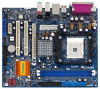
Motherboard Layout English 1 PS2_USB_PW1 Jumper 16 Chassis Speaker Header (SPEAKER 1) 2 ATX 12V Power Connector (ATX12V1) 17 USB 2.0 Header (USB67, Blue) 3 754-Pin CPU Socket 18 Infrared Module Header (IR1) 4 CPU Heatsink Retention Module 19 USB 2.0 Header (USB45, Blue) 5 184-pin DDR DIMM Slots (DDR1- 2) 20 Floppy Connector (FLOPPY1) 6 Secondary IDE Connector (... (SATAII_1, red) 28 ATX Power Connector (ATXPWR1) 14 Chassis Fan Connector (CHA_FAN1) 29 Serial Port Connector (COM1) 15 System Panel Header (PANEL1) 30 CPU Fan Connector (CPU_FAN1) 2 ASRock K8NF4G-VSTA Motherboard
Motherboard Layout English 1 PS2_USB_PW1 Jumper 16 Chassis Speaker Header (SPEAKER 1) 2 ATX 12V Power Connector (ATX12V1) 17 USB 2.0 Header (USB67, Blue) 3 754-Pin CPU Socket 18 Infrared Module Header (IR1) 4 CPU Heatsink Retention Module 19 USB 2.0 Header (USB45, Blue) 5 184-pin DDR DIMM Slots (DDR1- 2) 20 Floppy Connector (FLOPPY1) 6 Secondary IDE Connector (... (SATAII_1, red) 28 ATX Power Connector (ATXPWR1) 14 Chassis Fan Connector (CHA_FAN1) 29 Serial Port Connector (COM1) 15 System Panel Header (PANEL1) 30 CPU Fan Connector (CPU_FAN1) 2 ASRock K8NF4G-VSTA Motherboard
Quick Installation Guide
Page 4
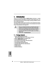
...be available on ASRock website as well. It delivers excellent performance with robust design conforming to ASRock's commitment to change without further notice. You may find the latest VGA cards and CPU support lists on ASRock website without notice... content of the motherboard and step-bystep installation guide. 1. ASRock website http://www.asrock.com 1.1 Package Contents 1 x ASRock K8NF4G-VSTA Motherboard (Micro ATX Form Factor: 9.6-in x 8.0-in, 24.4 cm x 20.3 cm) 1 x ASRock K8NF4G-VSTA Quick Installation Guide 1 x ASRock K8NF4G-VSTA Support CD 1 x Ultra ATA 66/100/133 IDE Ribbon...
...be available on ASRock website as well. It delivers excellent performance with robust design conforming to ASRock's commitment to change without further notice. You may find the latest VGA cards and CPU support lists on ASRock website without notice... content of the motherboard and step-bystep installation guide. 1. ASRock website http://www.asrock.com 1.1 Package Contents 1 x ASRock K8NF4G-VSTA Motherboard (Micro ATX Form Factor: 9.6-in x 8.0-in, 24.4 cm x 20.3 cm) 1 x ASRock K8NF4G-VSTA Quick Installation Guide 1 x ASRock K8NF4G-VSTA Support CD 1 x Ultra ATA 66/100/133 IDE Ribbon...

Quick Installation Guide
Page 5
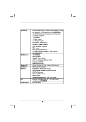
....3 cm - 754-Pin Socket Supporting advanced 64-bit AMD AthlonTM 64 and 32-bit/64-bit Sempron Processors - capacity: 2GB - Realtek PHY RTL8201CL - 1.2 Specifications Platform CPU Chipset Memory Hybrid Booster Expansion Slot Graphics Audio LAN Rear Panel I /O - 1 x PS/2 Mouse - 1 x PS/2 Keyboard Port - 1 x VGA Port - 1 x Parallel Port (ECP/EPP ...x PCI slots - 1 x PCI Express x 16 slot - 1 x PCI Express x 1 slot - 1 x HDMR slot - Micro ATX Form Factor: 9.6-in x 8.0-in /Front Speaker/Microphone (see CAUTION 5) English 5 ASRock K8NF4G-VSTA Motherboard ASRock U-COP (see CAUTION 1) -
....3 cm - 754-Pin Socket Supporting advanced 64-bit AMD AthlonTM 64 and 32-bit/64-bit Sempron Processors - capacity: 2GB - Realtek PHY RTL8201CL - 1.2 Specifications Platform CPU Chipset Memory Hybrid Booster Expansion Slot Graphics Audio LAN Rear Panel I /O - 1 x PS/2 Mouse - 1 x PS/2 Keyboard Port - 1 x VGA Port - 1 x Parallel Port (ECP/EPP ...x PCI slots - 1 x PCI Express x 16 slot - 1 x PCI Express x 1 slot - 1 x HDMR slot - Micro ATX Form Factor: 9.6-in x 8.0-in /Front Speaker/Microphone (see CAUTION 5) English 5 ASRock K8NF4G-VSTA Motherboard ASRock U-COP (see CAUTION 1) -

Quick Installation Guide
Page 6
...headers (support 4 USB 2.0 ports) (see CAUTION 8) - AMI Legal BIOS - Supports jumperfree - CPU Overheat Shutdown to Protect CPU Life - FCC, CE, WHQL English 6 ASRock K8NF4G-VSTA Motherboard CPU/Chassis FAN connector - 20 pin ATX power connector - 4 pin 12V power connector - Supports "Plug...- 4Mb AMI BIOS - Drivers, Utilities, AntiVirus Software (Trial Version) - Motherboard Temperature Sensing - SMBIOS 2.3.1 Support - CPU Fan Tachometer - CPU Quiet Fan - Connector BIOS Feature Support CD Hardware Monitor OS Certifications - 2 x Serial ATAII 3.0Gb/s connectors, support ...
...headers (support 4 USB 2.0 ports) (see CAUTION 8) - AMI Legal BIOS - Supports jumperfree - CPU Overheat Shutdown to Protect CPU Life - FCC, CE, WHQL English 6 ASRock K8NF4G-VSTA Motherboard CPU/Chassis FAN connector - 20 pin ATX power connector - 4 pin 12V power connector - Supports "Plug...- 4Mb AMI BIOS - Drivers, Utilities, AntiVirus Software (Trial Version) - Motherboard Temperature Sensing - SMBIOS 2.3.1 Support - CPU Fan Tachometer - CPU Quiet Fan - Connector BIOS Feature Support CD Hardware Monitor OS Certifications - 2 x Serial ATAII 3.0Gb/s connectors, support ...

Quick Installation Guide
Page 7
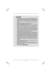
... is not ready yet. For audio output, this motherboard supports both stereo and mono modes. ASRock website http://www.asrock.com 7 ASRock K8NF4G-VSTA Motherboard English Since not all K8 754-pin CPU can also connect SATA hard disk to our website in the Support CD to SATAII mode. See APPENDIX on page 3 for details. 3. CAUTION...
... is not ready yet. For audio output, this motherboard supports both stereo and mono modes. ASRock website http://www.asrock.com 7 ASRock K8NF4G-VSTA Motherboard English Since not all K8 754-pin CPU can also connect SATA hard disk to our website in the Support CD to SATAII mode. See APPENDIX on page 3 for details. 3. CAUTION...

Quick Installation Guide
Page 8
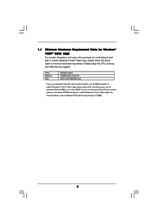
English 8 ASRock K8NF4G-VSTA Motherboard If you use onboard VGA with total system memory size 512MB and plan to submit Windows® VistaTM Basic logo, please adjust the shared memory size of onboard VGA can be adjusted up to 64MB or less than 64MB. CPU Memory VGA Sempron 2500+ 512MB Single ...size above 512MB and plan to submit Windows® VistaTM Basic logo, the shared memory size of onboard VGA to 128MB. Please adopt the CPU, memory, and VGA that we suggest. 1.3 Minimum Hardware Requirement Table for Windows® VistaTM Basic Logo For system integrators and users who...
English 8 ASRock K8NF4G-VSTA Motherboard If you use onboard VGA with total system memory size 512MB and plan to submit Windows® VistaTM Basic logo, please adjust the shared memory size of onboard VGA can be adjusted up to 64MB or less than 64MB. CPU Memory VGA Sempron 2500+ 512MB Single ...size above 512MB and plan to submit Windows® VistaTM Basic logo, the shared memory size of onboard VGA to 128MB. Please adopt the CPU, memory, and VGA that we suggest. 1.3 Minimum Hardware Requirement Table for Windows® VistaTM Basic Logo For system integrators and users who...

Quick Installation Guide
Page 9
... clicks on the carpet or the like. Also remember to a 90° angle. Position the CPU directly above the socket such that comes with a small triangle. English 9 ASRock K8NF4G-VSTA Motherboard Doing so may cause severe damage to secure the CPU. Step 4. 2. Unlock the socket by the edges and do so may damage the motherboard...
... clicks on the carpet or the like. Also remember to a 90° angle. Position the CPU directly above the socket such that comes with a small triangle. English 9 ASRock K8NF4G-VSTA Motherboard Doing so may cause severe damage to secure the CPU. Step 4. 2. Unlock the socket by the edges and do so may damage the motherboard...


