
User Manual
Page 3
...Menu 21 3.3 Advanced, Security, Power, Boot, and Exit Menus 23 4. Advanced BIOS Setup Menu 25 2. Introduction 4 1.1 Package Contents 4 1.2 Specifications 5 1.3 Motherboard Layout 7 1.4 ASRock I/O Plus 8 TM ...2. Exit Menu 33 3 Contents 1. Software Support 24 4.1 Install Operating System 24 4.2 Support CD Information 24 4.2.1 Running Support CD 24 4.2.2 Drivers Menu 24 ...DIMM 11 2.4 Expansion Slots (PCI and AGP Slots 12 2.5 Jumpers Setup 13 2.6 Onboard Headers and Connectors 15 2.7 Serial ATA (SATA) Hard Disks Installation 18 2.8 Hot Plug and Hot Swap Functions for...
...Menu 21 3.3 Advanced, Security, Power, Boot, and Exit Menus 23 4. Advanced BIOS Setup Menu 25 2. Introduction 4 1.1 Package Contents 4 1.2 Specifications 5 1.3 Motherboard Layout 7 1.4 ASRock I/O Plus 8 TM ...2. Exit Menu 33 3 Contents 1. Software Support 24 4.1 Install Operating System 24 4.2 Support CD Information 24 4.2.1 Running Support CD 24 4.2.2 Drivers Menu 24 ...DIMM 11 2.4 Expansion Slots (PCI and AGP Slots 12 2.5 Jumpers Setup 13 2.6 Onboard Headers and Connectors 15 2.7 Serial ATA (SATA) Hard Disks Installation 18 2.8 Hot Plug and Hot Swap Functions for...

User Manual
Page 4
...-conductor) 1 x 3.5-in Appendix on page 25 for purchasing ASRock K7VT6 motherboard, a reliable motherboard produced under ASRock's consistently stringent quality control. Because the motherboard specifications and the BIOS software might be found in Floppy Drive Ribbon Cable 1 x Serial ATA (SATA) Data Cable 1 x Serial ATA (SATA) HDD Power Cable (Optional) 1 x ASRock I/O PlusTM Shield 4 Chapter 1 and 2 of this manual...
...-conductor) 1 x 3.5-in Appendix on page 25 for purchasing ASRock K7VT6 motherboard, a reliable motherboard produced under ASRock's consistently stringent quality control. Because the motherboard specifications and the BIOS software might be found in Floppy Drive Ribbon Cable 1 x Serial ATA (SATA) Data Cable 1 x Serial ATA (SATA) HDD Power Cable (Optional) 1 x ASRock I/O PlusTM Shield 4 Chapter 1 and 2 of this manual...

User Manual
Page 5
...for AMD AthlonTM / AthlonTM XP / DuronTM processor Chipsets: North Bridge: VIA KT600, FSB@400 MHz South Bridge: VIA VT8237, Supports USB 2.0, ATA 133, SATA 1.5Gb/s Memory: 2 DDR DIMM Slots: DDR1 and DDR2 PC3200 (DDR400) / PC2700 (DDR333) / PC2100 (DDR266), Max. 2GB IDE: IDE1: ATA ...3u (10/100 Ethernet), Supports Wake-On-LAN Hardware Monitor: CPU Temperature Sensing Motherboard Temperature Sensing CPU Overheat Shutdown to Protect CPU Life (ASRock U-COP)(see CAUTION 1) CPU Fan Tachometer Chassis Fan Tachometer Voltage Monitoring: +12V, +5V, +3.3V, Vcore PCI slots: 5 Slots with...
...for AMD AthlonTM / AthlonTM XP / DuronTM processor Chipsets: North Bridge: VIA KT600, FSB@400 MHz South Bridge: VIA VT8237, Supports USB 2.0, ATA 133, SATA 1.5Gb/s Memory: 2 DDR DIMM Slots: DDR1 and DDR2 PC3200 (DDR400) / PC2700 (DDR333) / PC2100 (DDR266), Max. 2GB IDE: IDE1: ATA ...3u (10/100 Ethernet), Supports Wake-On-LAN Hardware Monitor: CPU Temperature Sensing Motherboard Temperature Sensing CPU Overheat Shutdown to Protect CPU Life (ASRock U-COP)(see CAUTION 1) CPU Fan Tachometer Chassis Fan Tachometer Voltage Monitoring: +12V, +5V, +3.3V, Vcore PCI slots: 5 Slots with...

User Manual
Page 7
... B: USB1 USB 2.0 T: USB4 1 B: USB5 JUSB45 VIA KT600 CHIPSET Top: Line In Center: Line Out Bottom: Mic In 27 2MB BIOS AGP 8X K7VT6 LAN PHY SUPER I/O 1.5V_AGP1 IDE1 IDE2 7 8 9 26 25 24 23 22 GAME1 1 DDR400 PCI1 PCI2 1 FSB_SEL0 1 FSB_SEL1 1 FSB_SEL2 1 AUDIO1 ...JR1 JL1 CMOS BATTERY USB2.0 1 CLRCMOS2 PCI3 SATA FSB400 VIA VT8237 AUDIO CODEC AUX1 CD1 FLOPPY1 PCI4 PCI5 ATA133 5.1CH SATA1 SATA2 PWR_LED1 1 1 SPEAKER1 PANEL 1 PLED PWRBTN 1 USB67 1 HDLED RST CHA_FAN1...
... B: USB1 USB 2.0 T: USB4 1 B: USB5 JUSB45 VIA KT600 CHIPSET Top: Line In Center: Line Out Bottom: Mic In 27 2MB BIOS AGP 8X K7VT6 LAN PHY SUPER I/O 1.5V_AGP1 IDE1 IDE2 7 8 9 26 25 24 23 22 GAME1 1 DDR400 PCI1 PCI2 1 FSB_SEL0 1 FSB_SEL1 1 FSB_SEL2 1 AUDIO1 ...JR1 JL1 CMOS BATTERY USB2.0 1 CLRCMOS2 PCI3 SATA FSB400 VIA VT8237 AUDIO CODEC AUX1 CD1 FLOPPY1 PCI4 PCI5 ATA133 5.1CH SATA1 SATA2 PWR_LED1 1 1 SPEAKER1 PANEL 1 PLED PWRBTN 1 USB67 1 HDLED RST CHA_FAN1...

User Manual
Page 15
... PIN1 IDE1 PIN1 IDE2 connect the blue end connect the black end to the motherboard to the secondary IDE connector (IDE2, black). Serial ATA (SATA) Data Cable Either end of your hard disk drive to the primary IDE connector (IDE1, blue) and CD-ROM to the IDE devices 80-...internal storage devices. FDD Connector (33-pin FLOPPY1) (see p.7 item 13) SATA1 SATA2 These two Serial ATA (SATA) connectors support SATA data cables for the details. The current SATA interface allows up to Pin1 Note: Make sure the red-striped side of the cable is plugged into Pin1 side of...
... PIN1 IDE1 PIN1 IDE2 connect the blue end connect the black end to the motherboard to the secondary IDE connector (IDE2, black). Serial ATA (SATA) Data Cable Either end of your hard disk drive to the primary IDE connector (IDE1, blue) and CD-ROM to the IDE devices 80-...internal storage devices. FDD Connector (33-pin FLOPPY1) (see p.7 item 13) SATA1 SATA2 These two Serial ATA (SATA) connectors support SATA data cables for the details. The current SATA interface allows up to Pin1 Note: Make sure the red-striped side of the cable is plugged into Pin1 side of...
User Manual
Page 16
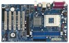
... JUSB45) (see p.7 item 24) GND +5VA BACKOUT-R BACKOUT-L 1 A U D - O U T- R MIC-POWER MIC This is shared with the USB 2.0 ports 4,5 on ASRock I/O PlusTM will not be able to function. Internal Audio Connectors (4-pin CD1, 4-pin AUX1) (CD1: see p.7 item 20) (AUX1: see p.7 item 18) USB_PWR P-7 P+7 GND...ports on the drive. L DUMMY A U D - Then connect the white end of SATA power cable to the power connector of the power supply. O U T- Serial ATA (SATA) Power Cable (Optional) connect to the SATA HDD power connector connect to the power supply Please connect the black end of...
... JUSB45) (see p.7 item 24) GND +5VA BACKOUT-R BACKOUT-L 1 A U D - O U T- R MIC-POWER MIC This is shared with the USB 2.0 ports 4,5 on ASRock I/O PlusTM will not be able to function. Internal Audio Connectors (4-pin CD1, 4-pin AUX1) (CD1: see p.7 item 20) (AUX1: see p.7 item 18) USB_PWR P-7 P+7 GND...ports on the drive. L DUMMY A U D - Then connect the white end of SATA power cable to the power connector of the power supply. O U T- Serial ATA (SATA) Power Cable (Optional) connect to the SATA HDD power connector connect to the power supply Please connect the black end of...

User Manual
Page 18
...action to insert and remove the SATA HDDs while the system is still power-on and in working condition. STEP 4: Connect the other end of the SATA data cable to the SATA hard disk. 2.8 Hot Plug and Hot Swap Functions for SATA HDDs K7VT6 motherboard supports Hot Plug and Hot ...Swap functions for internal storage devices. 2.7 Serial ATA (SATA) Hard Disks Installation This motherboard adopts VIA VT8237 southbridge...
...action to insert and remove the SATA HDDs while the system is still power-on and in working condition. STEP 4: Connect the other end of the SATA data cable to the SATA hard disk. 2.8 Hot Plug and Hot Swap Functions for SATA HDDs K7VT6 motherboard supports Hot Plug and Hot ...Swap functions for internal storage devices. 2.7 Serial ATA (SATA) Hard Disks Installation This motherboard adopts VIA VT8237 southbridge...

User Manual
Page 19
... in it! Formatting the floppy diskette will start the OS installation. Before you start to configure the RAID function, you need to make an SATA driver diskette before you install the OS. STEP 5: The system will lose ALL data in the Support CD for boot devices selection appears. STEP... 1: Insert the ASRock Support CD into your optical drive to boot your system, or you may also set RAID 0 / RAID 1 / JBOD configuration before you start to...
... in it! Formatting the floppy diskette will start the OS installation. Before you start to configure the RAID function, you need to make an SATA driver diskette before you install the OS. STEP 5: The system will lose ALL data in the Support CD for boot devices selection appears. STEP... 1: Insert the ASRock Support CD into your optical drive to boot your system, or you may also set RAID 0 / RAID 1 / JBOD configuration before you start to...
User Manual
Page 32
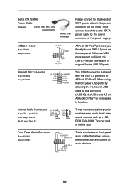
... routine by skipping memory retestings. 4. VERSION 3.31a Security Power Boot Exit Quick Boot Mode Boot Up Num-Lock Boot To OS/2 Boot From Network VIA SATA Raid Utility Enabled On No Disabled Enabled [ Setup Help ] to set the boot device priority. 32 VIA...
... routine by skipping memory retestings. 4. VERSION 3.31a Security Power Boot Exit Quick Boot Mode Boot Up Num-Lock Boot To OS/2 Boot From Network VIA SATA Raid Utility Enabled On No Disabled Enabled [ Setup Help ] to set the boot device priority. 32 VIA...
