
User Manual
Page 3
... Menu 30 3. Software Support 24 4.1 Install Operating System 24 4.2 Support CD Information 24 4.2.1 Running Support CD 24 4.2.2 Drivers Menu 24 4.2.3 Utilities Menu 24 4.2.4 ASRock "PC-DIY Live Demo" Program 24 4.2.5 Contact Information 24 Appendix 25 1. Power Setup Menu 31 4. Exit Menu 33 3 Boot Setup Menu 32 5. Installation 9... 18 2.8 Hot Plug and Hot Swap Functions for SATA HDDs 18 2.9 Making An SATA Driver Diskette 19 3. Introduction 4 1.1 Package Contents 4 1.2 Specifications 5 1.3 Motherboard Layout 7 1.4 ASRock I/O Plus 8 TM ...2. Contents 1.
... Menu 30 3. Software Support 24 4.1 Install Operating System 24 4.2 Support CD Information 24 4.2.1 Running Support CD 24 4.2.2 Drivers Menu 24 4.2.3 Utilities Menu 24 4.2.4 ASRock "PC-DIY Live Demo" Program 24 4.2.5 Contact Information 24 Appendix 25 1. Power Setup Menu 31 4. Exit Menu 33 3 Boot Setup Menu 32 5. Installation 9... 18 2.8 Hot Plug and Hot Swap Functions for SATA HDDs 18 2.9 Making An SATA Driver Diskette 19 3. Introduction 4 1.1 Package Contents 4 1.2 Specifications 5 1.3 Motherboard Layout 7 1.4 ASRock I/O Plus 8 TM ...2. Contents 1.

User Manual
Page 4
... the latest memory and CPU support lists on page 25 for purchasing ASRock K7VT6 motherboard, a reliable motherboard produced under ASRock's consistently stringent quality control. ASRock website http://www.asrock.com 1.1 Package Contents 1 x ASRock K7VT6 Motherboard (ATX Form Factor: 12.0-in x 7.0-in, 30.5 cm x 17.8 cm) 1 x ASRock K7VT6 Quick Installation Guide 1 x ASRock K7VT6 Support CD 1 x Ultra ATA 66/100/133 IDE Ribbon Cable (80-conductor...
... the latest memory and CPU support lists on page 25 for purchasing ASRock K7VT6 motherboard, a reliable motherboard produced under ASRock's consistently stringent quality control. ASRock website http://www.asrock.com 1.1 Package Contents 1 x ASRock K7VT6 Motherboard (ATX Form Factor: 12.0-in x 7.0-in, 30.5 cm x 17.8 cm) 1 x ASRock K7VT6 Quick Installation Guide 1 x ASRock K7VT6 Support CD 1 x Ultra ATA 66/100/133 IDE Ribbon Cable (80-conductor...

User Manual
Page 5
... Audio LAN: Speed: 802.3u (10/100 Ethernet), Supports Wake-On-LAN Hardware Monitor: CPU Temperature Sensing Motherboard Temperature Sensing CPU Overheat Shutdown to Protect CPU Life (ASRock U-COP)(see CAUTION 1) CPU Fan Tachometer Chassis Fan Tachometer Voltage Monitoring: +12V, +5V, +3.3V, Vcore... USB 2.0 ports: include 6 ready-to-use USB 2.0 ports on the rear panel, plus one on-board header supporting 2 extra USB 2.0 ports (see CAUTION 3) ASRock I/O PlusTM: 1 PS/2 Mouse Port, 1 PS/2 Keyboard Port, 1 Serial Port: COM1, 1 Parallel Port (ECP/EPP Support) 6 ready-to-use USB 2.0 ...
... Audio LAN: Speed: 802.3u (10/100 Ethernet), Supports Wake-On-LAN Hardware Monitor: CPU Temperature Sensing Motherboard Temperature Sensing CPU Overheat Shutdown to Protect CPU Life (ASRock U-COP)(see CAUTION 1) CPU Fan Tachometer Chassis Fan Tachometer Voltage Monitoring: +12V, +5V, +3.3V, Vcore... USB 2.0 ports: include 6 ready-to-use USB 2.0 ports on the rear panel, plus one on-board header supporting 2 extra USB 2.0 ports (see CAUTION 3) ASRock I/O PlusTM: 1 PS/2 Mouse Port, 1 PS/2 Keyboard Port, 1 Serial Port: COM1, 1 Parallel Port (ECP/EPP Support) 6 ready-to-use USB 2.0 ...

User Manual
Page 6
... to Microsoft® official document at http://www.microsoft.com/whdc/hwdev/bus/USB/USB2support.mspx 4. The CPU host frequency of this motherboard! It may cause the instability of "User Manual" in BIOS. Please refer to perform over clocking. While CPU overheat is determined by... jumper-setting. Before you install the PC system. 2. Although this motherboard is detected, the system will automatically shutdown. See page 13 for the details of "FSB Select Jumpers" adjustment, and page 25 of ...
... to Microsoft® official document at http://www.microsoft.com/whdc/hwdev/bus/USB/USB2support.mspx 4. The CPU host frequency of this motherboard! It may cause the instability of "User Manual" in BIOS. Please refer to perform over clocking. While CPU overheat is determined by... jumper-setting. Before you install the PC system. 2. Although this motherboard is detected, the system will automatically shutdown. See page 13 for the details of "FSB Select Jumpers" adjustment, and page 25 of ...

User Manual
Page 7
1.3 Motherboard Layout 1 2 34 5 6 17.8cm (7.0 in) PS/2 MOUSE PS/2 KEYBOARD PS2_USB_PWR1 1 FID4 FID3 FID2 FID1 FID0 J1 CPU_FAN1 1 1 1 1 1 SOCKET 462 SERIAL PORT (COM1) PARALLEL PORT DDR 1 (... Top: RJ-45 B: USB1 USB 2.0 T: USB4 1 B: USB5 JUSB45 VIA KT600 CHIPSET Top: Line In Center: Line Out Bottom: Mic In 27 2MB BIOS AGP 8X K7VT6 LAN PHY SUPER I/O 1.5V_AGP1 IDE1 IDE2 7 8 9 26 25 24 23 22 GAME1 1 DDR400 PCI1 PCI2 1 FSB_SEL0 1 FSB_SEL1 1 FSB_SEL2 1 AUDIO1 JR1 JL1 CMOS BATTERY USB2.0 1 CLRCMOS2...
1.3 Motherboard Layout 1 2 34 5 6 17.8cm (7.0 in) PS/2 MOUSE PS/2 KEYBOARD PS2_USB_PWR1 1 FID4 FID3 FID2 FID1 FID0 J1 CPU_FAN1 1 1 1 1 1 SOCKET 462 SERIAL PORT (COM1) PARALLEL PORT DDR 1 (... Top: RJ-45 B: USB1 USB 2.0 T: USB4 1 B: USB5 JUSB45 VIA KT600 CHIPSET Top: Line In Center: Line Out Bottom: Mic In 27 2MB BIOS AGP 8X K7VT6 LAN PHY SUPER I/O 1.5V_AGP1 IDE1 IDE2 7 8 9 26 25 24 23 22 GAME1 1 DDR400 PCI1 PCI2 1 FSB_SEL0 1 FSB_SEL1 1 FSB_SEL2 1 AUDIO1 JR1 JL1 CMOS BATTERY USB2.0 1 CLRCMOS2...
User Manual
Page 9
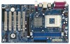
...an ATX form factor (12.0-in x 7.0-in the bag that the motherboard fits into the screw holes to secure the motherboard to the motherboard, peripherals, and/or components. 1. To avoid damaging the motherboard components due to static electricity, NEVER place your chassis to ensure that ... from the power supply. Hold components by the edges and do so may damage the motherboard. 9 Whenever you install or remove any motherboard settings. Before you uninstall any component. 2. 2. Installation K7VT6 is detached from the wall socket before you handle components. 3. Failure to use a ...
...an ATX form factor (12.0-in x 7.0-in the bag that the motherboard fits into the screw holes to secure the motherboard to the motherboard, peripherals, and/or components. 1. To avoid damaging the motherboard components due to static electricity, NEVER place your chassis to ensure that ... from the power supply. Hold components by the edges and do so may damage the motherboard. 9 Whenever you install or remove any motherboard settings. Before you uninstall any component. 2. 2. Installation K7VT6 is detached from the wall socket before you handle components. 3. Failure to use a ...

User Manual
Page 11
Step 2. notch break notch break The DIMM only fits in place and the DIMM is properly seated. 11 2.3 Installation of Memory Modules (DIMM) K7VT6 motherboard provides two 184-pin DDR (Double Data Rate) DIMM slots. Step 3. Unlock a DIMM slot by pressing the retaining clips outward. Step 1. Align a ... slot. Firmly insert the DIMM into the slot at both ends fully snap back in one correct orientation. Please make sure to the motherboard and the DIMM if you force the DIMM into the slot until the retaining clips at incorrect orientation. It will cause permanent damage to...
Step 2. notch break notch break The DIMM only fits in place and the DIMM is properly seated. 11 2.3 Installation of Memory Modules (DIMM) K7VT6 motherboard provides two 184-pin DDR (Double Data Rate) DIMM slots. Step 3. Unlock a DIMM slot by pressing the retaining clips outward. Step 1. Align a ... slot. Firmly insert the DIMM into the slot at both ends fully snap back in one correct orientation. Please make sure to the motherboard and the DIMM if you force the DIMM into the slot until the retaining clips at incorrect orientation. It will cause permanent damage to...

User Manual
Page 12
...graphics card. Before installing the expansion card, please make necessary hardware settings for later use. Please read the documentation of your motherboard is used to install expansion cards that you start the installation. Remove the system unit cover (if your graphics card, ...before you intend to use a 3.3V AGP card on K7VT6 motherboard. Please do NOT use . 2.4 Expansion Slots (PCI and AGP Slots) There are used to install a graphics card. The ASRock AGP slot has a special design of this motherboard! AGP slot: The AGP slot is already installed in ...
...graphics card. Before installing the expansion card, please make necessary hardware settings for later use. Please read the documentation of your motherboard is used to install expansion cards that you start the installation. Remove the system unit cover (if your graphics card, ...before you intend to use a 3.3V AGP card on K7VT6 motherboard. Please do NOT use . 2.4 Expansion Slots (PCI and AGP Slots) There are used to install a graphics card. The ASRock AGP slot has a special design of this motherboard! AGP slot: The AGP slot is already installed in ...

User Manual
Page 13
..., time, and system setup parameters. To clear and reset the system parameters to set the CPU FSB frequency. If you to the FSB of this motherboard is "Open". You must boot up events. Clear CMOS Jumper (CLRCMOS2) (see p.7 item 22) 2-pin jumper Note: CLRCMOS2 allows you need to enable (see p.7 item...
..., time, and system setup parameters. To clear and reset the system parameters to set the CPU FSB frequency. If you to the FSB of this motherboard is "Open". You must boot up events. Clear CMOS Jumper (CLRCMOS2) (see p.7 item 22) 2-pin jumper Note: CLRCMOS2 allows you need to enable (see p.7 item...

User Manual
Page 15
... disk drive to the primary IDE connector (IDE1, blue) and CD-ROM to the SATA hard disk or the SATA connector on this motherboard, please set the IDE device as "Master". Besides, to optimize compatibility and performance, please connect your IDE device vendor for internal storage devices... Secondary IDE Connector (Black) (39-pin IDE2, see p.7 item 7) PIN1 IDE1 PIN1 IDE2 connect the blue end connect the black end to the motherboard to the instruction of the SATA data cable can be connected to the secondary IDE connector (IDE2, black). Please refer to the IDE devices 80...
... disk drive to the primary IDE connector (IDE1, blue) and CD-ROM to the SATA hard disk or the SATA connector on this motherboard, please set the IDE device as "Master". Besides, to optimize compatibility and performance, please connect your IDE device vendor for internal storage devices... Secondary IDE Connector (Black) (39-pin IDE2, see p.7 item 7) PIN1 IDE1 PIN1 IDE2 connect the blue end connect the black end to the motherboard to the instruction of the SATA data cable can be connected to the secondary IDE connector (IDE2, black). Please refer to the IDE devices 80...

User Manual
Page 18
... RAID1 then it is called "Hot Plug" for the action to the SATA hard disk. 2.8 Hot Plug and Hot Swap Functions for SATA HDDs K7VT6 motherboard supports Hot Plug and Hot Swap functions for internal storage devices. STEP 1: Install the SATA hard disks into the SATA HDD. 2.7 Serial ATA (...SATA) Hard Disks Installation This motherboard adopts VIA VT8237 southbridge chipset that it cannot perform Hot Plug if the OS has been installed into the drive bays of your chassis. This...
... RAID1 then it is called "Hot Plug" for the action to the SATA hard disk. 2.8 Hot Plug and Hot Swap Functions for SATA HDDs K7VT6 motherboard supports Hot Plug and Hot Swap functions for internal storage devices. STEP 1: Install the SATA hard disks into the SATA HDD. 2.7 Serial ATA (...SATA) Hard Disks Installation This motherboard adopts VIA VT8237 southbridge chipset that it cannot perform Hot Plug if the OS has been installed into the drive bays of your chassis. This...
User Manual
Page 20
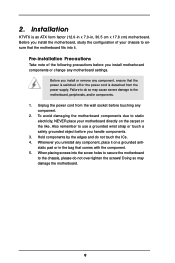
...-driven program, which allows you wish to scroll through its test routines. You may also restart the system by pressing the reset button on the motherboard stores the BIOS Setup Utility. Because the BIOS software is designed to enter the BIOS Setup Utility, otherwise, POST will continue with its various sub...
...-driven program, which allows you wish to scroll through its test routines. You may also restart the system by pressing the reset button on the motherboard stores the BIOS Setup Utility. Because the BIOS software is designed to enter the BIOS Setup Utility, otherwise, POST will continue with its various sub...

User Manual
Page 24
...if "AUTORUN" is enabled in your own PC system step by step. or you need to contact ASRock or want to install your computer. Software Support 4.1 Install Operating System This motherboard supports various Microsoft® Windows® operating systems: 98 SE / ME / 2000 / XP. ... devices drivers if the system detects installed devices. You may contact your OS documentation for more about ASRock, welcome to your dealer for general reference only. Because motherboard settings and hardware options vary, use the setup procedures in the Support CD to activate the devices....
...if "AUTORUN" is enabled in your own PC system step by step. or you need to contact ASRock or want to install your computer. Software Support 4.1 Install Operating System This motherboard supports various Microsoft® Windows® operating systems: 98 SE / ME / 2000 / XP. ... devices drivers if the system detects installed devices. You may contact your OS documentation for more about ASRock, welcome to your dealer for general reference only. Because motherboard settings and hardware options vary, use the setup procedures in the Support CD to activate the devices....

User Manual
Page 25
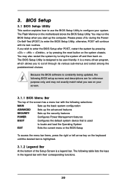
... This allows user to set the FSB jumper adjustment according to select this option, which will let the CPU host frequency of this motherboard determined by the jumper-setting, you must set CPU host frequency manually. It will allow better tolerance for better system stability. CPU ...Host Frequency [Auto] It is recommended to your AMD CPU before you use this motherboard is [Disabled]. You may cause problems during operation. VERSION 3.31a Security Power Boot Exit Spread Spectrum CPU Host Frequency Actual Frequency DRAM...
... This allows user to set the FSB jumper adjustment according to select this option, which will let the CPU host frequency of this motherboard determined by the jumper-setting, you must set CPU host frequency manually. It will allow better tolerance for better system stability. CPU ...Host Frequency [Auto] It is recommended to your AMD CPU before you use this motherboard is [Disabled]. You may cause problems during operation. VERSION 3.31a Security Power Boot Exit Spread Spectrum CPU Host Frequency Actual Frequency DRAM...

User Manual
Page 29
... Hardware Monitor You may check the status of the hardware on your system. OnBoard AC'97 Audio Select [Disabled], [Auto] or [Enabled] for CPU temperature, Motherboard temperature, CPU fan speed, and critical voltage. Advanced AMIBIOS SETUP UTILITY - It allows you to monitor the parameters for the onboard AC'97 Audio feature...
... Hardware Monitor You may check the status of the hardware on your system. OnBoard AC'97 Audio Select [Disabled], [Auto] or [Enabled] for CPU temperature, Motherboard temperature, CPU fan speed, and critical voltage. Advanced AMIBIOS SETUP UTILITY - It allows you to monitor the parameters for the onboard AC'97 Audio feature...

