
User Manual
Page 3
... BIOS Setup Menu 25 2. Introduction 4 1.1 Package Contents 4 1.2 Specifications 5 1.3 Motherboard Layout 7 1.4 ASRock I/O Plus 8 TM ...2. Power Setup Menu 31 4. Exit Menu 33 3 Contents 1. Boot Setup Menu 32 5. Installation 9 Pre-installation Precautions 9 2.1 CPU Installation 10 2.2 Installation of CPU Fan and Heatsink 10 2.3 Installation of Memory Modules (DIMM 11 2.4 Expansion Slots (PCI and AGP Slots 12 2.5 Jumpers Setup 13 2.6 Onboard Headers and Connectors 15 2.7 Serial ATA (SATA) Hard Disks Installation 18 2.8 Hot Plug and Hot Swap Functions for SATA HDDs...
... BIOS Setup Menu 25 2. Introduction 4 1.1 Package Contents 4 1.2 Specifications 5 1.3 Motherboard Layout 7 1.4 ASRock I/O Plus 8 TM ...2. Power Setup Menu 31 4. Exit Menu 33 3 Contents 1. Boot Setup Menu 32 5. Installation 9 Pre-installation Precautions 9 2.1 CPU Installation 10 2.2 Installation of CPU Fan and Heatsink 10 2.3 Installation of Memory Modules (DIMM 11 2.4 Expansion Slots (PCI and AGP Slots 12 2.5 Jumpers Setup 13 2.6 Onboard Headers and Connectors 15 2.7 Serial ATA (SATA) Hard Disks Installation 18 2.8 Hot Plug and Hot Swap Functions for SATA HDDs...

User Manual
Page 4
... found in Floppy Drive Ribbon Cable 1 x Serial ATA (SATA) Data Cable 1 x Serial ATA (SATA) HDD Power Cable (Optional) 1 x ASRock I/O PlusTM Shield 4 It delivers excellent performance with robust design conforming to ASRock's commitment to change without further notice. Chapter 1 and 2 of this manual occur, the updated version will be subject to quality and endurance. Chapter 3 and 4 contain basic BIOS setup and support CD information. You may find the latest memory and CPU support lists on ASRock website...
... found in Floppy Drive Ribbon Cable 1 x Serial ATA (SATA) Data Cable 1 x Serial ATA (SATA) HDD Power Cable (Optional) 1 x ASRock I/O PlusTM Shield 4 It delivers excellent performance with robust design conforming to ASRock's commitment to change without further notice. Chapter 1 and 2 of this manual occur, the updated version will be subject to quality and endurance. Chapter 3 and 4 contain basic BIOS setup and support CD information. You may find the latest memory and CPU support lists on ASRock website...

User Manual
Page 5
... Supports up to 2 Floppy Disk Drives Audio: 5.1 Channels AC'97 Audio LAN: Speed: 802.3u (10/100 Ethernet), Supports Wake-On-LAN Hardware Monitor: CPU Temperature Sensing Motherboard Temperature Sensing CPU Overheat Shutdown to Protect CPU Life (ASRock U-COP)(see CAUTION 1) CPU Fan Tachometer Chassis Fan Tachometer Voltage Monitoring: +12V, +5V, +3.3V, Vcore PCI slots: 5 Slots with PCI Specification 2.2 AGP slot: 1 AGP Slot, Supports 1.5V, 8X/4X AGP Card (see CAUTION 2) USB 2.0: 8 USB 2.0 ports: include 6 ready-to-use USB 2.0 ports on the rear panel, plus one on-board header...
... Supports up to 2 Floppy Disk Drives Audio: 5.1 Channels AC'97 Audio LAN: Speed: 802.3u (10/100 Ethernet), Supports Wake-On-LAN Hardware Monitor: CPU Temperature Sensing Motherboard Temperature Sensing CPU Overheat Shutdown to Protect CPU Life (ASRock U-COP)(see CAUTION 1) CPU Fan Tachometer Chassis Fan Tachometer Voltage Monitoring: +12V, +5V, +3.3V, Vcore PCI slots: 5 Slots with PCI Specification 2.2 AGP slot: 1 AGP Slot, Supports 1.5V, 8X/4X AGP Card (see CAUTION 2) USB 2.0: 8 USB 2.0 ports: include 6 ready-to-use USB 2.0 ports on the rear panel, plus one on-board header...

User Manual
Page 6
... "FSB Select Jumpers" according to Microsoft® official document at http://www.microsoft.com/whdc/hwdev/bus/USB/USB2support.mspx 4. Power Management for advanced users' reference, see CAUTION 4) Microsoft® Windows® 98 SE / ME / 2000 / XP Compliant CAUTION! 1. BIOS: OS: AMI legal BIOS, Supports "Plug and Play", ACPI 1.1 Compliance Wake-Up Events, SMBIOS 2.3.1 Support, CPU Frequency Stepless Control (only for USB 2.0 works fine under Microsoft® Windows®...
... "FSB Select Jumpers" according to Microsoft® official document at http://www.microsoft.com/whdc/hwdev/bus/USB/USB2support.mspx 4. Power Management for advanced users' reference, see CAUTION 4) Microsoft® Windows® 98 SE / ME / 2000 / XP Compliant CAUTION! 1. BIOS: OS: AMI legal BIOS, Supports "Plug and Play", ACPI 1.1 Compliance Wake-Up Events, SMBIOS 2.3.1 Support, CPU Frequency Stepless Control (only for USB 2.0 works fine under Microsoft® Windows®...

User Manual
Page 7
... 11 South Bridge Controller 12 Primary Serial ATA Connector (SATA1) 13 Secondary Serial ATA Connector (SATA2) 14 Power LED Connector (PWR_LED1) 15 Chassis Fan Connector (CHA_FAN1) 16 System Panel Connector (PANEL1) 17 Chassis Speaker Connector (SPEAKER 1) 18 USB 2.0 Connector (USB67, Blue) 19 Floppy Connector (FLOPPY1) 20 Internal Audio Connector: CD1 (Black) 21 Internal Audio Connector: AUX1 (White) 22 Clear CMOS Jumper (CLRCMOS2) 23 JR1 / JL1 Jumpers 24 Front Panel Audio Connector (AUDIO1) 25 PCI Slots (PCI1- 5) 26 Game Port Connector (GAME1) 27 Flash Memory 28 Shared USB 2.0 Header (JUSB45...
... 11 South Bridge Controller 12 Primary Serial ATA Connector (SATA1) 13 Secondary Serial ATA Connector (SATA2) 14 Power LED Connector (PWR_LED1) 15 Chassis Fan Connector (CHA_FAN1) 16 System Panel Connector (PANEL1) 17 Chassis Speaker Connector (SPEAKER 1) 18 USB 2.0 Connector (USB67, Blue) 19 Floppy Connector (FLOPPY1) 20 Internal Audio Connector: CD1 (Black) 21 Internal Audio Connector: AUX1 (White) 22 Clear CMOS Jumper (CLRCMOS2) 23 JR1 / JL1 Jumpers 24 Front Panel Audio Connector (AUDIO1) 25 PCI Slots (PCI1- 5) 26 Game Port Connector (GAME1) 27 Flash Memory 28 Shared USB 2.0 Header (JUSB45...

User Manual
Page 12
... completely seated on the slot. 2.4 Expansion Slots (PCI and AGP Slots) There are used to install a graphics card. Please do NOT use . Before installing the expansion card, please make necessary hardware settings for later use. Step 6. Fasten the card to the chassis with screws. PCI slots: PCI slots are 5 PCI slots and 1 AGP slot on the AGP slot of your motherboard is used to install expansion cards that the power supply is switched off or the power cord is unplugged. Step...
... completely seated on the slot. 2.4 Expansion Slots (PCI and AGP Slots) There are used to install a graphics card. Please do NOT use . Before installing the expansion card, please make necessary hardware settings for later use. Step 6. Fasten the card to the chassis with screws. PCI slots: PCI slots are 5 PCI slots and 1 AGP slot on the AGP slot of your motherboard is used to install expansion cards that the power supply is switched off or the power cord is unplugged. Step...

User Manual
Page 15
.../133 cable Note: If you use only one IDE device on the motherboard. 15 FDD Connector (33-pin FLOPPY1) (see p.7 item 13) SATA1 SATA2 These two Serial ATA (SATA) connectors support SATA data cables for the details. 2.6 Connectors Connectors are NOT jumpers. Serial ATA Connectors (SATA1: see p.7 item 12) (SATA2: see p.7 item 19) Pin1 FLOPPY1 the red-striped side to the SATA hard disk or the SATA connector on this motherboard, please set the IDE device as...
.../133 cable Note: If you use only one IDE device on the motherboard. 15 FDD Connector (33-pin FLOPPY1) (see p.7 item 13) SATA1 SATA2 These two Serial ATA (SATA) connectors support SATA data cables for the details. 2.6 Connectors Connectors are NOT jumpers. Serial ATA Connectors (SATA1: see p.7 item 12) (SATA2: see p.7 item 19) Pin1 FLOPPY1 the red-striped side to the SATA hard disk or the SATA connector on this motherboard, please set the IDE device as...
User Manual
Page 16
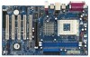
...front panel audio cable that allows convenient connection and control of audio devices. 16 Shared USB 2.0 Header (9-pin JUSB45) (see p.7 item 24) GND +5VA BACKOUT-R BACKOUT-L 1 A U D - Serial ATA (SATA) Power Cable (Optional) connect to the SATA HDD power connector connect to the power supply Please connect the black end of SATA power cable to support 2 extra USB 2.0 ports. Then connect the white end of SATA power cable to function. When using the front panel USB ports by attaching the front panel USB cable to this USB 2.0 header is available to the power connector on ASRock...
...front panel audio cable that allows convenient connection and control of audio devices. 16 Shared USB 2.0 Header (9-pin JUSB45) (see p.7 item 24) GND +5VA BACKOUT-R BACKOUT-L 1 A U D - Serial ATA (SATA) Power Cable (Optional) connect to the SATA HDD power connector connect to the power supply Please connect the black end of SATA power cable to support 2 extra USB 2.0 ports. Then connect the white end of SATA power cable to function. When using the front panel USB ports by attaching the front panel USB cable to this USB 2.0 header is available to the power connector on ASRock...
User Manual
Page 17
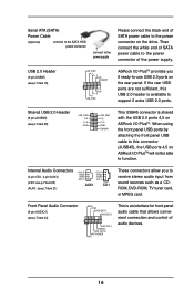
... MIDI_IN Connect a Game cable to this connector. Power LED Connector (3-pin PWR_LED1) (see p.7 item 14) Game Connector (15-pin GAME1) (see p.7 item 2) CPU_FAN_SPEED +12V GND Please connect a CPU fan cable to this connector. Please connect the chassis speaker to the ground pin. System Panel Connector (9-pin PANEL1) (see p.7 item 16) Chassis Speaker Connector (4-pin SPEAKER 1) (see p.7 item 15) GND +12V CHA_FAN_SPEED Please connect a chassis fan cable to this connector and match the black wire to this connector if the Game port bracket is installed. 1 +5V...
... MIDI_IN Connect a Game cable to this connector. Power LED Connector (3-pin PWR_LED1) (see p.7 item 14) Game Connector (15-pin GAME1) (see p.7 item 2) CPU_FAN_SPEED +12V GND Please connect a CPU fan cable to this connector. Please connect the chassis speaker to the ground pin. System Panel Connector (9-pin PANEL1) (see p.7 item 16) Chassis Speaker Connector (4-pin SPEAKER 1) (see p.7 item 15) GND +12V CHA_FAN_SPEED Please connect a chassis fan cable to this connector and match the black wire to this connector if the Game port bracket is installed. 1 +5V...

User Manual
Page 19
... floppy drive at this moment!) STEP 2: During POST at the beginning of system boot-up, press key, and then a window for proper configuration. STEP 3: When you see these messages, Please insert a diskette into the floppy diskette. Formatting the floppy diskette will need to check the installation guide in the Support CD for boot devices selection appears. Start to format and copy files [YN]? STEP 1: Insert the ASRock Support...
... floppy drive at this moment!) STEP 2: During POST at the beginning of system boot-up, press key, and then a window for proper configuration. STEP 3: When you see these messages, Please insert a diskette into the floppy diskette. Formatting the floppy diskette will need to check the installation guide in the Support CD for boot devices selection appears. Start to format and copy files [YN]? STEP 1: Insert the ASRock Support...
User Manual
Page 20
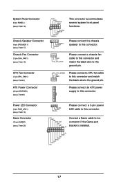
... reset button on your system. Because the BIOS software is a menu-driven program, which allows you see on the system chassis. BIOS Setup 3.1 BIOS Setup Utility This section explains how to use the BIOS Setup Utility to enter the BIOS Setup after POST, restart the system by pressing + + , or by turning the system off and then back on the motherboard stores the BIOS Setup Utility. If you start up the security features POWER Configures Power Management features BOOT Configures the default...
... reset button on your system. Because the BIOS software is a menu-driven program, which allows you see on the system chassis. BIOS Setup 3.1 BIOS Setup Utility This section explains how to use the BIOS Setup Utility to enter the BIOS Setup after POST, restart the system by pressing + + , or by turning the system off and then back on the motherboard stores the BIOS Setup Utility. If you start up the security features POWER Configures Power Management features BOOT Configures the default...
User Manual
Page 21
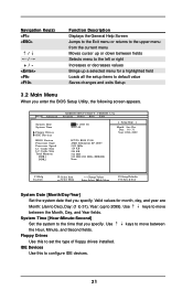
... Time Floppy Drives IDE Devices BIOS Version Processor Type Processor Speed L1 Cache Size L2 Cache Size Total Memory DDR1 DDR2 AMIBIOS SETUP UTILITY - Use keys to move between the Month, Day, and Year fields. Valid values for month, day, and year are Month: (Jan to Dec), Day: (1 to 31), Year: (up a selected menu for a highlighted field Loads all the setup items to the time that you enter the BIOS Setup Utility, the following screen...
... Time Floppy Drives IDE Devices BIOS Version Processor Type Processor Speed L1 Cache Size L2 Cache Size Total Memory DDR1 DDR2 AMIBIOS SETUP UTILITY - Use keys to move between the Month, Day, and Year fields. Valid values for month, day, and year are Month: (Jan to Dec), Day: (1 to 31), Year: (up a selected menu for a highlighted field Loads all the setup items to the time that you enter the BIOS Setup Utility, the following screen...
User Manual
Page 23
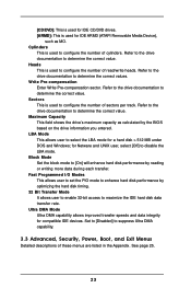
... hard disk performance by optimizing the hard disk timing. 32 Bit Transfer Mode It allows user to enable 32-bit access to suppress Ultra DMA capability. 3.3 Advanced, Security, Power, Boot, and Exit Menus Detailed descriptions of cylinders. Heads This is used to configure the number of these menus are listed in the Appendix. [CD/DVD]: This is used for IDE CD/DVD drives. [ARMD]: This is used for IDE ARMD (ATAPI Removable Media Device...
... hard disk performance by optimizing the hard disk timing. 32 Bit Transfer Mode It allows user to enable 32-bit access to suppress Ultra DMA capability. 3.3 Advanced, Security, Power, Boot, and Exit Menus Detailed descriptions of cylinders. Heads This is used to configure the number of these menus are listed in the Appendix. [CD/DVD]: This is used for IDE CD/DVD drives. [ARMD]: This is used for IDE ARMD (ATAPI Removable Media Device...

User Manual
Page 24
... with the motherboard contains necessary drivers and useful utilities that the motherboard supports. Because motherboard settings and hardware options vary, use the setup procedures in your OS documentation for more about ASRock, welcome to display the menus. 4.2.2 Drivers Menu The Drivers Menu shows the available devices drivers if the system detects installed devices. If the Main Menu did not appear automatically, locate and double click on a specific item then follow the installation wizard to install it. 4.2.4 ASRock PC...
... with the motherboard contains necessary drivers and useful utilities that the motherboard supports. Because motherboard settings and hardware options vary, use the setup procedures in your OS documentation for more about ASRock, welcome to display the menus. 4.2.2 Drivers Menu The Drivers Menu shows the available devices drivers if the system detects installed devices. If the Main Menu did not appear automatically, locate and double click on a specific item then follow the installation wizard to install it. 4.2.4 ASRock PC...

User Manual
Page 25
... BIOS Setup Menu Main Advanced AMIBIOS SETUP UTILITY - Chipset Configuration Resource Configuration Peripheral Configuration System Hardware Monitor F1:Help Esc:Exit :Select Item :Select Menu +/-:Change Values Enter:Select Sub-Menu F9:Setup Defaults F10:Save & Exit Spread Spectrum This field should always be [Disabled] for memory compatibility when it is not recommended unless you the following BIOS Setup menus: "Advanced," "Security," "Power," "Boot," and "Exit." 1. DRAM Frequency If set the FSB jumper adjustment according to your AMD CPU before...
... BIOS Setup Menu Main Advanced AMIBIOS SETUP UTILITY - Chipset Configuration Resource Configuration Peripheral Configuration System Hardware Monitor F1:Help Esc:Exit :Select Item :Select Menu +/-:Change Values Enter:Select Sub-Menu F9:Setup Defaults F10:Save & Exit Spread Spectrum This field should always be [Disabled] for memory compatibility when it is not recommended unless you the following BIOS Setup menus: "Advanced," "Security," "Power," "Boot," and "Exit." 1. DRAM Frequency If set the FSB jumper adjustment according to your AMD CPU before...

User Manual
Page 26
... graphics memory. Disable this to enable or disable the support to speed up the V-Link speed. It is used to a section of USB controller. Chipset Configuration Advanced AMIBIOS SETUP UTILITY - The default value is recommended to select [4X], [2X], [1X] as mouse, keyboard,... USB Controller Use this to leave this field as default. It is [Normal]. 26 etc. Configuration options: [Auto], [2T], [2.5T], [3T]. VERSION 3.31a Chipset Configuration [ Setup Help ] AGP Mode AGP Aperture Size AGP Fast Write PCI Delay Transaction USB Controller USB Device Legacy Support...
... graphics memory. Disable this to enable or disable the support to speed up the V-Link speed. It is used to a section of USB controller. Chipset Configuration Advanced AMIBIOS SETUP UTILITY - The default value is recommended to select [4X], [2X], [1X] as mouse, keyboard,... USB Controller Use this to leave this field as default. It is [Normal]. 26 etc. Configuration options: [Auto], [2T], [2.5T], [3T]. VERSION 3.31a Chipset Configuration [ Setup Help ] AGP Mode AGP Aperture Size AGP Fast Write PCI Delay Transaction USB Controller USB Device Legacy Support...
User Manual
Page 28
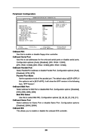
... UTILITY - If this to enable or disable the floppy drive controller. OnBoard Game Port Select address for Midi Port or disable Midi Port. VERSION 3.31a Peripheral Configuration [ Setup Help ] OnBoard FDC OnBoard Serial Port OnBoard Parallel Port Parallel Port Mode EPP Version Parallel Port IRQ Parallel Port DMA Channel OnBoard Midi Port Midi IRQ Select OnBoard Game Port OnBoard IDE OnBoard LAN OnBoard AC' 97 Audio Auto Auto Auto ECP+EPP 1.9 Auto Auto Disabled 5 200h Enabled Enabled Auto to set to enable or disable the onboard IDE controller. 28 Configuration options: [Auto...
... UTILITY - If this to enable or disable the floppy drive controller. OnBoard Game Port Select address for Midi Port or disable Midi Port. VERSION 3.31a Peripheral Configuration [ Setup Help ] OnBoard FDC OnBoard Serial Port OnBoard Parallel Port Parallel Port Mode EPP Version Parallel Port IRQ Parallel Port DMA Channel OnBoard Midi Port Midi IRQ Select OnBoard Game Port OnBoard IDE OnBoard LAN OnBoard AC' 97 Audio Auto Auto Auto ECP+EPP 1.9 Auto Auto Disabled 5 200h Enabled Enabled Auto to set to enable or disable the onboard IDE controller. 28 Configuration options: [Auto...

User Manual
Page 29
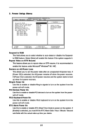
... AMIBIOS SETUP UTILITY - OnBoard AC'97 Audio Select [Disabled], [Auto] or [Enabled] for CPU temperature, Motherboard temperature, CPU fan speed, and critical voltage. VERSION 3.31a System Hardware Monitor [ Setup Help ] CPU Temperature M / B Temperature CPU FAN Speed Chassis FAN Speed Vcore + 3.30V + 5.00V + 12.00V 35 C / 95 F 27 C / 82 F 3110 RPM 0 RPM 1.72 V 3.31 V 4.97 V 12.16 V F1:Help Esc:Previous Menu :Select Item +/-:Change Values Enter:Select Sub-Menu F9:Setup Defaults F10:Save & Exit 29 OnBoard LAN This allows you to enable or disable the onboard LAN feature...
... AMIBIOS SETUP UTILITY - OnBoard AC'97 Audio Select [Disabled], [Auto] or [Enabled] for CPU temperature, Motherboard temperature, CPU fan speed, and critical voltage. VERSION 3.31a System Hardware Monitor [ Setup Help ] CPU Temperature M / B Temperature CPU FAN Speed Chassis FAN Speed Vcore + 3.30V + 5.00V + 12.00V 35 C / 95 F 27 C / 82 F 3110 RPM 0 RPM 1.72 V 3.31 V 4.97 V 12.16 V F1:Help Esc:Previous Menu :Select Item +/-:Change Values Enter:Select Sub-Menu F9:Setup Defaults F10:Save & Exit 29 OnBoard LAN This allows you to enable or disable the onboard LAN feature...
User Manual
Page 31
... to enable or disable PCI devices to auto-detect or disable the Suspendto-RAM feature. PS/2 Keyboard Power On Use this to enable or disable RTC (Real Time Clock) to -RAM feature. Repost Video on STR Resume This feature allows you to select whether to turn on the system from the power-soft-off mode. Restore on the system. PCI Devices Power On Use this feature if the system supports it. VERSION 3.31a Security Power Boot...
... to enable or disable PCI devices to auto-detect or disable the Suspendto-RAM feature. PS/2 Keyboard Power On Use this to enable or disable RTC (Real Time Clock) to -RAM feature. Repost Video on STR Resume This feature allows you to select whether to turn on the system from the power-soft-off mode. Restore on the system. PCI Devices Power On Use this feature if the system supports it. VERSION 3.31a Security Power Boot...
User Manual
Page 32
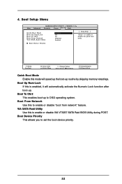
... to enable or disable VIA VT8237 SATA Raid BIOS Utility during POST. VIA SATA Raid Utility Use this is enabled, it will speed up the boot-up routine by skipping memory retestings. Boot Setup Menu Main Advanced AMIBIOS SETUP UTILITY - Boot Device Priority F1:Help Esc:Exit :Select Item :Select Menu +/-:Change Values Enter:Select Sub-Menu F9:Setup Defaults F10:Save & Exit Quick Boot Mode Enable this to enable or disable the quick boot mode. Boot Device Priority This allows you to OS/2 operating system. Boot From Network Use this mode...
... to enable or disable VIA VT8237 SATA Raid BIOS Utility during POST. VIA SATA Raid Utility Use this is enabled, it will speed up the boot-up routine by skipping memory retestings. Boot Setup Menu Main Advanced AMIBIOS SETUP UTILITY - Boot Device Priority F1:Help Esc:Exit :Select Item :Select Menu +/-:Change Values Enter:Select Sub-Menu F9:Setup Defaults F10:Save & Exit Quick Boot Mode Enable this to enable or disable the quick boot mode. Boot Device Priority This allows you to OS/2 operating system. Boot From Network Use this mode...


