User Manual
Page 3
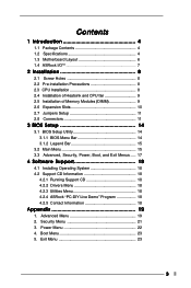
...21 3. Contents 1 Introduction 4 1.1 Package Contents 4 1.2 Specifications 4 1.3 Motherboard Layout 6 1.4 ASRock I/O 7 TM ...2 Installation 8 2.1 Screw Holes 8 2.2 Pre-installation Precautions 8 2.3 CPU Installation 8 2.4 Installation of Heatsink and CPU fan 9 2.5 Installation of Memory Modules (DIMM 9 2.6 Expansion Slots 10 2.7 Jumpers Setup 11 2.8 Connectors 11 3 BIOS Setup 14...CD Information 18 4.2.1 Running Support CD 18 4.2.2 Drivers Menu 18 4.2.3 Utilities Menu 18 4.2.4 ASRock "PC-DIY Live Demo" Program 18 4.2.5 Contact Information 18 Appendix 19 1. Exit Menu 23 3
...21 3. Contents 1 Introduction 4 1.1 Package Contents 4 1.2 Specifications 4 1.3 Motherboard Layout 6 1.4 ASRock I/O 7 TM ...2 Installation 8 2.1 Screw Holes 8 2.2 Pre-installation Precautions 8 2.3 CPU Installation 8 2.4 Installation of Heatsink and CPU fan 9 2.5 Installation of Memory Modules (DIMM 9 2.6 Expansion Slots 10 2.7 Jumpers Setup 11 2.8 Connectors 11 3 BIOS Setup 14...CD Information 18 4.2.1 Running Support CD 18 4.2.2 Drivers Menu 18 4.2.3 Utilities Menu 18 4.2.4 ASRock "PC-DIY Live Demo" Program 18 4.2.5 Contact Information 18 Appendix 19 1. Exit Menu 23 3
User Manual
Page 4
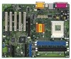
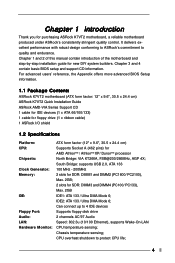
...ASRock K7VT2 motherboard (ATX form factor: 12" x 9.6", 30.5 x 24.4 cm) ASRock K7VT2 Quick Installation Guide ASRock AMD-VIA Series Support CD 1 cable for IDE devices (1 x ATA 66/100/133) 1 cable for floppy drive (1 x ribbon cable) 1 ASRock I/O shield 1.2 Specifications Platform: CPU: Chipsets: Clock Generator: Memory... 2 slots for DDR: DIMM1 and DIMM2 (PC1600/ PC2100), Max. 2GB; 2 slots for purchasing ASRock K7VT2 motherboard, a reliable motherboard produced under ASRock's consistently stringent quality control. Chapter 1 Introduction Thank you for SDR: DIMM3 and DIMM4 (PC100/ PC133...
...ASRock K7VT2 motherboard (ATX form factor: 12" x 9.6", 30.5 x 24.4 cm) ASRock K7VT2 Quick Installation Guide ASRock AMD-VIA Series Support CD 1 cable for IDE devices (1 x ATA 66/100/133) 1 cable for floppy drive (1 x ribbon cable) 1 ASRock I/O shield 1.2 Specifications Platform: CPU: Chipsets: Clock Generator: Memory... 2 slots for DDR: DIMM1 and DIMM2 (PC1600/ PC2100), Max. 2GB; 2 slots for purchasing ASRock K7VT2 motherboard, a reliable motherboard produced under ASRock's consistently stringent quality control. Chapter 1 Introduction Thank you for SDR: DIMM3 and DIMM4 (PC100/ PC133...
User Manual
Page 9
... and higher require larger heatsink and cooling fan. Also, for proper operation, it is in good contact with a speed of Memory Modules (DIMM) SDRAM (Synchronous DRAM) DIMM (Dual In-line Memory Module)has 168 pins and DDR (Double Data Rate) SDRAM DIMM has 184 pins. For proper installation, please kindly refer to...
... and higher require larger heatsink and cooling fan. Also, for proper operation, it is in good contact with a speed of Memory Modules (DIMM) SDRAM (Synchronous DRAM) DIMM (Dual In-line Memory Module)has 168 pins and DDR (Double Data Rate) SDRAM DIMM has 184 pins. For proper installation, please kindly refer to...
User Manual
Page 14
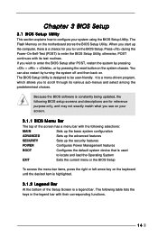
... your system using the BIOS Setup Utility. The following BIOS setup screens and descriptions are for you wish to run the BIOS Setup. The Flash Memory on . If you to enter the BIOS Setup after POST, restart the system by pressing + + , or by turning the system off and then back on...
... your system using the BIOS Setup Utility. The following BIOS setup screens and descriptions are for you wish to run the BIOS Setup. The Flash Memory on . If you to enter the BIOS Setup after POST, restart the system by pressing + + , or by turning the system off and then back on...
User Manual
Page 15
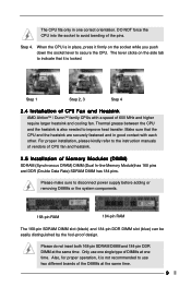
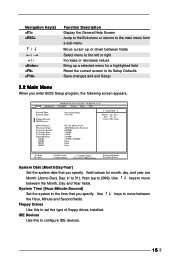
Dec Day: 01 - 31 Year: 1980 - 2099 K7VT2 BIOS P1.00 AMD Duron(tm) Processor 800MHz 128 KB 64 KB 128 MB 128 MB / 266MHz None None None F1:Help Esc:Exit :Select ... screen appears. Main Advanced System Date System Time Floppy Drives IDE Devices BIOS Version Processor Type Processor Speed L1 Cache Size L2 Cache Size Total Memory DDR1 DDR2 SDR1 SDR2 AMIBIOS SETUP UTILITY - Use keys to move between the Month, Day and Year fields. Navigation Key(s) / / + / Function Description Display the General...
Dec Day: 01 - 31 Year: 1980 - 2099 K7VT2 BIOS P1.00 AMD Duron(tm) Processor 800MHz 128 KB 64 KB 128 MB 128 MB / 266MHz None None None F1:Help Esc:Exit :Select ... screen appears. Main Advanced System Date System Time Floppy Drives IDE Devices BIOS Version Processor Type Processor Speed L1 Cache Size L2 Cache Size Total Memory DDR1 DDR2 SDR1 SDR2 AMIBIOS SETUP UTILITY - Use keys to move between the Month, Day and Year fields. Navigation Key(s) / / + / Function Description Display the General...
User Manual
Page 19
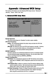
Advanced BIOS Setup Menu Spread Spectrum: This field should always be "Disabled" for graphics memory. However, this is selected, the motherboard detects the memory module(s) inserted and automatically assigns appropriate frequency. Wrong setup may cause problems during operation. PCI Delay Transaction: ...motherboard detects the jumper setup and sets the CPU host frequency automatically. [Manual]: This allows the user to a section of the PCI memory address range used for better system stability. Appendix: Advanced BIOS Setup This section will free the PCI Bus when the CPU is accessing...
Advanced BIOS Setup Menu Spread Spectrum: This field should always be "Disabled" for graphics memory. However, this is selected, the motherboard detects the memory module(s) inserted and automatically assigns appropriate frequency. Wrong setup may cause problems during operation. PCI Delay Transaction: ...motherboard detects the jumper setup and sets the CPU host frequency automatically. [Manual]: This allows the user to a section of the PCI memory address range used for better system stability. Appendix: Advanced BIOS Setup This section will free the PCI Bus when the CPU is accessing...
User Manual
Page 23
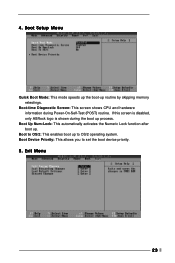
Boot Setup Menu Quick Boot Mode: This mode speeds up the boot-up process. If this screen is disabled, only ASRock logo is shown during Power-On-Self-Test (POST) routine. 4. Boot to OS/2: This enables boot up . Boot Up Num-Lock: This automatically activates the Numeric Lock function after boot up to set the boot device priority. 5. Exit Menu 23 Boot-time Diagnostic Screen: This screen shows CPU and hardware information during the boot up routine by skipping memory retestings. Boot Device Priority: This allows you to OS/2 operating system.
Boot Setup Menu Quick Boot Mode: This mode speeds up the boot-up process. If this screen is disabled, only ASRock logo is shown during Power-On-Self-Test (POST) routine. 4. Boot to OS/2: This enables boot up . Boot Up Num-Lock: This automatically activates the Numeric Lock function after boot up to set the boot device priority. 5. Exit Menu 23 Boot-time Diagnostic Screen: This screen shows CPU and hardware information during the boot up routine by skipping memory retestings. Boot Device Priority: This allows you to OS/2 operating system.

